Page 1394 of 1500

AUTO-CRUISE CONTROL
ENGINE AND EMISSION CONTROL17-63
CIRCUIT OPERATION
The Engine ECU detects "CRUISE" (MAIN) switch
"ON" signal to illuminate the "CRUISE" indicator
lamp on the combination meter.
.
COMMENT
Connector(s), wiring harness in the CAN bus line
between the Engine ECU and the combination
meter, power supply to the Engine ECU, the combi-
nation meter, the Engine ECU may be defective.
.
TROUBLESHOOTING HINTS
Malfunction of the combination meter.
Damaged harness or connector.
Malfunction of the Engine ECU.
Circuit drawings
Refer to circuit diagrams GROUP-90
Refer to configuration diagrams GROUP-80
Refer to component locations GROUP-70
DIAGNOSIS
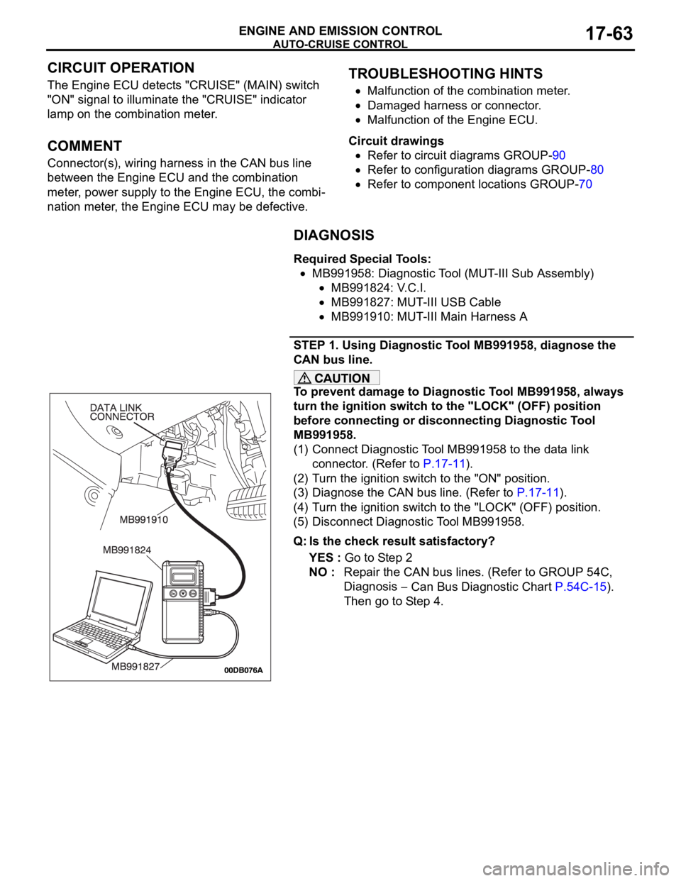
Required Special Tools:
MB991958: Diagnostic Tool (MUT-III Sub Assembly)
MB991824: V.C.I.
MB991827: MUT-III USB Cable
MB991910: MUT-III Main Harness A
STEP 1. Using Diagnostic Tool MB991958, diagnose the
CAN bus line.
To prevent damage to Diagnostic Tool MB991958, always
turn the ignition switch to the "LOCK" (OFF) position
before connecting or disconnecting Diagnostic Tool
MB991958.
(1) Connect Diagnostic Tool MB991958 to the data link
connector. (Refer to P.17-11).
(2) Turn the ignition switch to the "ON" position.
(3) Diagnose the CAN bus line. (Refer to P.17-11).
(4) Turn the ignition switch to the "LOCK" (OFF) position.
(5) Disconnect Diagnostic Tool MB991958.
Q: Is the check result satisfactory?
YES : Go to Step 2
NO : Repair the CAN bus lines. (Refer to GROUP 54C,
Diagnosis
Can Bus Diagnostic Chart P.54C-15).
Then go to Step 4.
Page 1400 of 1500
AUTO-CRUISE CONTROL
ENGINE AND EMISSION CONTROL17-69
SPECIAL TOOLSM1172000600509
TOOL TOOL NUMBER AND
NAMESUPERSESSION APPLICATION
MB991958
A: MB991824
B: MB991827
C: MB991910
D: MB991911
E: MB991914
F: MB991825
G: MB991826
MUT-III sub assembly
A: Vehicle
communication
interface (V.C.I.)
B: MUT-III USB cable
C: MUT-III main harness
A (Vehicles with CAN
communication
system)
D: MUT-III main harness
B (Vehicles without
CAN communication
system)
E: MUT-III main harness
C (for Daimler Chrysler
models only)
F: MUT-III measurement
adapter
G: MUT-III trigger
harnessMB991824-KIT
NOTE: G: MB991826
MUT-III trigger harness is
not necessary when
pushing V.C.I. ENTER
key.Checking diagnostic
trouble codes
For vehicles with CAN
communication, use
MUT-III main harness A
to send simulated
vehicle speed. If you
connect MUT-III main
harness B or C instead,
the CAN
communication does
not function correctly.
Page 1473 of 1500

AUTOMATIC TRANSMISSION DIAGNOSIS
AUTOMATIC TRANSMISSION23A-14
NOTE: If a sensor is disconnected when the ignition
switch is in the "ON" position, a diagnostic trouble
code is stored in memory. In this case, erase the
DTC using diagnostic tool.The diagnostic items are displayed in numeric order.
HOW TO CONNECT THE DIAGNOSTIC TOOL
(MUT-III)
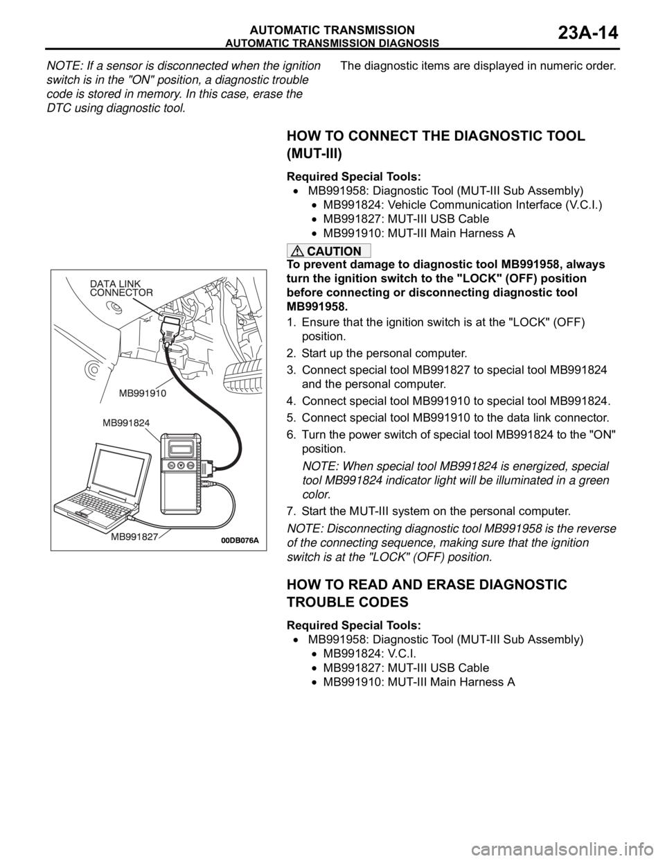
Required Special Tools:
MB991958: Diagnostic Tool (MUT-III Sub Assembly)
MB991824: Vehicle Communication Interface (V.C.I.)
MB991827: MUT-III USB Cable
MB991910: MUT-III Main Harness A
To prevent damage to diagnostic tool MB991958, always
turn the ignition switch to the "LOCK" (OFF) position
before connecting or disconnecting diagnostic tool
MB991958.
1. Ensure that the ignition switch is at the "LOCK" (OFF)
position.
2. Start up the personal computer.
3. Connect special tool MB991827 to special tool MB991824
and the personal computer.
4. Connect special tool MB991910 to special tool MB991824.
5. Connect special tool MB991910 to the data link connector.
6. Turn the power switch of special tool MB991824 to the "ON"
position.
NOTE: When special tool MB991824 is energized, special
tool MB991824 indicator light will be illuminated in a green
color.
7. Start the MUT-III system on the personal computer.
NOTE: Disconnecting diagnostic tool MB991958 is the reverse
of the connecting sequence, making sure that the ignition
switch is at the "LOCK" (OFF) position.
HOW TO READ AND ERASE DIAGNOSTIC
TROUBLE CODES
Required Special Tools:
MB991958: Diagnostic Tool (MUT-III Sub Assembly)
MB991824: V.C.I.
MB991827: MUT-III USB Cable
MB991910: MUT-III Main Harness A
Page 1474 of 1500

AUTOMATIC TRANSMISSION DIAGNOSIS
AUTOMATIC TRANSMISSION23A-15
To prevent damage to diagnostic tool MB991958, always
turn the ignition switch to the "LOCK" (OFF) position
before connecting or disconnecting diagnostic tool
MB991958.
NOTE: If the battery voltage is low, diagnostic trouble codes
will not be set. Check the battery if diagnostic tool
MB991958 does not display.
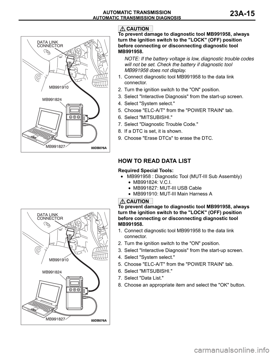
1. Connect diagnostic tool MB991958 to the data link
connector.
2. Turn the ignition switch to the "ON" position.
3. Select "Interactive Diagnosis" from the start-up screen.
4. Select "System select."
5. Choose "ELC-A/T" from the "POWER TRAIN" tab.
6. Select "MITSUBISHI."
7. Select "Diagnostic Trouble Code."
8. If a DTC is set, it is shown.
9. Choose "Erase DTCs" to erase the DTC.
HOW TO READ DATA LIST
Required Special Tools:
MB991958 : Diagnostic Tool (MUT-III Sub Assembly)
MB991824: V.C.I.
MB991827: MUT-III USB Cable
MB991910: MUT-III Main Harness A
To prevent damage to diagnostic tool MB991958, always
turn the ignition switch to the "LOCK" (OFF) position
before connecting or disconnecting diagnostic tool
MB991958.
1. Connect diagnostic tool MB991958 to the data link
connector.
2. Turn the ignition switch to the "ON" position.
3. Select "Interactive Diagnosis" from the start-up screen.
4. Select "System select."
5. Choose "ELC-A/T" from the "POWER TRAIN" tab.
6. Select "MITSUBISHI."
7. Select "Data List."
8. Choose an appropriate item and select the "OK" button.
Page 1475 of 1500
AUTOMATIC TRANSMISSION DIAGNOSIS
AUTOMATIC TRANSMISSION23A-16
HOW TO PERFORM ACTUATOR TEST
Required Special Tools:
MB991958: Diagnostic Tool (MUT-III Sub Assembly)
MB991824: V.C.I.
MB991827: MUT-III USB Cable
MB991910: MUT-III Main Harness A
To prevent damage to diagnostic tool MB991958, always
turn the ignition switch to the "LOCK" (OFF) position
before connecting or disconnecting diagnostic tool
MB991958.
1. Connect diagnostic tool MB991958 to the data link
connector.
2. Turn the ignition switch to the "ON" position.
3. Select "Interactive Diagnosis" from the start-up screen.
4. Select "System select."
5. Choose "ELC-A/T" from the "POWER TRAIN" tab.
6. Select "MITSUBISHI."
7. Select "Actuator Test."
8. Choose an appropriate item and select the "OK" button.
HOW TO DIAGNOSE THE CAN BUS LINES
Required Special Tools:
MB991958: Diagnostic Tool (MUT-III Sub Assembly)
MB991824: V.C.I.
MB991827: MUT-III USB Cable
MB991910: MUT-III Main Harness A
Page 1495 of 1500

AUTOMATIC TRANSMISSION DIAGNOSIS
AUTOMATIC TRANSMISSION23A-36
DIAGNOSTIC TROUBLE CODE PROCEDURES
(P0713): Transmission Fluid Temperature Sensor System (Open Circuit)
.
CIRCUIT OPERATION
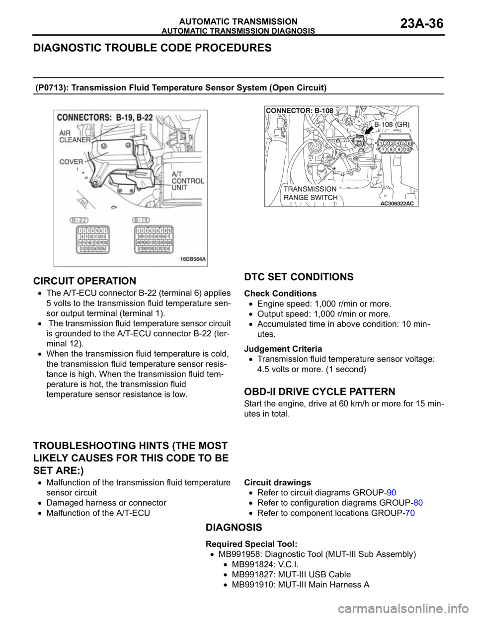
The A/T-ECU connector B-22 (terminal 6) applies
5 volts to the transmission fluid temperature sen-
sor output terminal (terminal 1).
The transmission fluid temperature sensor circuit
is grounded to the A/T-ECU connector B-22 (ter-
minal 12).
When the transmission fluid temperature is cold,
the transmission fluid temperature sensor resis-
tance is high. When the transmission fluid tem-
perature is hot, the transmission fluid
temperature sensor resistance is low.
.
DTC SET CONDITIONS
Check Conditions
Engine speed: 1,000 r/min or more.
Output speed: 1,000 r/min or more.
Accumulated time in above condition: 10 min-
utes.
Judgement Criteria
Transmission fluid temperature sensor voltage:
4.5 volts or more. (1 second)
.
OBD-II DRIVE CYCLE PATTERN
Start the engine, drive at 60 km/h or more for 15 min-
utes in total.
.
TROUBLESHOOTING HINTS (THE MOST
LIKELY CAUSES FOR THIS CODE TO BE
SET ARE:)
Malfunction of the transmission fluid temperature
sensor circuit
Damaged harness or connector
Malfunction of the A/T-ECUCircuit drawings
Refer to circuit diagrams GROUP-90
Refer to configuration diagrams GROUP-80
Refer to component locations GROUP-70
DIAGNOSIS
Required Special Tool:
MB991958: Diagnostic Tool (MUT-III Sub Assembly)
MB991824: V.C.I.
MB991827: MUT-III USB Cable
MB991910: MUT-III Main Harness A