2005 MITSUBISHI 380 USB
[x] Cancel search: USBPage 1343 of 1500
AUTO-CRUISE CONTROL
ENGINE AND EMISSION CONTROL17-12
To prevent damage to Diagnostic Tool MB991958, always
turn the ignition switch to the "LOCK" (OFF) position
before connecting or disconnecting Diagnostic Tool
MB991958.
1. Ensure that the ignition switch is at the "LOCK" (OFF)
position.
2. Start up the personal computer.
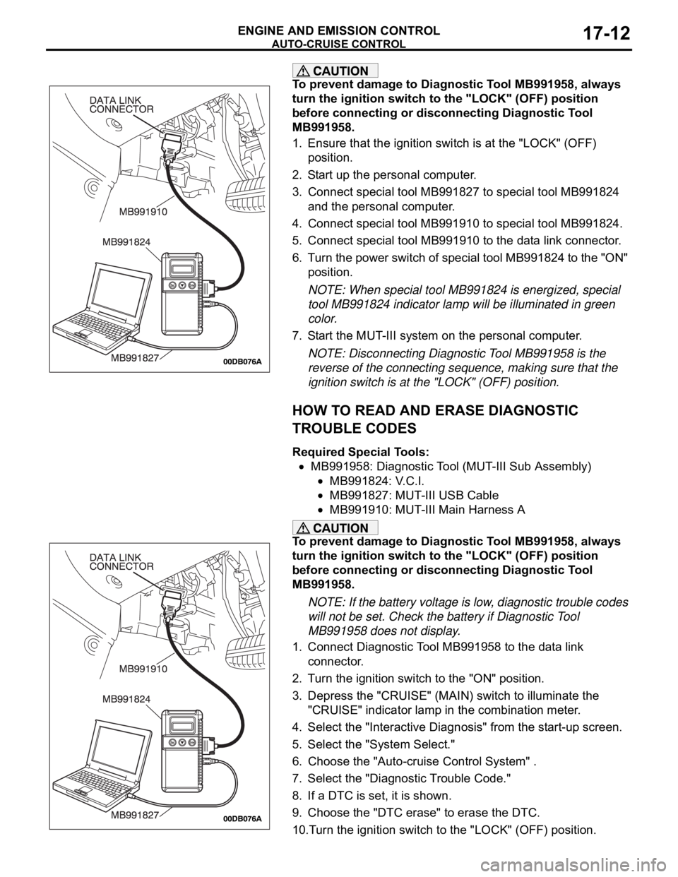
3. Connect special tool MB991827 to special tool MB991824
and the personal computer.
4. Connect special tool MB991910 to special tool MB991824.
5. Connect special tool MB991910 to the data link connector.
6. Turn the power switch of special tool MB991824 to the "ON"
position.
NOTE: When special tool MB991824 is energized, special
tool MB991824 indicator lamp will be illuminated in green
color.
7. Start the MUT-III system on the personal computer.
NOTE: Disconnecting Diagnostic Tool MB991958 is the
reverse of the connecting sequence, making sure that the
ignition switch is at the "LOCK" (OFF) position.
HOW TO READ AND ERASE DIAGNOSTIC
TROUBLE CODES
Required Special Tools:
MB991958: Diagnostic Tool (MUT-III Sub Assembly)
MB991824: V.C.I.
MB991827: MUT-III USB Cable
MB991910: MUT-III Main Harness A
To prevent damage to Diagnostic Tool MB991958, always
turn the ignition switch to the "LOCK" (OFF) position
before connecting or disconnecting Diagnostic Tool
MB991958.
NOTE: If the battery voltage is low, diagnostic trouble codes
will not be set. Check the battery if Diagnostic Tool
MB991958 does not display.
1. Connect Diagnostic Tool MB991958 to the data link
connector.
2. Turn the ignition switch to the "ON" position.
3. Depress the "CRUISE" (MAIN) switch to illuminate the
"CRUISE" indicator lamp in the combination meter.
4. Select the "Interactive Diagnosis" from the start-up screen.
5. Select the "System Select."
6. Choose the "Auto-cruise Control System" .
7. Select the "Diagnostic Trouble Code."
8. If a DTC is set, it is shown.
9. Choose the "DTC erase" to erase the DTC.
10.Turn the ignition switch to the "LOCK" (OFF) position.
Page 1344 of 1500
AUTO-CRUISE CONTROL
ENGINE AND EMISSION CONTROL17-13
11.Disconnect Diagnostic Tool MB991958.
HOW TO READ DATA LIST
Required Special Tools:
MB991958: Diagnostic Tool (MUT-III Sub Assembly)
MB991824: V.C.I.
MB991827: MUT-III USB Cable
MB991910: MUT-III Main Harness A
To prevent damage to Diagnostic Tool MB991958, always
turn the ignition switch to the "LOCK" (OFF) position
before connecting or disconnecting Diagnostic Tool
MB991958.
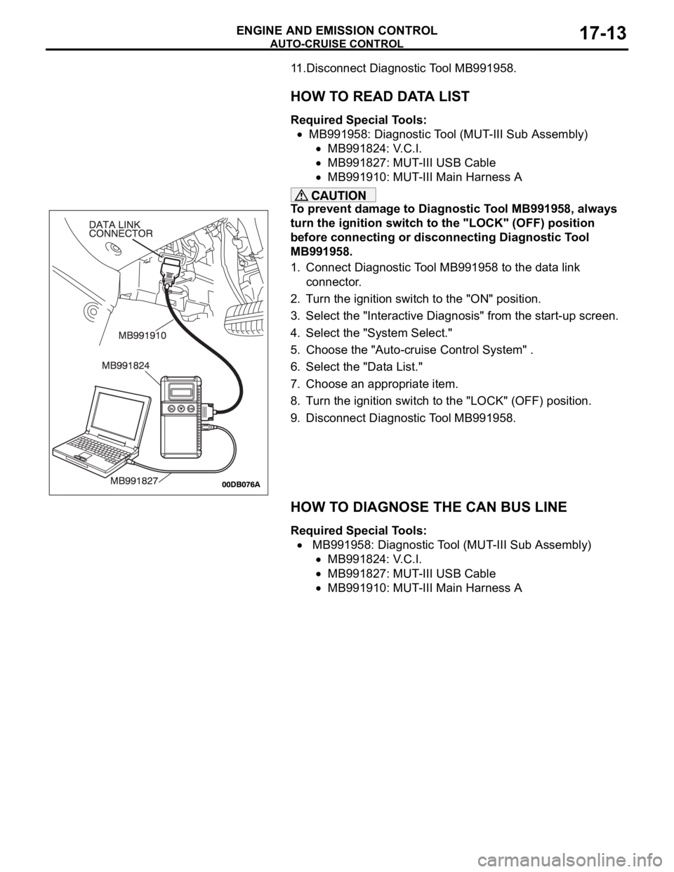
1. Connect Diagnostic Tool MB991958 to the data link
connector.
2. Turn the ignition switch to the "ON" position.
3. Select the "Interactive Diagnosis" from the start-up screen.
4. Select the "System Select."
5. Choose the "Auto-cruise Control System" .
6. Select the "Data List."
7. Choose an appropriate item.
8. Turn the ignition switch to the "LOCK" (OFF) position.
9. Disconnect Diagnostic Tool MB991958.
HOW TO DIAGNOSE THE CAN BUS LINE
Required Special Tools:
MB991958: Diagnostic Tool (MUT-III Sub Assembly)
MB991824: V.C.I.
MB991827: MUT-III USB Cable
MB991910: MUT-III Main Harness A
Page 1346 of 1500
AUTO-CRUISE CONTROL
ENGINE AND EMISSION CONTROL17-15
DIAGNOSTIC TROUBLE CODE PROCEDURES
DTC P0830: Clutch Switch (5M/T Only)
.
CIRCUIT OPERATION
A 5 Volt power supply is applied to the clutch
switch output terminal (terminal No. 1) from the
ENGINE-ECU(terminal No. B-21 pin 41) when
the clutch pedal is applied the power supply is
switched to earth.
.
TECHNICAL DESCRIPTION
The ENGINE-ECU uses the clutch switch earth-
ing as a signal that clutch pedal has been
applied.
.
DTC SET CONDITIONS
Check Conditions
Vehicle speed is above 50 km/h.Judgement Criteria
Gear shift is above 5 times.
Clutch control is below 2 times.
No MIL.
No Limp home.
.
TROUBLESHOOTING HINTS (The most
likely causes for this code to be set are:)
Clutch switch failed
Harness damage in clutch switch circuit, or con-
nector damage.
Refer to component locations GROUP-70
Refer to configuration diagrams GROUP-80
Refer to circuit diagrams GROUP-90
DIAGNOSIS
Required Special Tools:
: Diagnostic tool (MUT-III Sub Assembly)
MB991824: V.C.I.
MB991827: USB Cable
MB991910: Main Harness A
Page 1352 of 1500

AUTO-CRUISE CONTROL
ENGINE AND EMISSION CONTROL17-21
CIRCUIT OPERATION
This circuit judges the signals of each switch
("COAST/SET", "ACC/RES" and "CANCEL") of the
auto-cruise control switch. The Engine ECU detects
the state of the auto-cruise control switch by sensing
the voltages shown below.
When all switches are OFF: 4.7 5.0 volts
When the "CRUISE" (MAIN) switch is "ON": 0
0.3 volt
When the "COAST/SET" switch is ON: 2.0 2.8
volts
When the "ACC/RES" switch is ON: 3.3 4.1
volts
When the "CANCEL" switch is ON: 0.8 1.5 volts
.
DTC SET CONDITIONS
Check Condition
The "CRUISE" indicator lamp illuminates.Judgement Criteria
If the auto-cruise control switch is operated, this
DTC will be set when the Engine ECU terminal
voltage is different from the standard value.
.
TROUBLESHOOTING HINTS (THE MOST
LIKELY CAUSES FOR THIS CASE:)
Malfunction of the auto-cruise control switch.
Malfunction of the clock spring.
Damaged harness or connector.
Malfunction of the Engine ECU.
Circuit drawings
Refer to circuit diagrams GROUP-90
Refer to configuration diagrams GROUP-80
Refer to component locations GROUP-70
DIAGNOSIS
Required Special Tools:
MB991958: Diagnostic Tool (MUT-III Sub Assembly)
MB991824: V.C.I.
MB991827: MUT-III USB Cable
MB991910: MUT-III Main Harness A
MB991223: Harness Set
MB992044: ENGINE-ECU Check Harness
Page 1367 of 1500
AUTO-CRUISE CONTROL
ENGINE AND EMISSION CONTROL17-36
DIAGNOSIS
Required Special Tools:
MB991958: Diagnostic ToolDiagnostic Tool (MUT-III Sub
Assembly)
MB991824: V.C.I.
MB991827: MUT-III USB Cable
MB991910: MUT-III Main Harness A
MB991223: Harness Set
MB992044: ENGINE-ECU Check Harness
STEP 1. Using Diagnostic Tool MB991958, check data list
item 74: Stoplamp Switch.
To prevent damage to Diagnostic Tool MB991958, always
turn the ignition switch to the "LOCK" (OFF) position
before connecting or disconnecting Diagnostic Tool
MB991958.
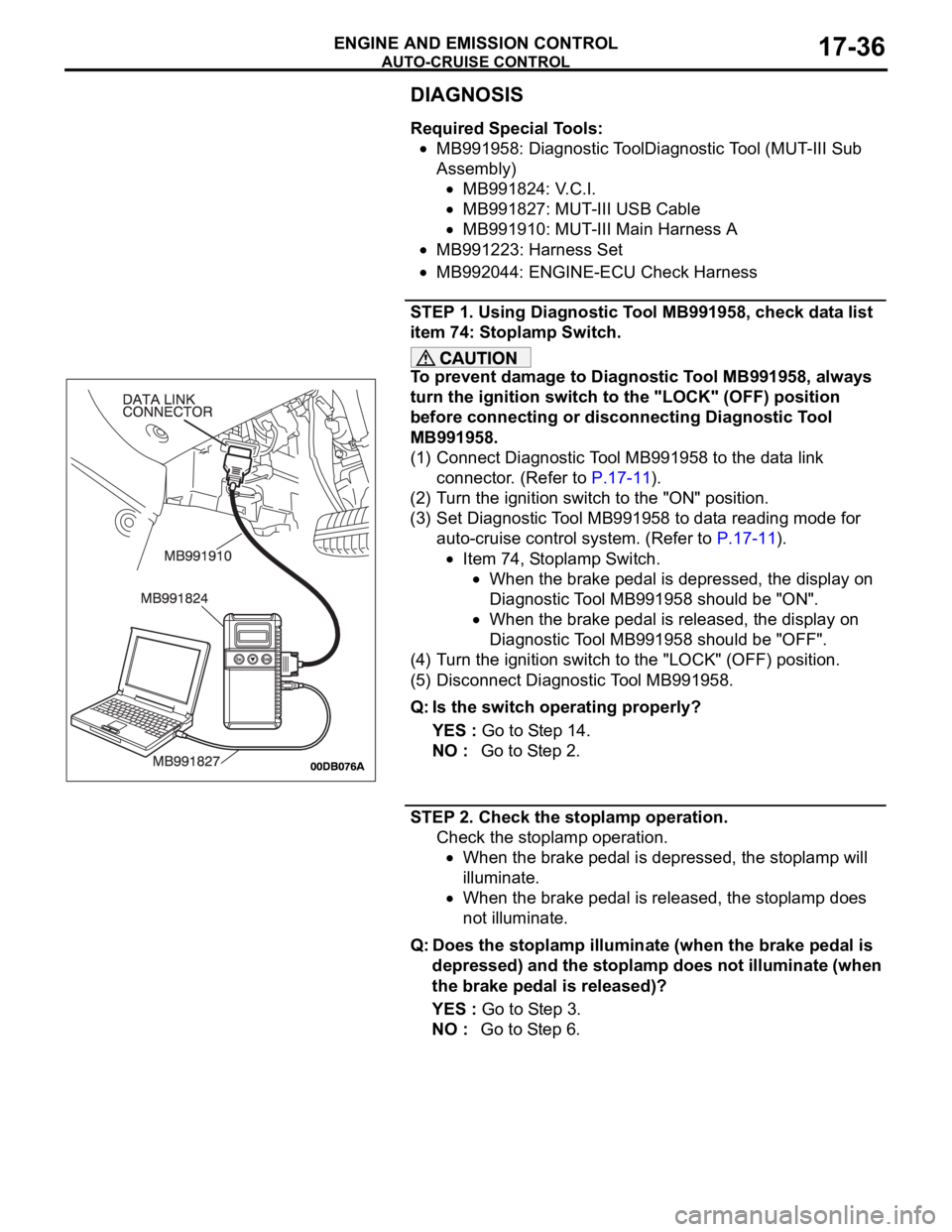
(1) Connect Diagnostic Tool MB991958 to the data link
connector. (Refer to P.17-11).
(2) Turn the ignition switch to the "ON" position.
(3) Set Diagnostic Tool MB991958 to data reading mode for
auto-cruise control system. (Refer to P.17-11).
Item 74, Stoplamp Switch.
When the brake pedal is depressed, the display on
Diagnostic Tool MB991958 should be "ON".
When the brake pedal is released, the display on
Diagnostic Tool MB991958 should be "OFF".
(4) Turn the ignition switch to the "LOCK" (OFF) position.
(5) Disconnect Diagnostic Tool MB991958.
Q: Is the switch operating properly?
YES : Go to Step 14.
NO : Go to Step 2.
STEP 2. Check the stoplamp operation.
Check the stoplamp operation.
When the brake pedal is depressed, the stoplamp will
illuminate.
When the brake pedal is released, the stoplamp does
not illuminate.
Q: Does the stoplamp illuminate (when the brake pedal is
depressed) and the stoplamp does not illuminate (when
the brake pedal is released)?
YES : Go to Step 3.
NO : Go to Step 6.
Page 1381 of 1500
AUTO-CRUISE CONTROL
ENGINE AND EMISSION CONTROL17-50
DTC 1574: Engine ECU and Its Related Components
.
DTC SET CONDITIONS
This DTC is set when there is a failure in the Engine
ECU and its related components.
.
TROUBLESHOOTING HINTS (THE MOST
LIKELY CAUSES FOR THIS CODE TO BE
SET ARE:)
Malfunction of the MPI system.
Malfunction of the A/T system.
Malfunction of the Engine ECU.
Circuit drawings
Refer to circuit diagrams GROUP-90
Refer to configuration diagrams GROUP-80
Refer to component locations GROUP-70
DIAGNOSIS
Required Special Tools:
MB991958: Diagnostic Tool (MUT-III Sub Assembly)
MB991824: V.C.I.
MB991827: MUT-III USB Cable
MB991910: MUT-III Main Harness A
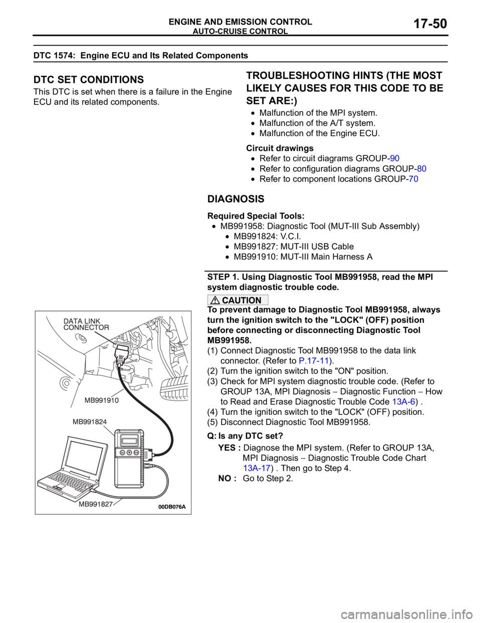
STEP 1. Using Diagnostic Tool MB991958, read the MPI
system diagnostic trouble code.
To prevent damage to Diagnostic Tool MB991958, always
turn the ignition switch to the "LOCK" (OFF) position
before connecting or disconnecting Diagnostic Tool
MB991958.
(1) Connect Diagnostic Tool MB991958 to the data link
connector. (Refer to P.17-11).
(2) Turn the ignition switch to the "ON" position.
(3) Check for MPI system diagnostic trouble code. (Refer to
GROUP 13A, MPI Diagnosis
Diagnostic Function How
to Read and Erase Diagnostic Trouble Code 13A-6) .
(4) Turn the ignition switch to the "LOCK" (OFF) position.
(5) Disconnect Diagnostic Tool MB991958.
Q: Is any DTC set?
YES : Diagnose the MPI system. (Refer to GROUP 13A,
MPI Diagnosis
Diagnostic Trouble Code Chart
13A-17) . Then go to Step 4.
NO : Go to Step 2.
Page 1387 of 1500
AUTO-CRUISE CONTROL
ENGINE AND EMISSION CONTROL17-56
INSPECTION PROCEDURE 5: Auto-cruise Control System cannot be Set.
.
COMMENT
The fail-safe function is probably canceling
auto-cruise control system. In this case, Diagnostic
Tool MB991958 can be used to retest each system
by checking the diagnostic trouble codes. The
Diagnostic Tool can also be used to check if the cir-
cuits of each input switch are normal or not by check-
ing the input switch codes.
.
TROUBLESHOOTING HINTS (THE MOST
LIKELY CAUSES FOR THIS CASE:)
Malfunction of the auto-cruise control switch.
Malfunction of the stoplamp switch.
Malfunction of the transmission inhibitor switch.
Malfunction of the Engine ECU.
Circuit drawings
Refer to circuit diagrams GROUP-90
Refer to configuration diagrams GROUP-80
Refer to component locations GROUP-70
DIAGNOSIS
Required Special Tools:
MB991958: Diagnostic Tool (MUT-III Sub Assembly)
MB991824: V.C.I.
MB991827: MUT-III USB Cable
MB991910: MUT-III Main Harness A
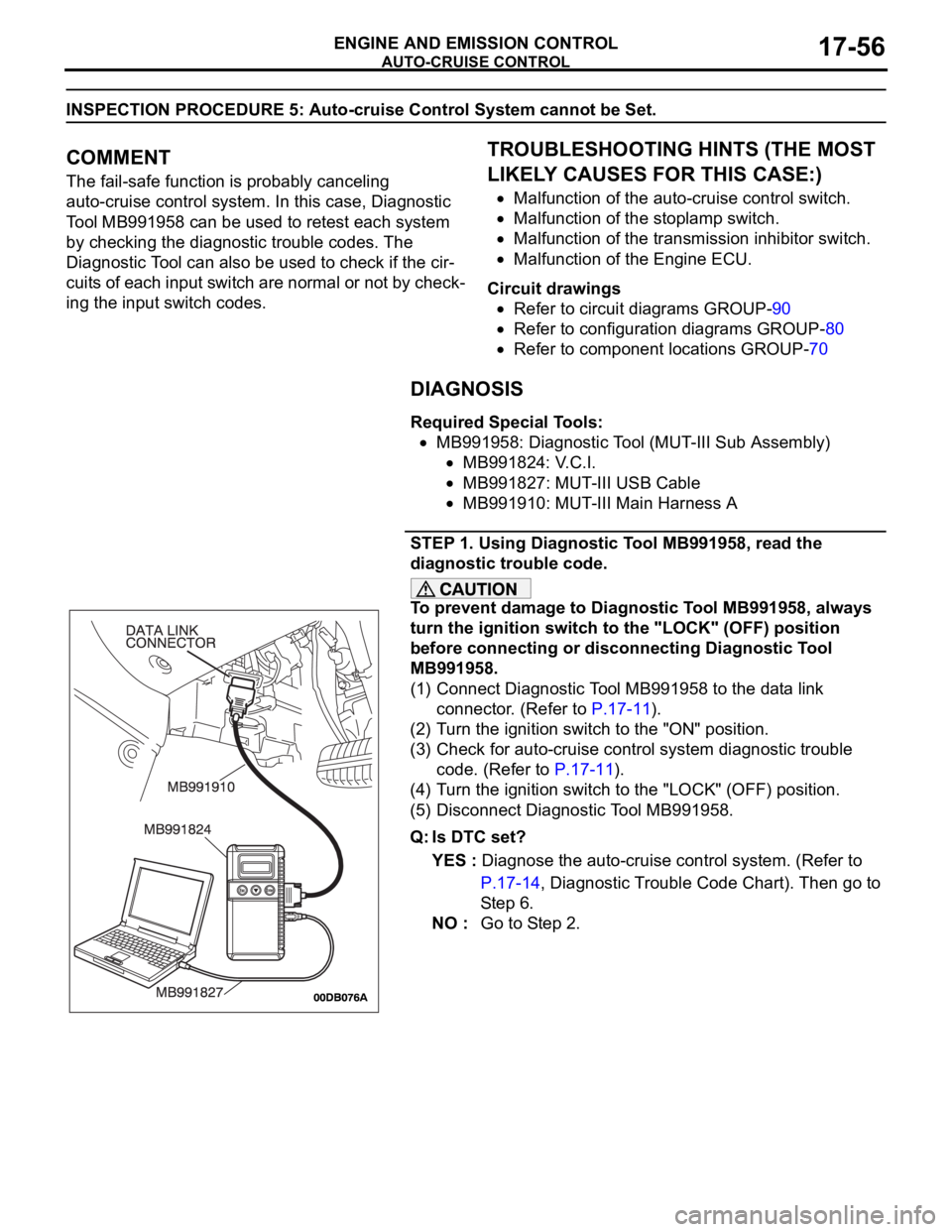
STEP 1. Using Diagnostic Tool MB991958, read the
diagnostic trouble code.
To prevent damage to Diagnostic Tool MB991958, always
turn the ignition switch to the "LOCK" (OFF) position
before connecting or disconnecting Diagnostic Tool
MB991958.
(1) Connect Diagnostic Tool MB991958 to the data link
connector. (Refer to P.17-11).
(2) Turn the ignition switch to the "ON" position.
(3) Check for auto-cruise control system diagnostic trouble
code. (Refer to P.17-11).
(4) Turn the ignition switch to the "LOCK" (OFF) position.
(5) Disconnect Diagnostic Tool MB991958.
Q: Is DTC set?
YES : Diagnose the auto-cruise control system. (Refer to
P.17-14, Diagnostic Trouble Code Chart). Then go to
St e p 6 .
NO : Go to Step 2.
Page 1391 of 1500
AUTO-CRUISE CONTROL
ENGINE AND EMISSION CONTROL17-60
INSPECTION PROCEDURE 6: Hunting (Repeated Acceleration and Deceleration) Occurs at the Set
Vehicle Speed.
.
COMMENT
The output shaft speed sensor signal or the throttle
body is suspected.
.
TROUBLESHOOTING HINTS (THE MOST
LIKELY CAUSES FOR THIS CASE:)
Malfunction of the output shaft speed sensor.
Malfunction of the throttle body.
Malfunction of the Engine ECU.
Malfunction of the A/T ECU.
Circuit drawings
Refer to circuit diagrams GROUP-90
Refer to configuration diagrams GROUP-80
Refer to component locations GROUP-70
DIAGNOSIS
Required Special Tools:
MB991958: Diagnostic Tool (MUT-III Sub Assembly)
MB991824: V.C.I.
MB991827: MUT-III USB Cable
MB991910: MUT-III Main Harness A
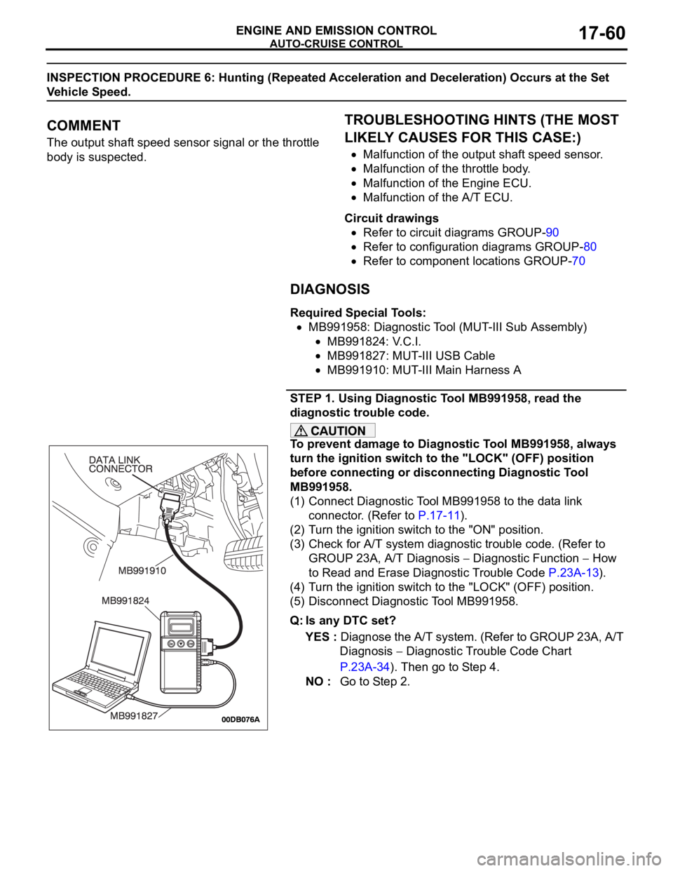
STEP 1. Using Diagnostic Tool MB991958, read the
diagnostic trouble code.
To prevent damage to Diagnostic Tool MB991958, always
turn the ignition switch to the "LOCK" (OFF) position
before connecting or disconnecting Diagnostic Tool
MB991958.
(1) Connect Diagnostic Tool MB991958 to the data link
connector. (Refer to P.17-11).
(2) Turn the ignition switch to the "ON" position.
(3) Check for A/T system diagnostic trouble code. (Refer to
GROUP 23A, A/T Diagnosis
Diagnostic Function How
to Read and Erase Diagnostic Trouble Code P.23A-13).
(4) Turn the ignition switch to the "LOCK" (OFF) position.
(5) Disconnect Diagnostic Tool MB991958.
Q: Is any DTC set?
YES : Diagnose the A/T system. (Refer to GROUP 23A, A/T
Diagnosis
Diagnostic Trouble Code Chart
P.23A-34). Then go to Step 4.
NO : Go to Step 2.