2005 MERCEDES-BENZ SPRINTER ECO mode
[x] Cancel search: ECO modePage 1157 of 1232
TEMPERATURE CONTROL
DESCRIPTION
The optional rear heater-A/C unit output tempera-
ture is controlled by a thumbwheel-type control,
mounted in the switch panel on the instrument
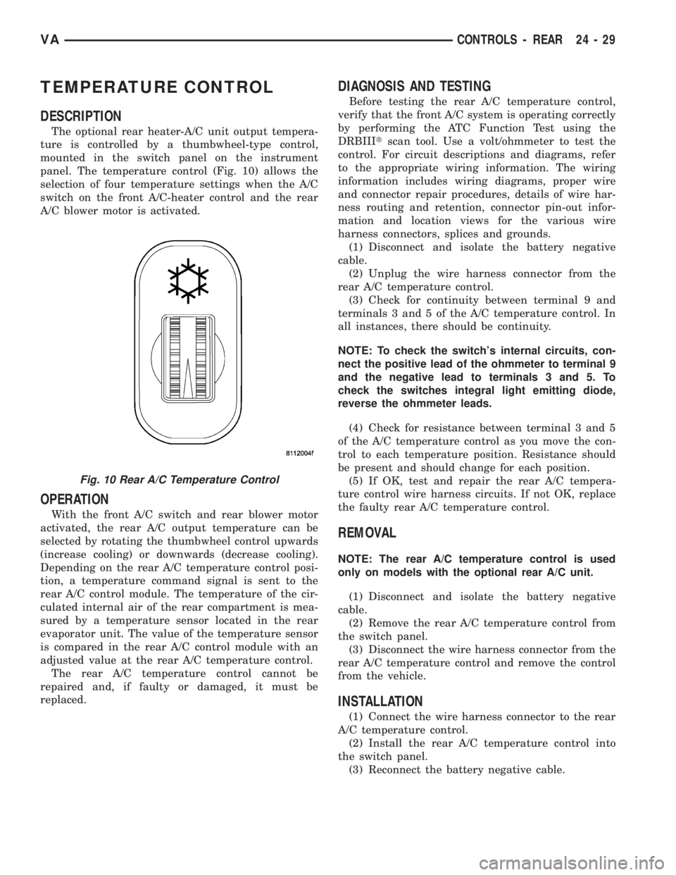
panel. The temperature control (Fig. 10) allows the
selection of four temperature settings when the A/C
switch on the front A/C-heater control and the rear
A/C blower motor is activated.
OPERATION
With the front A/C switch and rear blower motor
activated, the rear A/C output temperature can be
selected by rotating the thumbwheel control upwards
(increase cooling) or downwards (decrease cooling).
Depending on the rear A/C temperature control posi-
tion, a temperature command signal is sent to the
rear A/C control module. The temperature of the cir-
culated internal air of the rear compartment is mea-
sured by a temperature sensor located in the rear
evaporator unit. The value of the temperature sensor
is compared in the rear A/C control module with an
adjusted value at the rear A/C temperature control.
The rear A/C temperature control cannot be
repaired and, if faulty or damaged, it must be
replaced.
DIAGNOSIS AND TESTING
Before testing the rear A/C temperature control,
verify that the front A/C system is operating correctly
by performing the ATC Function Test using the
DRBIIItscan tool. Use a volt/ohmmeter to test the
control. For circuit descriptions and diagrams, refer
to the appropriate wiring information. The wiring
information includes wiring diagrams, proper wire
and connector repair procedures, details of wire har-
ness routing and retention, connector pin-out infor-
mation and location views for the various wire
harness connectors, splices and grounds.
(1) Disconnect and isolate the battery negative
cable.
(2) Unplug the wire harness connector from the
rear A/C temperature control.
(3) Check for continuity between terminal 9 and
terminals 3 and 5 of the A/C temperature control. In
all instances, there should be continuity.
NOTE: To check the switch's internal circuits, con-
nect the positive lead of the ohmmeter to terminal 9
and the negative lead to terminals 3 and 5. To
check the switches integral light emitting diode,
reverse the ohmmeter leads.
(4) Check for resistance between terminal 3 and 5
of the A/C temperature control as you move the con-
trol to each temperature position. Resistance should
be present and should change for each position.
(5) If OK, test and repair the rear A/C tempera-
ture control wire harness circuits. If not OK, replace
the faulty rear A/C temperature control.
REMOVAL
NOTE: The rear A/C temperature control is used
only on models with the optional rear A/C unit.
(1) Disconnect and isolate the battery negative
cable.
(2) Remove the rear A/C temperature control from
the switch panel.
(3) Disconnect the wire harness connector from the
rear A/C temperature control and remove the control
from the vehicle.
INSTALLATION
(1) Connect the wire harness connector to the rear
A/C temperature control.
(2) Install the rear A/C temperature control into
the switch panel.
(3) Reconnect the battery negative cable.
Fig. 10 Rear A/C Temperature Control
VACONTROLS - REAR 24 - 29
Page 1162 of 1232
(4) Remove floor distribution ducts from the center
floor distribution duct.
(5) Remove the shift mechanism (Refer to 21 -
TRANSMISSION/TRANSAXLE/AUTOMATIC -
NAG1/SHIFT MECHANISM - REMOVAL).
(6) Remove center floor distribution duct from the
heater housing.
INSTALLATION
(1) Install the center floor distribution duct onto
the heater housing.
(2) Install the shift mechanism (Refer to 21 -
TRANSMISSION/TRANSAXLE/AUTOMATIC -
NAG1/SHIFT MECHANISM - INSTALLATION).
(3) Install the left and right floor distribution
ducts onto the center floor distribution duct.
(4) Install the left and right floor distribution duct
retaining screws to the instrument panel support.
Tighten the screws to 2 N´m (17 in. lbs.).
(5) Install the defroster ducts (Refer to 24 - HEAT-
ING & AIR CONDITIONING/DISTRIBUTION/DE-
FROSTER DUCTS - INSTALLATION).
(6) Install the instrument panel (Refer to 23 -
BODY/INSTRUMENT PANEL/INSTRUMENT
PANEL ASSEMBLY - INSTALLATION).
HVAC HOUSING
REMOVAL
The heater housing assembly must be removed
from the vehicle and the two halves of the housing
separated for service access of the heater core, evap-
orator and each of the various mode doors.
WARNING: ON VEHICLES EQUIPPED WITH AIR-
BAGS, DISABLE THE AIRBAG SYSTEM BEFORE
ATTEMPTING ANY STEERING WHEEL, STEERING
COLUMN, OR INSTRUMENT PANEL COMPONENT
DIAGNOSIS OR SERVICE. DISCONNECT AND ISO-
LATE THE BATTERY NEGATIVE (GROUND) CABLE,
THEN WAIT TWO MINUTES FOR THE AIRBAG SYS-
TEM CAPACITOR TO DISCHARGE BEFORE PER-
FORMING FURTHER DIAGNOSIS OR SERVICE. THIS
IS THE ONLY SURE WAY TO DISABLE THE AIRBAG
SYSTEM. FAILURE TO TAKE THE PROPER PRE-
CAUTIONS COULD RESULT IN AN ACCIDENTAL
AIRBAG DEPLOYMENT AND POSSIBLE PERSONAL
INJURY.
WARNING: REVIEW THE WARNINGS AND CAU-
TIONS IN PLUMBING BEFORE PERFORMING THE
FOLLOWING OPERATION. (Refer to 24 - HEATING &
AIR CONDITIONING/PLUMBING - WARNING) (Refer
to 24 - HEATING & AIR CONDITIONING/PLUMBING -
CAUTION)
(1) Recover the refrigerant from the refrigerant
system. (Refer to 24 - HEATING & AIR CONDI-
TIONING/PLUMBING - STANDARD PROCEDURE -
REFRIGERANT RECOVERY)
(2) Partially drain the engine cooling system
(Refer to 7 - COOLING/ENGINE/COOLANT - STAN-
DARD PROCEDURE).
(3) Disconnect and isolate the battery negative
cable.
(4) Remove the air cleaner housing (Refer to 9 -
ENGINE/AIR INTAKE SYSTEM/AIR CLEANER
HOUSING - REMOVAL).
(5) Remove the windshield washer reservoir (Refer
to 8 - ELECTRICAL/WIPERS/WASHERS/WASHER
RESERVOIR - REMOVAL).
(6) Remove the air filter from the ventilation hous-
ing (Refer to 24 - HEATING & AIR CONDITION-
ING/DISTRIBUTION/AIR FILTER - REMOVAL).
(7) Disconnect the wire harness and vacuum con-
nectors from the recirculation door actuator (Refer to
24 - HEATING & AIR CONDITIONING/CONTROLS/
RECIRCULATION DOOR ACTUATOR - REMOVAL).
(8) Disconnect the wire harness connector from the
blower motor resistor block (Refer to 24 - HEATING
& AIR CONDITIONING/CONTROLS/BLOWER
MOTOR RESISTOR BLOCK - REMOVAL).
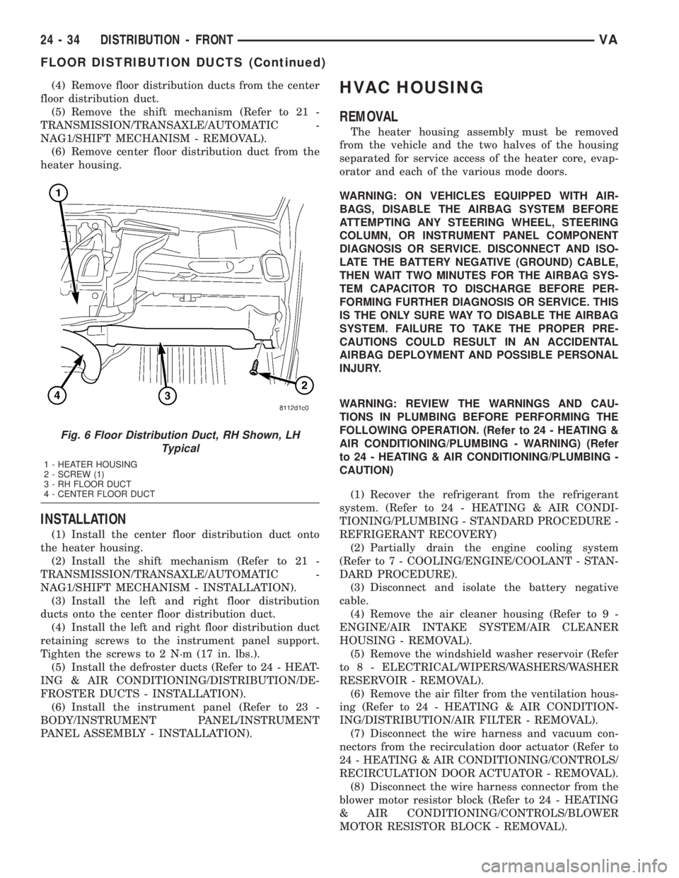
Fig. 6 Floor Distribution Duct, RH Shown, LH
Typical
1 - HEATER HOUSING
2 - SCREW (1)
3 - RH FLOOR DUCT
4 - CENTER FLOOR DUCT
24 - 34 DISTRIBUTION - FRONTVA
FLOOR DISTRIBUTION DUCTS (Continued)
Page 1165 of 1232
(4) Connect the heater-A/C control cables to the
mode door levers (Refer to 24 - HEATING & AIR
CONDITIONING/CONTROLS/MODE DOOR CABLE
- INSTALLATION).
(5) Reinstall the passenger airbag bracket (Refer
to 8 - ELECTRICAL/RESTRAINTS/PASSENGER
AIRBAG - INSTALLATION).
(6) Reconnect the two bulkhead ground connection
near the instrument cluster area.
(7) Reinstall the defroster, floor distribution and
instrument panel ducts.
(8) Reinstall the instrument panel (Refer to 23 -
BODY/INSTRUMENT PANEL/INSTRUMENT
PANEL ASSEMBLY - INSTALLATION).
(9) Unplug or remove the tape from the opened
refrigerant line fittings.
(10) Lubricate two new rubber o-ring seals with
clean refrigerant oil and install them onto the evap-
orator core fittings.
(11) Connect the refrigerant line terminal block to
the evaporator tubes.
(12) Install the two bolts that secure the refriger-
ant line terminal block to the evaporator. Tighten the
bolts to 5 N´m (45 in. lbs.).
(13) Unplug or remove the tape from the heater
core hoses and tubes.
(14) Connect the heater hoses to the heater core
tubes and install the heater hose clamps.
(15) Install the ventilation housing to the dash
panel.
(16) Install the nuts and washers that secure the
ventilation housing to the dash panel. Tighten the
nuts to 5 N´m (45 in. lbs.).
(17) Connect the wire harness connectors to the
blower motor, blower motor resistor block and the
recirculation door actuator.
(18) Connect the vacuum harness connector to the
recirculation door actuator.
(19) Install the air filter into the ventilation hous-
ing (Refer to 24 - HEATING & AIR CONDITION-
ING/DISTRIBUTION/AIR FILTER -
INSTALLATION).
(20) Install the windshield washer reservoir (Refer
to 8 - ELECTRICAL/WIPERS/WASHERS/WASHER
RESERVOIR - INSTALLATION).
(21) Install the air cleaner housing (Refer to 9 -
ENGINE/AIR INTAKE SYSTEM/AIR CLEANER
HOUSING - INSTALLATION).
(22) Reconnect the battery negative cable.
(23) Refill the engine cooling system (Refer to 7 -
COOLING/ENGINE/COOLANT - STANDARD PRO-
CEDURE).
(24) Evacuate the refrigerant system (Refer to 24 -
HEATING & AIR CONDITIONING/PLUMBING -
STANDARD PROCEDURE - REFRIGERANT SYS-
TEM EVACUATE).(25) Charge the refrigerant system (Refer to 24 -
HEATING & AIR CONDITIONING/PLUMBING -
STANDARD PROCEDURE - REFRIGERANT SYS-
TEM CHARGE).
(26) Start the engine and check for proper opera-
tion of the heating and air conditioning systems.
INSTRUMENT PANEL DUCTS
REMOVAL
(1) Remove the instrument panel (Refer to 23 -
BODY/INSTRUMENT PANEL/INSTRUMENT
PANEL ASSEMBLY - REMOVAL).
(2) Remove the defroster ducts (Refer to 24 -
HEATING & AIR CONDITIONING/DISTRIBUTION/
DEFROSTER DUCTS - REMOVAL).
(3) Remove the floor distribution ducts (Refer to 24
- HEATING & AIR CONDITIONING/DISTRIBU-
TION/FLOOR DISTRIBUTION DUCTS - REMOV-
AL).
(4) If removing the right instrument panel duct,
remove the passenger air bag module and bracket
(Refer to 8 - ELECTRICAL/RESTRAINTS/PASSEN-
GER AIRBAG - REMOVAL).
(5) Remove the screws that secure the left and/or
right instrument panel duct and remove the duct(s)
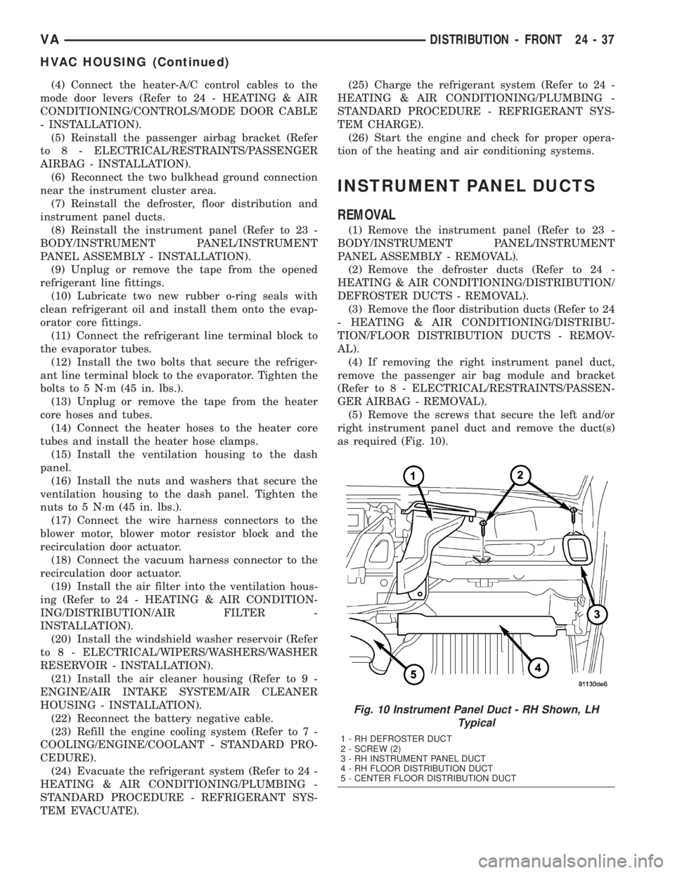
as required (Fig. 10).
Fig. 10 Instrument Panel Duct - RH Shown, LH
Typical
1 - RH DEFROSTER DUCT
2 - SCREW (2)
3 - RH INSTRUMENT PANEL DUCT
4 - RH FLOOR DISTRIBUTION DUCT
5 - CENTER FLOOR DISTRIBUTION DUCT
VADISTRIBUTION - FRONT 24 - 37
HVAC HOUSING (Continued)
Page 1174 of 1232
When it is necessary to open the refrigerant sys-
tem, have everything needed to service the system
ready. The refrigerant system should not be left open
to the atmosphere any longer than necessary. Cap or
plug all lines and fittings as soon as they are opened
to prevent the entrance of dirt and moisture. All lines
and components in parts stock should be capped or
sealed until they are to be installed.
All tools, including the refrigerant recycling equip-
ment, the manifold gauge set, and test hoses should
be kept clean and dry. All tools and equipment must
be designed for R-134a refrigerant.
DIAGNOSIS AND TESTING - REFRIGERANT
SYSTEM LEAKS
WARNING: REVIEW THE WARNINGS AND CAU-
TIONS IN THE FRONT OF THIS SECTION BEFORE
PERFORMING THE FOLLOWING OPERATION.
(Refer to 24 - HEATING & AIR CONDITIONING/
PLUMBING - WARNING) (Refer to 24 - HEATING &
AIR CONDITIONING/PLUMBING - CAUTION)
If the air conditioning system is not cooling prop-
erly, determine if the refrigerant system is fully-
charged. (Refer to 24 - HEATING & AIR
CONDITIONING - DIAGNOSIS AND TESTING -
A/C PERFORMANCE)
An electronic leak detector designed for R-134a
refrigerant is recommended for locating and confirm-
ing refrigerant system leaks. Refer to the operating
instructions supplied by the equipment manufacturer
for proper care and use of this equipment.
An oily residue on or near refrigerant system lines,
connector fittings, components, or component seals
can indicate the general location of a possible refrig-
erant leak. However, the exact leak location should
be confirmed with an electronic leak detector prior to
component repair or replacement.
To detect a leak in the refrigerant system, perform
one of the following procedures:
SYSTEM EMPTY
(1) Evacuate the refrigerant system. (Refer to 24 -
HEATING & AIR CONDITIONING/PLUMBING -
STANDARD PROCEDURE - REFRIGERANT SYS-
TEM EVACUATE)
(2) Connect and dispense 0.283 kilograms (0.625
pounds or 10 ounces) of R-134a refrigerant into the
evacuated refrigerant system. (Refer to 24 - HEAT-
ING & AIR CONDITIONING/PLUMBING - STAN-
DARD PROCEDURE - REFRIGERANT SYSTEM
CHARGE)
(3) Position the vehicle in a wind-free work area.
This will aid in detecting small leaks.(4) With the engine not running, use a electronic
R-134a leak detector and search for leaks. Because
R-134a refrigerant is heavier than air, the leak detec-
tor probe should be moved slowly along the bottom
side of all refrigerant lines, connector fittings and
components.
(5) To inspect the evaporator coil for leaks, insert
the electronic leak detector probe into the center
instrument panel outlet. Set the blower motor switch
to the lowest speed position, the A/C button in the
On position, and select the Recirculation Mode.
SYSTEM LOW
(1) Position the vehicle in a wind-free work area.
This will aid in detecting small leaks.
(2) Bring the refrigerant system up to operating
temperature and pressure. This is done by allowing
the engine to run with the air conditioning system
turned on for five minutes.
(3) With the engine not running, use a electronic
R-134a leak detector and search for leaks. Because
R-134a refrigerant is heavier than air, the leak detec-
tor probe should be moved slowly along the bottom
side of all refrigerant lines, connector fittings and
components.
(4) To inspect the evaporator coil for leaks, insert
the electronic leak detector probe into the center
instrument panel outlet. Set the blower motor switch
to the lowest speed position, the A/C button in the
On position, and select the Recirculation Mode.
STANDARD PROCEDURE
STANDARD PROCEDURE - REFRIGERANT
SYSTEM SERVICE EQUIPMENT
WARNING: EYE PROTECTION MUST BE WORN
WHEN SERVICING AN AIR CONDITIONING REFRIG-
ERANT SYSTEM. TURN OFF (ROTATE CLOCKWISE)
ALL VALVES ON THE EQUIPMENT BEING USED,
BEFORE CONNECTING TO OR DISCONNECTING
FROM THE REFRIGERANT SYSTEM. FAILURE TO
OBSERVE THESE WARNINGS MAY RESULT IN PER-
SONAL INJURY.
WARNING: REVIEW THE WARNINGS AND CAU-
TIONS IN THE FRONT OF THIS SECTION BEFORE
PERFORMING THE FOLLOWING OPERATION.
(Refer to 24 - HEATING & AIR CONDITIONING/
PLUMBING - WARNING) (Refer to 24 - HEATING &
AIR CONDITIONING/PLUMBING - CAUTION)
24 - 46 PLUMBINGVA
PLUMBING (Continued)
Page 1176 of 1232
(2) Open the low and high side valves and start
the charging station vacuum pump. When the suc-
tion gauge reads 88 kPa (26 in. Hg.) vacuum or
greater, close all of the valves and turn off the vac-
uum pump.
(a) If the refrigerant system fails to reach the
specified vacuum, the system has a leak that must
be corrected. (Refer to 24 - HEATING & AIR CON-
DITIONING/PLUMBING - DIAGNOSIS AND
TESTING - REFRIGERANT SYSTEM LEAKS)
(b) If the refrigerant system maintains the spec-
ified vacuum for five minutes, restart the vacuum
pump, open the suction and discharge valves and
evacuate the system for an additional ten minutes.
(3) Close all of the valves, and turn off the charg-
ing station vacuum pump.
(4) The refrigerant system is now ready to be
charged with R-134a refrigerant. (Refer to 24 -
HEATING & AIR CONDITIONING/PLUMBING -
STANDARD PROCEDURE - REFRIGERANT SYS-
TEM CHARGE)
STANDARD PROCEDURE - REFRIGERANT
SYSTEM CHARGE
WARNING: REVIEW THE WARNINGS AND CAU-
TIONS IN THE FRONT OF THIS SECTION BEFORE
PERFORMING THE FOLLOWING OPERATION.
(Refer to 24 - HEATING & AIR CONDITIONING/
PLUMBING - WARNING) (Refer to 24 - HEATING &
AIR CONDITIONING/PLUMBING - CAUTION)
CAUTION: A small amount of refrigerant oil is
removed from the A/C system each time the refrig-
erant system is recovered and evacuated. Before
charging the A/C system, you MUST replenish any
oil lost during the recovery process. Refer the
equipment manufacturer instructions for more infor-
mation.
After the refrigerant system has been tested for
leaks and evacuated, a refrigerant charge can be
injected into the system. (Refer to 24 - HEATING &
AIR CONDITIONING/PLUMBING - SPECIFICA-
TIONS - CHARGE CAPACITY)
A R-134a refrigerant recovery/recycling/charging
station that meets SAE Standard J2210 must be
used to charge the refrigerant system with R-134a
refrigerant. Refer to the operating instructions sup-
plied by the equipment manufacturer for proper care
and use of this equipment.
PARTIAL CHARGE METHOD
WARNING: REVIEW THE WARNINGS AND CAU-
TIONS IN THE FRONT OF THIS SECTION BEFORE
PERFORMING THE FOLLOWING OPERATION.
(Refer to 24 - HEATING & AIR CONDITIONING/
PLUMBING - WARNING) (Refer to 24 - HEATING &
AIR CONDITIONING/PLUMBING - CAUTION)
The partial charge method is used to add a partial
charge to a refrigerant system that is low on refrig-
erant. To perform this procedure the evaporator inlet
and outlet tube temperatures are measured. The
temperature difference is measured with a tempera-
ture meter with one or two clamp-on thermocouple
probes. The difference between the evaporator inlet
and outlet tube temperatures will determine the
amount of refrigerant needed.
Before adding a partial refrigerant charge, check
for refrigerant system leaks. (Refer to 24 - HEATING
& AIR CONDITIONING/PLUMBING - DIAGNOSIS
AND TESTING - REFRIGERANT SYSTEM LEAKS)
If a leak is found, make the necessary repairs before
attempting a full or partial refrigerant charge.
(1) Attach a manifold gauge set to the refrigerant
system service ports.
(2) Attach the two clamp-on thermocouple probes
to the inlet and outlet tubes of the evaporator coil.
²If a single thermocouple probe is used, attach
the probe to the evaporator inlet tube just before the
collar of the refrigerant line connector fitting. The
probe must make contact with the bottom surface of
the evaporator inlet tube.
²If dual thermocouple probes are used, attach
probe 1 to the evaporator inlet tube, and probe 2 to
the evaporator outlet tube. Attach both probes to the
evaporator tubes just before the collar of the refrig-
erant line connector fittings. The probes must make
contact with the bottom surfaces of the evaporator
inlet and outlet tubes.
(3) Open all of the windows or doors of the passen-
ger compartment.
(4) Set the A/C button on the A/C Heater controls
to the on position, the temperature control knob in
the full cool position, select Recirculation Mode, and
place the blower motor switch in the highest speed
position.
(5) Start the engine and hold the engine idle speed
at 1,000 rpm. Allow the engine to warm up to normal
operating temperature.
(6) The compressor clutch may cycle, depending
upon ambient temperature, humidity, and the refrig-
erant system charge level.
(7) Hold the engine idle speed at 1,000 rpm.
(8) Allow three to five minutes for the refrigerant
system to stabilize, then record the temperatures of
the evaporator inlet and outlet tubes.
24 - 48 PLUMBINGVA
PLUMBING (Continued)
Page 1177 of 1232
²If a single probe is used, record the temperature
of the evaporator inlet tube. Then remove the probe
from the inlet tube and attach it to the evaporator
outlet tube just before the collar of the refrigerant
line connector fitting. The probe must make contact
with the bottom surface of the evaporator outlet tube.
Allow the thermocouple and meter time to stabilize,
then record the temperature of the evaporator outlet
tube. Subtract the inlet tube temperature reading
from the outlet tube temperature reading.
²If dual probes are used, record the temperatures
of both the evaporator inlet and outlet tubes. Then
subtract the inlet tube temperature reading from the
outlet tube temperature reading.(9) If the measured temperature differential is
higher than 22É C to 26É C (40É F to 47É F), add 0.4
kilograms (14 ounces) of refrigerant.
(10) Allow three to five minutes for the refrigerant
system to stabilize, then take a second set of thermo-
couple measurements. Record the temperature differ-
ence to determine if an additional charge is required.
(11) Record the compressor discharge pressure. If
the reading is higher than the pressure shown in the
Compressor Discharge Pressure Chart, the system
could be overcharged. If the reading is equal to, or
lower, than the pressure shown in the chart, continue
with this procedure.
Compressor Discharge Pressure Chart
Ambient
Temperature16ÉC
(60ÉF)21ÉC
(70ÉF)27ÉC
(80ÉF)32ÉC
(90ÉF)38ÉC
(100ÉF)43ÉC
(110ÉF)
Compressor
Discharge
Pressure1378 kPa
(200 psi)1516 kPa
(220 psi)1723 kPa
(250psi)1930 kPa
(280 psi)2206 kPa
(320 psi)2413 kPa
(350 psi)
(12)EXAMPLE:The ambient temperature is 21É
C (70É F). The evaporator inlet tube temperature is
12É C (54É F) and the evaporator outlet tube temper-
ature is 10É C (50É F). Subtract the inlet tube tem-
perature from the outlet tube temperature. The
difference is -2É C (-4É F). With a -2É C (-4É F) tem-
perature differential at 21É C (70É F) ambient tem-
perature, the system is fully charged.
(13) Add enough refrigerant to bring the refriger-
ant system up to a full charge.
(14) Remove the jumper wire from the low pres-
sure cycling clutch switch wire harness connector
and plug the connector back into the switch.
SPECIFICATIONS
CHARGE CAPACITY
Always refer to the underhood HVAC Specification
Tag for the latest fill specification for the model being
serviced.
A/C COMPRESSOR
DESCRIPTION
The air conditioning system uses a Nippondenso
7SBU16C double-acting, variable swash plate-type
compressor on all models. This compressor has a
label identifying the use of R-134a refrigerant and
both the suction and discharge ports located on the
cylinder head.
OPERATION
The compressor is driven by the engine through an
electric clutch, drive pulley and belt arrangement.
The compressor is lubricated by refrigerant oil that is
circulated throughout the refrigerant system with the
refrigerant.
The compressor draws in low-pressure refrigerant
vapor from the evaporator through its suction port. It
then compresses the refrigerant into a high-pressure,
high-temperature refrigerant vapor, which is then
pumped to the condenser through the compressor dis-
charge port.
The compressor cannot be repaired. If faulty or
damaged, the entire compressor assembly must be
replaced. The compressor clutch, pulley, and coil, are
available for service.
DIAGNOSIS AND TESTING - COMPRESSOR
NOISE
When investigating an air conditioning related
noise, you must first know the conditions under
which the noise occurs. These conditions include:
weather, vehicle speed, transmission in gear or neu-
tral, engine speed, engine temperature, and any
other special conditions. Noises that develop during
air conditioning operation can often be misleading.
For example: What sounds like a failed front bearing
or connecting rod, may be caused by loose bolts, nuts,
mounting brackets, or a loose compressor clutch
assembly.
VAPLUMBING 24 - 49
PLUMBING (Continued)
Page 1215 of 1232
COVER - REMOVAL, TIMING CHAIN.......9-59
COVER - REMOVAL, TOP..............23-64
COVER - TRAY - INSTALLATION, TOP.....23-64
COVER - TRAY - REMOVAL, TOP........23-63
COVER(S) - INSTALLATION, CYLINDER
HEAD...............................9-30
COVER(S) - REMOVAL, CYLINDER HEAD . . . 9-30
COWL TRIM - INSTALLATION...........23-70
COWL TRIM - REMOVAL...............23-70
CRADLE CROSSMEMBER -
INSTALLATION, ENGINE................13-8
CRADLE CROSSMEMBER - REMOVAL,
ENGINE.............................13-6
CRANKSHAFT - INSTALLATION...........9-36
CRANKSHAFT - REMOVAL..............9-35
CRANKSHAFT AND BLOCK JOURNALS -
STANDARD PROCEDURE, MEASURE......9-35
CRANKSHAFT OIL SEAL - FRONT -
INSTALLATION........................9-38
CRANKSHAFT OIL SEAL - FRONT -
REMOVAL...........................9-38
CRANKSHAFT OIL SEAL - REAR -
INSTALLATION........................9-37
CRANKSHAFT OIL SEAL - REAR -
REMOVAL...........................9-37
CRANKSHAFT POSITION SENSOR -
DESCRIPTION.......................14-20
CRANKSHAFT POSITION SENSOR -
INSTALLATION.......................14-20
CRANKSHAFT POSITION SENSOR -
OPERATION..........................14-20
CRANKSHAFT POSITION SENSOR -
REMOVAL..........................14-20
CROSSMEMBER - INSTALLATION,
ENGINE CRADLE......................13-8
CROSSMEMBER - INSTALLATION,
RADIATOR..........................23-48
CROSSMEMBER - REMOVAL, ENGINE
CRADLE.............................13-6
CROSSMEMBER - REMOVAL, RADIATOR . . 23-47
CROSSMEMBER - TRANSMISSION -
INSTALLATION, REAR..................13-9
CROSSMEMBER - TRANSMISSION -
REMOVAL, REAR......................13-9
CUP HOLDER - INSTALLATION..........23-56
CUP HOLDER - REMOVAL..............23-55
CUSHION - FRONT - INSTALLATION,
SEAT ..............................23-78
CUSHION - FRONT - REMOVAL, SEAT....23-78
CUSHION/COVER - REAR -
INSTALLATION, SEAT.................23-80
CUSHION/COVER - REAR -
INSTALLATION, SEAT BACK............23-80
CUSHION/COVER - REAR - REMOVAL,
SEAT
..............................23-80
CUSHION/COVER - REAR - REMOVAL,
SEAT BACK
.........................23-80
CYLINDER - INSTALLATION, KEY/LOCK
....19-7
CYLINDER - INSTALLATION, LOCK
.......23-18
CYLINDER - INSTALLATION, MASTER
.....5-18
CYLINDER - REMOVAL, KEY/LOCK
........19-6
CYLINDER - REMOVAL, LOCK
...........23-18
CYLINDER - REMOVAL, MASTER
.........5-17
CYLINDER BLEEDING - STANDARD
PROCEDURE, MASTER
.................5-17
CYLINDER BORES - STANDARD
PROCEDURE, MEASURING
..............9-34
CYLINDER HEAD - INSTALLATION
........9-25
CYLINDER HEAD - REMOVAL
............9-22
CYLINDER HEAD BOLT INSPECTION -
STANDARD PROCEDURE
................9-21
CYLINDER HEAD COVER(S) -
INSTALLATION
........................9-30
CYLINDER HEAD COVER(S) - REMOVAL
. . . 9-30
CYLINDER HEAD FRONT COVER -
INSTALLATION
........................9-26
CYLINDER HEAD FRONT COVER -
REMOVAL
...........................9-23
CYLINDER HEAD GUIDE RAIL -
INSTALLATION
........................9-26
CYLINDER HEAD GUIDE RAIL -
REMOVAL
...........................9-24
CYLINDER HEAD SURFACE - STANDARD
PROCEDURE, MEASURE
................9-21
CYLINDER LEAK DOWN TEST -
STANDARD PROCEDURE
.................9-3CYLINDER PRESSURE LOSS -
STANDARD PROCEDURE,
DETERMINING.........................9-4
CYLINDER/POWER BOOSTER -
DIAGNOSIS AND TESTING, MASTER......5-16
DAMPER - INSTALLATION, VIBRATION.....9-48
DAMPER - REMOVAL, VIBRATION........9-47
DAYTIME RUNNING LAMP RELAY -
INSTALLATION........................8L-9
DAYTIME RUNNING LAMP RELAY -
REMOVAL...........................8L-9
DCHA - DIAGNOSIS AND TESTING,
DIESEL SUPPLEMENTAL HEATER........24-72
DECOUPLER - DIAGNOSIS AND
TESTING, GENERATOR................8F-19
DECOUPLER PULLEY - DESCRIPTION,
GENERATOR........................8F-19
DECOUPLER PULLEY - INSTALLATION,
GENERATOR........................8F-21
DECOUPLER PULLEY - OPERATION,
GENERATOR........................8F-19
DECOUPLER PULLEY - REMOVAL,
GENERATOR........................8F-20
DEFROSTER DUCTS - INSTALLATION.....24-33
DEFROSTER DUCTS - REMOVAL.........24-33
DELAY RELAY - INSTALLATION, TIME....8L-33
DELAY RELAY - REMOVAL, TIME........8L-32
DEPLOYMENT - STANDARD
PROCEDURE, SERVICE AFTER A
SUPPLEMENTAL RESTRAINT............8O-6
DETERMINING CYLINDER PRESSURE
LOSS - STANDARD PROCEDURE..........9-4
DEVICES - STANDARD PROCEDURE,
ELECTROSTATIC DISCHARGE (ESD)
SENSITIVE........................8W-01-7
DIAGRAMS - DESCRIPTION, HOW TO
USE WIRING......................8W-01-1
DIAGRAMS, DIAGNOSIS AND TESTING -
SCHEMATICS........................21-47
DIESEL - DESCRIPTION, 2.7L............11-1
DIESEL - SPECIFICATIONS, STARTER
MOTOR............................8F-29
DIESEL - TORQUE, 2.7L...............8F-17
DIESEL - TORQUE, STARTER...........8F-29
DIESEL ENGINE - DESCRIPTION, FUEL
REQUIREMENTS.......................0-1
DIESEL ENGINE - DIAGNOSIS AND
TESTING............................11-2
DIESEL ENGINES - DESCRIPTION,
ENGINE OIL...........................0-3
DIESEL SUPPLEMENTAL HEATER - DCHA
- DIAGNOSIS AND TESTING............24-72
DIMENSIONS - SPECIFICATIONS, FRAME . . . 13-4
DIMENSIONS - SPECIFICATIONS,
OPENING...........................23-90
DIODE - INSTALLATION.............8W-01-9
DIODE - REMOVAL.................8W-01-9
DISCHARGE (ESD) SENSITIVE DEVICES -
STANDARD PROCEDURE,
ELECTROSTATIC...................8W-01-7
DISCHARGE LINE - INSTALLATION, A/C . . . 24-54
DISCHARGE LINE - REMOVAL, A/C.......24-53
DISCONNECTING AND CONNECTING
FUEL LINES - STANDARD PROCEDURE....14-2
DISTRIBUTION - DESCRIPTION,
POWER..........................8W-97-1
DISTRIBUTION - OPERATION, POWER . . 8W-97-1
DISTRIBUTION CENTER - DESCRIPTION,
POWER..........................8W-97-3
DISTRIBUTION CENTER - OPERATION,
POWER..........................8W-97-3
DISTRIBUTION DUCTS - INSTALLATION,
FLOOR.............................24-34
DISTRIBUTION DUCTS - REMOVAL,
FLOOR.............................24-33
DOME LAMP/INTRUSION SENSOR -
INSTALLATION.......................8L-31
DOME LAMP/INTRUSION SENSOR -
REMOVAL..........................8L-31
DOME LAMP/INTRUSION SENSOR BULB
- INSTALLATION
.....................8L-30
DOME LAMP/INTRUSION SENSOR BULB
- REMOVAL
.........................8L-30
DOME/READING LAMP BULB -
INSTALLATION
.......................8L-29
DOME/READING LAMP BULB - REMOVAL
. 8L-29
DOME/READING LAMP UNIT -
INSTALLATION
.......................8L-30DOME/READING LAMP UNIT - REMOVAL . . 8L-30
DOOR - ASSEMBLY...................23-28
DOOR - ASSEMBLY, SLIDING...........23-43
DOOR - DISASSEMBLY................23-26
DOOR - DISASSEMBLY, SLIDING........23-42
DOOR - INSTALLATION...........23-14,23-30
DOOR - INSTALLATION, FUEL FILL.......23-47
DOOR - INSTALLATION, SLIDING........23-44
DOOR - REMOVAL...............23-14,23-25
DOOR - REMOVAL, FUEL FILL..........23-47
DOOR - REMOVAL, SLIDING............23-41
DOOR ACTUATOR - DESCRIPTION,
RECIRCULATION.....................24-20
DOOR ACTUATOR - INSTALLATION,
RECIRCULATION.....................24-21
DOOR ACTUATOR - OPERATION,
RECIRCULATION.....................24-20
DOOR ACTUATOR - REMOVAL,
RECIRCULATION.....................24-21
DOOR CABLES - INSTALLATION, MODE . . . 24-19
DOOR CABLES - REMOVAL, MODE.......24-19
DOOR GLASS - INSTALLATION....23-15,23-31,
23-46
DOOR GLASS - REMOVAL . . . 23-15,23-31,23-46
DOOR INNER BELT WEATHERSTRIP -
INSTALLATION, FRONT................23-87
DOOR INNER BELT WEATHERSTRIP -
REMOVAL, FRONT....................23-87
DOOR JAMB SWITCH - INSTALLATION.....8L-31
DOOR JAMB SWITCH - REMOVAL.......8L-31
DOOR LOCK MOTOR - INSTALLATION.....8N-1
DOOR LOCK MOTOR - REMOVAL.........8N-1
DOOR OPENING SEALS - INSTALLATION . . 23-87
DOOR OPENING SEALS - REMOVAL......23-87
DOOR OUTER BELT WEATHERSTRIP -
INSTALLATION, FRONT................23-87
DOOR OUTER BELT WEATHERSTRIP -
REMOVAL, FRONT....................23-87
DOSING PUMP - DESCRIPTION, FUEL....24-74
DOSING PUMP - INSTALLATION, FUEL....24-74
DOSING PUMP - OPERATION, FUEL......24-74
DOSING PUMP - REMOVAL, FUEL.......24-74
DOUBLE INVERTED FLARING -
STANDARD PROCEDURE.................5-8
D-PILLAR TRIM - INSTALLATION........23-70
D-PILLAR TRIM - REMOVAL............23-70
DRAIN AND FILL - STANDARD
PROCEDURE.........................3-11
DRAINING COOLING SYSTEM -
STANDARD PROCEDURE................7-12
DRAINING WATER FROM FUEL FILTER -
STANDARD PROCEDURES...............14-2
DRAW TEST - STANDARD PROCEDURE,
IGNITION-OFF.......................8F-10
DRIVE BELT - DIAGNOSIS AND TESTING,
ACCESSORY..........................7-5
DRIVE BELTS - INSTALLATION............7-8
DRIVE BELTS - REMOVAL................7-8
DRIVE VISCOUS CLUTCH -
INSTALLATION, FAN...................7-16
DRIVE VISCOUS CLUTCH - REMOVAL,
FAN ................................7-16
DRIVER AIRBAG - DESCRIPTION........8O-16
DRIVER AIRBAG - INSTALLATION.......8O-18
DRIVER AIRBAG - OPERATION..........8O-17
DRIVER AIRBAG - REMOVAL...........8O-17
DRIVER HEATED SEAT SWITCH -
DESCRIPTION........................8G-2
DRIVER HEATED SEAT SWITCH -
DIAGNOSIS AND TESTING..............8G-2
DRIVER HEATED SEAT SWITCH -
INSTALLATION.......................8G-3
DRIVER HEATED SEAT SWITCH -
OPERATION..........................8G-2
DRIVER HEATED SEAT SWITCH -
REMOVAL...........................8G-3
DRIVING CLUTCH K1 - ASSEMBLY.......21-75
DRIVING CLUTCH K1 - DISASSEMBLY....21-74
DRIVING CLUTCH K2 - ASSEMBLY.......21-78
DRIVING CLUTCH K2 - DISASSEMBLY....21-76
DRIVING CLUTCH K3 - ASSEMBLY.......21-80
DRIVING CLUTCH K3 - DISASSEMBLY
....21-80
DRIVING CLUTCHES - DESCRIPTION
.....21-72
DRIVING CLUTCHES - OPERATION
.......21-72
DROP - STANDARD PROCEDURE,
TESTING FOR A VOLTAGE
............8W-01-8
DRUM IN HAT BRAKE - CLEANING,
REAR
...............................5-27
VAINDEX 5
Description Group-Page Description Group-Page Description Group-Page
Page 1220 of 1232
LATCH STRIKER - REMOVAL, REAR......23-41
LEAD - DIAGNOSIS AND TESTING,
TIRE/VEHICLE........................22-8
LEAK DOWN TEST - STANDARD
PROCEDURE, CYLINDER.................9-3
LEAKAGE - DIAGNOSIS AND TESTING,
PUMP.............................19-12
LEAKS - DIAGNOSIS AND TESTING,
CHARGE AIR COOLER SYSTEM..........11-4
LEAKS - DIAGNOSIS AND TESTING,
COOLING SYSTEM....................7-10
LEAKS - DIAGNOSIS AND TESTING,
REFRIGERANT SYSTEM...............24-46
LEAKS - DIAGNOSIS AND TESTING,
WATER .............................23-1
LEAKS - STANDARD PROCEDURE,
REPAIRING.........................22-10
LEFT MOUNT - INSTALLATION...........9-49
LEFT MOUNT - REMOVAL...............9-49
LEVEL - DIAGNOSIS AND TESTING,
EFFECTS OF INCORRECT FLUID........21-102
LEVEL - STANDARD PROCEDURE,
BRAKE FLUID........................5-14
LEVEL - STANDARD PROCEDURE,
CHECK OIL........................21-102
LEVEL - STANDARD PROCEDURE,
CHECKING BATTERY ELECTROLYTE......8F-12
LEVEL - STANDARD PROCEDURE,
REFRIGERANT OIL...................24-65
LEVEL INDICATOR - DESCRIPTION, LOW
OIL................................8J-18
LEVEL INDICATOR - OPERATION, LOW
OIL.................................8J-18
LEVEL SENDING UNIT / SENSOR -
DESCRIPTION, FUEL..................14-15
LEVEL SENDING UNIT / SENSOR -
INSTALLATION, FUEL.................14-15
LEVEL SENDING UNIT / SENSOR -
REMOVAL, FUEL.....................14-15
LEVEL SENSOR - INSTALLATION,
COOLANT............................7-13
LEVEL SENSOR - REMOVAL, COOLANT....7-13
LEVEL SWITCH - DESCRIPTION,
WASHER FLUID......................8R-7
LEVEL SWITCH - OPERATION, WASHER
FLUID..............................8R-8
LEVELING MOTOR - INSTALLATION,
HEADLAMP.........................8L-16
LEVELING MOTOR - REMOVAL,
HEADLAMP.........................8L-15
LEVELING SWITCH - INSTALLATION,
HEADLAMP.........................8L-17
LEVELING SWITCH - REMOVAL,
HEADLAMP.........................8L-16
LEVER - INSTALLATION................5-26
LEVER - INSTALLATION, ALB............5-15
LEVER - REMOVAL....................5-26
LEVER - REMOVAL, ALB................5-15
LICENSE PLATE BRACKET -
INSTALLATION.......................23-47
LICENSE PLATE BRACKET - REMOVAL....23-47
LICENSE PLATE LAMP BULB -
INSTALLATION.......................8L-18
LICENSE PLATE LAMP BULB - REMOVAL . . 8L-17
LICENSE PLATE LAMP UNIT -
INSTALLATION.......................8L-18
LICENSE PLATE LAMP UNIT - REMOVAL . . 8L-18
LIGHTER LAMP UNIT - INSTALLATION,
ASH RECEIVER/CIGAR.................8L-27
LIGHTER LAMP UNIT - REMOVAL, ASH
RECEIVER/CIGAR.....................8L-27
LIGHTER OUTLET - DESCRIPTION,
CIGAR...........................8W-97-1
LIGHTER OUTLET - DIAGNOSIS AND
TESTING, CIGAR...................8W-97-2
LIGHTER OUTLET - OPERATION, CIGAR . 8W-97-2
LIGHTER OUTLET - REMOVAL, CIGAR . . 8W-97-2
LIGHTING - SPECIFICATIONS, INTERIOR . . 8L-26
LINE - DESCRIPTION, REFRIGERANT.....24-44
LINE - INSTALLATION, A/C DISCHARGE . . . 24-54
LINE - INSTALLATION, FUEL............24-76
LINE - INSTALLATION, LIQUID..........24-59
LINE - INSTALLATION, SUCTION.........24-66
LINE - OPERATION, REFRIGERANT
.......24-44
LINE - REMOVAL, A/C DISCHARGE
.......24-53
LINE - REMOVAL, FUEL
................24-75
LINE - REMOVAL, LIQUID
..............24-58
LINE - REMOVAL, SUCTION
............24-66LINE FROM PUMP TO COOLER TUBE -
INSTALLATION, RETURN...............19-15
LINE FROM PUMP TO COOLER TUBE -
REMOVAL, RETURN..................19-15
LINES - DIAGNOSIS AND TESTING, HIGH
PRESSURE FUEL......................14-1
LINES - INSTALLATION, HIGH PRESSURE . . 14-7
LINES - INSTALLATION, OIL COOLER......9-50
LINES - INSTALLATION, UNDERBODY....24-69
LINES - REMOVAL, HIGH PRESSURE......14-6
LINES - REMOVAL, OIL COOLER.........9-50
LINES - REMOVAL, UNDERBODY........24-68
LINES - STANDARD PROCEDURE,
DISCONNECTING AND CONNECTING
FUEL...............................14-2
LINK - INSTALLATION, STABILIZER....2-16,2-9
LINK - REMOVAL, STABILIZER........2-16,2-9
LINKAGE - DESCRIPTION, WIPER.......8R-17
LINKAGE - INSTALLATION, WIPER.......8R-18
LINKAGE - OPERATION, WIPER.........8R-17
LINKAGE - REMOVAL, WIPER...........8R-17
LIQUID LINE - INSTALLATION...........24-59
LIQUID LINE - REMOVAL..............24-58
LOADS - STANDARD PROCEDURE,
TESTING FOR A SHORT TO GROUND
ON FUSES POWERING SEVERAL......8W-01-8
LOCATION - DESCRIPTION, CONNECTOR/
GROUND/SPLICE...................8W-91-1
LOCATIONS - INSPECTION, FLUID
FILL/CHECK............................0-4
LOCK CABLE - INSTALLATION, PARK....21-126
LOCK CABLE - REMOVAL, PARK........21-125
LOCK CONTROL - INSTALLATION, LATCH . . 23-40
LOCK CONTROL - REMOVAL, LATCH.....23-39
LOCK CYLINDER - INSTALLATION.......23-18
LOCK CYLINDER - REMOVAL...........23-18
LOCK MOTOR - INSTALLATION, DOOR....8N-1
LOCK MOTOR - REMOVAL, DOOR........8N-1
LOCK SWITCH - DESCRIPTION, MASTER . . . 8N-2
LOCK SWITCH - DIAGNOSIS AND
TESTING, MASTER....................8N-2
LOCK SWITCH - INSTALLATION, MASTER . . 8N-2
LOCK SWITCH - REMOVAL, MASTER......8N-2
LOCKS - DESCRIPTION, POWER.........8N-1
LOOP ADJUSTER - INSTALLATION, SEAT
BELT TURNING......................8O-34
LOOP ADJUSTER - REMOVAL, SEAT
BELT TURNING......................8O-33
LOSS - STANDARD PROCEDURE,
DETERMINING CYLINDER PRESSURE......9-4
LOW BEAM HEADLAMP BULB -
INSTALLATION.......................8L-19
LOW BEAM HEADLAMP BULB -
REMOVAL..........................8L-18
LOW FUEL INDICATOR - DESCRIPTION . . . 8J-18
LOW FUEL INDICATOR - OPERATION.....8J-18
LOW INDICATOR - DESCRIPTION,
COOLANT...........................8J-14
LOW INDICATOR - OPERATION,
COOLANT...........................8J-14
LOW OIL LEVEL INDICATOR -
DESCRIPTION.......................8J-18
LOW OIL LEVEL INDICATOR -
OPERATION.........................8J-18
LOW PRESSURE FUEL PUMP TEST -
STANDARD PROCEDURE................14-3
LOW PRESSURE PUMP - DESCRIPTION . . . 14-7
LOW PRESSURE PUMP - INSTALLATION . . 14-11
LOW PRESSURE PUMP - OPERATION.....14-8
LOW PRESSURE PUMP - REMOVAL
.......14-9
LOWER BALL JOINT - INSTALLATION
......2-6
LOWER BALL JOINT - REMOVAL
..........2-6
LOWER CONTROL ARM - INSTALLATION
....2-6
LOWER CONTROL ARM - REMOVAL
.......2-6
LOWER ROLLER ARM - INSTALLATION
. . . 23-38
LOWER ROLLER ARM - REMOVAL
.......23-38
LUBRICANT RECOMMENDATIONS -
STANDARD PROCEDURE, PARTS
..........0-5
MAINTENANCE INDICATOR -
DESCRIPTION
.......................8J-19
MAINTENANCE INDICATOR - OPERATION
. . 8J-19
MAINTENANCE SCHEDULES -
DESCRIPTION
.........................0-7
MALFUNCTION INDICATOR -
DESCRIPTION, TRACTION CONTROL
.....8J-25
MALFUNCTION INDICATOR -
OPERATION, TRACTION CONTROL
.......8J-25MALFUNCTION INDICATOR LAMP (MIL) -
DESCRIPTION.......................8J-20
MALFUNCTION INDICATOR LAMP (MIL) -
OPERATION.........................8J-20
MANIFOLD - INSTALLATION, EXHAUST....9-59
MANIFOLD - INSTALLATION, INTAKE......9-58
MANIFOLD - REMOVAL, EXHAUST........9-59
MANIFOLD - REMOVAL, INTAKE..........9-57
MANIFOLD AIR FLOW (MAF) SENSOR -
DESCRIPTION.......................14-30
MANIFOLD AIR FLOW (MAF) SENSOR -
INSTALLATION.......................14-31
MANIFOLD AIR FLOW (MAF) SENSOR -
OPERATION.........................14-30
MANIFOLD AIR FLOW (MAF) SENSOR -
REMOVAL..........................14-31
MANUAL - INSTALLATION, WINDOW
REGULATOR........................23-23
MANUAL - REMOVAL, WINDOW
REGULATOR........................23-22
MANUAL BLEEDING - STANDARD
PROCEDURE..........................5-4
MARKER LAMP BULB - INSTALLATION,
FRONT TURN/PARK/SIDE..............8L-15
MARKER LAMP BULB - INSTALLATION,
REAR SIDE.........................8L-21
MARKER LAMP BULB - REMOVAL,
FRONT TURN/PARK/SIDE..............8L-14
MARKER LAMP BULB - REMOVAL, REAR
SIDE..............................8L-21
MASTER CYLINDER - INSTALLATION......5-18
MASTER CYLINDER - REMOVAL...........5-17
MASTER CYLINDER BLEEDING -
STANDARD PROCEDURE................5-17
MASTER CYLINDER/POWER BOOSTER -
DIAGNOSIS AND TESTING..............5-16
MASTER LOCK SWITCH - DESCRIPTION . . . 8N-2
MASTER LOCK SWITCH - DIAGNOSIS
AND TESTING........................8N-2
MASTER LOCK SWITCH - INSTALLATION . . 8N-2
MASTER LOCK SWITCH - REMOVAL......8N-2
MATCH MOUNTING - STANDARD
PROCEDURE.........................22-2
MATS - INSTALLATION, CARPETS AND
FLOOR.............................23-70
MATS - REMOVAL, CARPETS AND
FLOOR.............................23-69
MEASURE CRANKSHAFT AND BLOCK
JOURNALS - STANDARD PROCEDURE.....9-35
MEASURE CYLINDER HEAD SURFACE -
STANDARD PROCEDURE................9-21
MEASURING CYLINDER BORES -
STANDARD PROCEDURE................9-34
MEASURING PISTON PROTRUSION -
STANDARD PROCEDURE................9-42
MECHANISM - DESCRIPTION, SHIFT....21-133
MECHANISM - INSTALLATION, SHIFT....21-135
MECHANISM - OPERATION, SHIFT......21-133
MECHANISM - REMOVAL, SHIFT.......21-134
METRIC SYSTEM - DESCRIPTION......Intro.-5
MICRO 420 BATTERY TESTER -
STANDARD PROCEDURE, USING........8F-11
MIRROR - GLASS - INSTALLATION, SIDE
VIEW..............................23-49
MIRROR - GLASS - REMOVAL, SIDE
VIEW..............................23-49
MIRROR - INSTALLATION, SIDE VIEW....23-48
MIRROR - REMOVAL, REAR VIEW.......23-72
MIRROR - REMOVAL, SIDE VIEW
........23-48
MIRROR SUPPORT BRACKET -
INSTALLATION, REAR VIEW
............23-72
MIRROR SWITCH - DIAGNOSIS AND
TESTING, POWER
.....................8N-3
MIRROR SWITCH - INSTALLATION,
POWER
.............................8N-4
MIRROR SWITCH - REMOVAL, POWER
....8N-3
MIRRORS - DESCRIPTION, POWER
.......8N-3
MODE DOOR CABLES - INSTALLATION
. . . 24-19
MODE DOOR CABLES - REMOVAL
.......24-19
MODULE - DESCRIPTION, AIRBAG
CONTROL
...........................8O-8
MODULE - DESCRIPTION, CENTRAL
TIMER
..............................8E-1
MODULE - DESCRIPTION, CONTROL
.....24-24
MODULE - DESCRIPTION, ENGINE
CONTROL
...........................8E-3
MODULE - DESCRIPTION, FUEL TANK
....14-13
10 INDEXVA
Description Group-Page Description Group-Page Description Group-Page