2005 MERCEDES-BENZ SPRINTER ECO mode
[x] Cancel search: ECO modePage 184 of 1232
using the ª+º (plus) and ª2º (minus) multi-function
indicator push buttons. The clock is serviced as a
unit with the instrument cluster.
OPERATION
The clock gives an indication to the vehicle opera-
tor of the current time. The electronic digital clock is
controlled by the instrument cluster microprocessor
based upon cluster programming. The clock display is
completely controlled by the instrument cluster logic
circuit, and that logic will only allow this indication
to be viewed when the multi-function indicator Liq-
uid Crystal Display (LCD) is activated. However, the
clock remains functional regardless of the ignition
switch position.
The vehicle operator can choose to have the
optional ambient temperature indicator displayed
instead of the clock information, but the clock and
ambient temperature indicator cannot be displayed
at the same time. The clock or ambient temperature
indicator display option is selected using the multi-
function indicator clock switch on the instrument
cluster circuit board. This switch is actuated manu-
ally by depressing the clock switch push button that
extends through the lower edge of the cluster lens
below the left end of the multi-function indicator.
Actuating this switch momentarily will toggle the
display between the clock and ambient temperature
indicator modes. Actuating this switch twice within
about one second will cause the display to toggle, but
then automatically revert to the originally selected
mode after about twenty seconds.
See the owner's manual in the vehicle glove box for
more information on the features, use, operation and
setting procedures for the clock. For proper testing of
the instrument cluster circuitry that controls the
clock functions, a DRBIIItscan tool is required.
Refer to the appropriate diagnostic information.
COOLANT LOW INDICATOR
DESCRIPTION
A coolant low indicator is standard equipment on
all instrument clusters. The coolant low indicator is
located near the lower edge of the instrument cluster,
to the left of the multi-function indicator display. The
coolant low indicator consists of the International
Control and Display Symbol icon for ªLow Engine
Coolantº imprinted within a rectangular cutout in
the opaque layer of the instrument cluster overlay.
The dark outer layer of the overlay prevents the indi-
cator from being clearly visible when it is not illumi-
nated. A red Light Emitting Diode (LED) behind the
cutout in the opaque layer of the overlay causes the
icon to appear silhouetted against a red field throughthe translucent outer layer of the overlay when the
indicator is illuminated from behind by the LED,
which is soldered onto the instrument cluster elec-
tronic circuit board. The coolant low indicator is ser-
viced as a unit with the instrument cluster.
OPERATION
The coolant low indicator gives an indication to the
vehicle operator when the engine coolant level is low.
This indicator is controlled by a transistor on the
instrument cluster circuit board based upon cluster
programming and a hard wired input received by the
cluster from the engine coolant level switch. The cool-
ant low indicator Light Emitting Diode (LED) is com-
pletely controlled by the instrument cluster logic
circuit, and that logic will only allow this indicator to
operate when the instrument cluster detects that the
ignition switch is in the On position. Therefore, the
LED will always be off when the ignition switch is in
any position except On. The LED only illuminates
when it is provided a path to ground by the instru-
ment cluster transistor. The instrument cluster will
turn on the coolant low indicator for the following
reasons:
²Bulb Test- Each time the ignition switch is
turned to the On position the coolant low indicator is
illuminated for about two seconds as a bulb test.
²Engine Coolant Level Switch Input- Each
time the cluster detects an appropriate input on the
low coolant fluid level sense circuit (engine coolant
level switch resistance low = engine coolant level low)
while the ignition switch is in the On position, the
coolant low indicator will be illuminated. The indica-
tor remains illuminated until the low coolant fluid
level sense input to the cluster changes (engine cool-
ant level switch resistance high = engine coolant
level full), or until the ignition switch is turned to
the Off position, whichever occurs first. The engine
coolant level switch also features a diagnostic resis-
tor connected in parallel between the switch input
and output to provide the cluster with verification
that the low coolant fluid level sense circuit is not
open or shorted.
The engine coolant level switch integral to the cool-
ant bottle provides a hard wired input to the instru-
ment cluster circuitry through the low coolant fluid
level sense circuit. The engine coolant level switch
and the low coolant fluid level sense circuit to the
instrument cluster can be diagnosed using conven-
tional diagnostic tools and methods. For proper diag-
nosis of the instrument cluster circuitry that controls
the coolant low indicator, a DRBIIItscan tool is
required. Refer to the appropriate diagnostic infor-
mation.
8J - 14 INSTRUMENT CLUSTERVA
CLOCK (Continued)
Page 191 of 1232
OPERATION
The multi-function indicator has several display
capabilities including odometer, trip odometer, clock,
engine oil level data, gear selector indicator
(PRNDL), certain diagnostic information and, on
vehicles so equipped, an optional Active Service SYS-
Tem (ASSYST) engine oil maintenance indicator and
an optional outside ambient temperature indicator.
The multi-function indicator is completely controlled
by the instrument cluster logic circuit, and that logic
will allow this indication to be viewed whenever the
multi-function indicator Liquid Crystal Display
(LCD) is activated. Therefore, the indicator remains
functional regardless of the ignition switch position.
With the ignition switch in the Off or Accessory posi-
tions and the key removed from the ignition lock cyl-
inder, the display is activated when the park lamps
are turned On or, for about thirty seconds after any
one of the multi-function indicator switch push but-
tons is depressed. Otherwise, the display unit is
active for about thirty seconds after the key is
inserted into the ignition lock cylinder, and inactive
about thirty seconds after the key is removed from
the ignition lock cylinder.
The multi-function indicator ªmiº (miles) or
ªkmº(kilometers) switch push button is used to con-
trol the odometer/trip odometer display modes. The
multi-function indicator clock switch push button is
used to control the clock/outside temperature display
modes. The multi-function indicator ª+º (plus) and
ª2º (minus) switch push buttons are used to adjust
the cluster general illumination dimming level, the
clock, and other cluster settings. See the owner's
manual in the vehicle glove box for more information
on the features, use, operation and setting proce-
dures for the various standard and optional multi-
function indicator displays.
Proper testing of the multi-function indicator LCD
unit, the CAN data bus and the electronic data bus
message inputs to the instrument cluster that control
some of the multi-function indicator functions
requires the use of a DRBIIItscan tool. Refer to the
appropriate diagnostic information. Additional details
for the odometer/trip odometer, the clock, the gear
selector indicator, the ambient temperature indicator
and the ASSYST warning and reminder functions of
the multi-function indicator may be found elsewhere
in this service information.
ODOMETER
DESCRIPTION
An odometer and trip odometer are standard
equipment in all instrument clusters. The odometer
and trip odometer values are displayed on the leftside of the multi-function indicator Liquid Crystal
Display (LCD). The LCD is soldered onto the cluster
electronic circuit board and is visible through a win-
dow with a clear lens located near the lower edge of
the instrument cluster, directly below the speedome-
ter. However, the odometer and trip odometer infor-
mation are not displayed simultaneously. The ªmiº
(miles) or ªkmº (kilometers) switch on the instrument
cluster circuit board toggles the display between
odometer and trip odometer modes by depressing the
switch push button that extends through the lower
edge of the cluster lens, directly below the multi-
function indicator LCD.
The odometer and trip odometer information is
stored in the instrument cluster memory. This infor-
mation can be increased when the proper inputs are
provided to the instrument cluster, but the informa-
tion cannot be decreased. The odometer can display
values up to 999,999 kilometers (999,999 miles). The
odometer latches at these values, and will not roll
over to zero. The trip odometer can display values up
to 999.9 kilometers (999.9 miles) before it rolls over
to zero. The odometer display does not have a deci-
mal point and will not show values less than a full
unit (kilometer or mile), while the trip odometer dis-
play does have a decimal point and will show tenths
of a unit (kilometer or mile). The unit of measure
(kilometers or miles) for the odometer and trip odom-
eter display is imprinted on the cluster overlay below
the left end of the LCD. The unit of measure for the
instrument cluster odometer/trip odometer is selected
at the time that it is manufactured, and cannot be
changed.
The indications of the odometer/trip odometer are
not visible when the LCD is not illuminated. When
illuminated the indications appear as dark charac-
ters silhouetted against an amber field. When the
exterior lighting is turned Off, the display is illumi-
nated at maximum brightness. When the exterior
lighting is turned On the display illumination level
can be adjusted in concert with the cluster general
illumination lighting using the plus and minus multi-
function indicator push buttons. The odometer has a
ªRental Carº mode, which will activate the multi-
function indicator LCD and illuminate the odometer
information for about thirty seconds after one of the
multi-function indicator push buttons is momentarily
depressed, or after the key is inserted into the igni-
tion switch lock cylinder with the ignition switch in
the Off position.
The odometer/trip odometer and the miles/kilome-
ters switch, and the miles/kilometers switch push
button are serviced as a unit with the instrument
cluster.
VAINSTRUMENT CLUSTER 8J - 21
MULTI-FUNCTION INDICATOR (Continued)
Page 192 of 1232

OPERATION
The odometer and trip odometer give an indication
to the vehicle operator of the distance the vehicle has
traveled. This indicator is controlled by the instru-
ment cluster circuitry based upon cluster program-
ming and electronic messages received by the cluster
from the Controller Anti-lock Brake (CAB) over the
Controller Area Network (CAN) data bus. The odom-
eter and trip odometer information is displayed by
the multi-function indicator Liquid Crystal Display
(LCD). The LCD will display the odometer informa-
tion whenever it is activated, and will display the
last previously selected odometer or trip odometer
information when the ignition switch is turned to the
On position. The instrument cluster circuitry controls
the LCD and provides the following features:
²Odometer/Trip Odometer Display Toggling-
Actuating the multi-function indicator ªmiº (miles) or
ªkmº (kilometers) switch push button momentarily
with the LCD illuminated will toggle the display
between the odometer and trip odometer information.
Each time the LCD is illuminated with the ignition
switch in the On or Start positions, the display will
automatically return to the last mode previously
selected (odometer or trip odometer).
²Trip Odometer Reset- When the multi-func-
tion indicator ªmiº (miles) or ªkmº (kilometers) switch
push button is pressed and held for longer than
about two seconds, the trip odometer will be reset to
000.0 kilometers (miles). The LCD must be display-
ing the trip odometer information in order for the
trip odometer information to be reset.
The CAB continually monitors the vehicle speed
pulse information received from the four wheel speed
sensors, then sends the proper distance messages to
the instrument cluster. For proper diagnosis of the
wheel speed sensors, the CAB, the CAN data bus, or
the electronic message inputs to the instrument clus-
ter that control the odometer/trip odometer, a
DRBIIItscan tool is required. Refer to the appropri-
ate diagnostic information.
SEATBELT INDICATOR
DESCRIPTION
A seatbelt indicator is standard equipment on all
instrument clusters. The seatbelt indicator is located
near the lower edge of the instrument cluster, to the
right of the multi-function indicator display. The
seatbelt indicator consists of the International Con-
trol and Display Symbol icon for ªSeat Beltº
imprinted within a rectangular cutout in the opaque
layer of the instrument cluster overlay. The dark
outer layer of the overlay prevents the indicator from
being clearly visible when it is not illuminated. A redLight Emitting Diode (LED) behind the cutout in the
opaque layer of the overlay causes the icon to appear
silhouetted against a red field through the translu-
cent outer layer of the overlay when the indicator is
illuminated from behind by the LED, which is sol-
dered onto the instrument cluster electronic circuit
board. The seatbelt indicator is serviced as a unit
with the instrument cluster.
OPERATION
The seatbelt indicator gives an indication to the
vehicle operator of the status of the driver side front
seat belt. This indicator is controlled by a transistor
on the instrument cluster circuit board based upon
cluster programming and a hard wired input received
from the seat belt switch on the driver side front seat
belt. The seatbelt indicator Light Emitting Diode
(LED) is completely controlled by the instrument
cluster logic circuit, and that logic will only allow
this indicator to operate when the instrument cluster
detects that the ignition switch is in the On position.
Therefore, the LED will always be off when the igni-
tion switch is in any position except On. The LED
only illuminates when it is provided a path to ground
by the instrument cluster transistor. The instrument
cluster will turn on the seatbelt indicator for the fol-
lowing reasons:
²Seatbelt Reminder Function- Each time the
cluster detects that the ignition switch has been
turned to the On position the seatbelt indicator will
be illuminated as a reminder for about six seconds,
or until the ignition switch is turned to the Off posi-
tion, whichever occurs first. This reminder function
will occur regardless of the status of the input
received by the cluster from the driver side front seat
belt switch.
²Driver Side Front Seat Belt Switch Input-
Following the seatbelt reminder function, each time
the cluster detects ground on the seatbelt indicator
driver circuit (seat belt switch closed = seatbelt
unbuckled) with the ignition switch in the On posi-
tion, the seatbelt indicator will be illuminated. The
seatbelt indicator remains illuminated until the seat
belt switch input to the cluster is an open circuit
(seat belt switch open = seatbelt buckled), or until
the ignition switch is turned to the Off position,
whichever occurs first.
²Airbag Indicator Malfunction- Following the
seatbelt reminder function, each time the cluster
detects a malfunction in the airbag (SRS) indicator or
the airbag indicator circuit, the cluster will flash the
seatbelt indicator on and off. The cluster will con-
tinue to flash the seatbelt indicator until the airbag
indicator circuit fault is resolved, or until the ignition
switch is turned to the Off position, whichever occurs
first.
8J - 22 INSTRUMENT CLUSTERVA
ODOMETER (Continued)
Page 194 of 1232
OPERATION
The tachometer gives an indication to the vehicle oper-
ator of the engine speed. This gauge is controlled by the
instrument cluster circuit board based upon cluster pro-
gramming and electronic messages received by the clus-
ter from the Engine Control Module (ECM) over the
Controller Area Network (CAN) data bus. The tachome-
ter is an air core magnetic unit that receives battery cur-
rent on the instrument cluster electronic circuit board
when the instrument cluster detects that the ignition
switch is in the On position. The cluster is programmed
to move the gauge needle back to the low end of the
scale after the ignition switch is turned to the Off posi-
tion. The instrument cluster circuitry controls the gauge
needle position and provides the following features:
²Engine Speed Message- Each time the cluster
receives an engine speed message from the ECM it
will calculate the correct engine speed reading and
position the gauge needle at that relative speed posi-
tion on the gauge scale. The gauge needle will con-
tinually be repositioned at the relative engine speed
position on the gauge scale until the engine stops
running, or until the ignition switch is turned to the
Off position, whichever occurs first.
²Communication Error- If the cluster fails to
receive an engine speed message, it will hold the
gauge needle at the last indication for about three
seconds, or until the ignition switch is turned to the
Off position, whichever occurs first. After three sec-
onds, the gauge needle will return to the left end of
the gauge scale.
The ECM continually monitors the crankshaft position
sensor to determine the engine speed. The ECM then
sends the proper engine speed messages to the instru-
ment cluster. For proper diagnosis of the crankshaft posi-
tion sensor, the ECM, the CAN data bus, or the
electronic message inputs to the instrument cluster that
control the tachometer, a DRBIIItscan tool is required.
Refer to the appropriate diagnostic information.
TRACTION CONTROL
INDICATOR
DESCRIPTION
A traction control (ASR) indicator is standard equip-
ment on all instrument clusters. The traction control
indicator is located near the center of the speedometer
in the instrument cluster. The traction control indicator
consists of an ª!º (exclamation point) imprinted within a
triangular cutout in the opaque layer of the instrument
cluster overlay. The dark outer layer of the overlay pre-
vents the indicator from being clearly visible when it is
not illuminated. An amber Light Emitting Diode (LED)
behind the cutout in the opaque layer of the overlay
causes the exclamation point to appear silhouettedagainst an amber field through the translucent outer
layer of the overlay when the indicator is illuminated
from behind by the LED, which is soldered onto the
instrument cluster electronic circuit board. The traction
control indicator is serviced as a unit with the instru-
ment cluster.
OPERATION
The traction control (ASR) indicator gives several
indications to the vehicle operator concerning the
operating status of the traction control (ASR) system.
The traction control indicator is controlled by a tran-
sistor on the instrument cluster circuit board based
upon cluster programming and electronic messages
received by the cluster from the Controller Anti-lock
Brake (CAB) over the Controller Area Network
(CAN) data bus. The traction control indicator Light
Emitting Diode (LED) is completely controlled by the
instrument cluster logic circuit, and that logic will
only allow this indicator to operate when the instru-
ment cluster detects that the ignition switch is in the
On position. Therefore, the LED will always be off
when the ignition switch is in any position except
On. The LED only illuminates when it is provided a
path to ground by the instrument cluster transistor.
The instrument cluster will turn on the traction con-
trol indicator for the following reasons:
²Bulb Test-
Each time the ignition switch is
turned to the On position the traction control indicator
is illuminated for about two seconds as a bulb test.
²Traction Control (ASR) Indicator Lamp-On
Message-
Each time the cluster receives a traction
control indicator lamp-on message from the CAB, the
indicator will be illuminated. This indicator can be
flashed on and off, or illuminated solid, as dictated by
the CAB message. The indicator is illuminated solid
when the traction control system has been deactivated;
and is flashed when the traction control is activated or
when the driven wheels lose traction with the traction
control deactivated. The indicator remains flashing or
illuminated solid until the cluster receives a lamp-off
message from the CAB, or until the ignition switch is
turned to the Off position, whichever occurs first.
The CAB continually monitors the traction control
(ASR) switch and the four wheel speed sensors to deter-
mine the correct operating mode for the traction control
system. The CAB then sends the proper lamp-on or lamp-
off messages to the instrument cluster. See the owner's
manual in the vehicle glove box for more information on
the features, use, activation and deactivation of the trac-
tion control (ASR) system. For proper diagnosis of the
traction control system, the CAB, the CAN data bus, or
the electronic message inputs to the instrument cluster
that control the traction control indicator, a DRBIIIt
scan tool is required. Refer to the appropriate diagnostic
information.
8J - 24 INSTRUMENT CLUSTERVA
TACHOMETER (Continued)
Page 196 of 1232
wired input received by the cluster from the turn sig-
nal relay through the turn signal and hazard warn-
ing switch circuitry of the multi-function switch on
the left and right turn signal circuits. Each turn sig-
nal indicator Light Emitting Diode (LED) is com-
pletely controlled by the instrument cluster logic
circuit, and that logic will allow this indicator to
operate whenever the instrument cluster receives a
battery current input on the fused B(+) circuit.
Therefore, each LED can be illuminated regardless of
the ignition switch position. The LED only illumi-
nates when it is provided a path to ground by the
instrument cluster transistor. The instrument cluster
will turn on the turn signal indicators for the follow-
ing reasons:
²Turn Signal Input- Each time the cluster
detects a turn signal input from the turn signal relay
through the closed turn signal switch circuitry of the
multi-function switch on the hard wired left or right
turn signal circuit, the requested turn signal lamps
and turn signal indicator will be flashed on and off,
and a contactless relay soldered onto the cluster elec-
tronic circuit board will produce a clicking sound to
emulate a conventional turn signal flasher. The turn
signals and the turn signal indicators continue to
flash on and off until the turn signal switch circuitry
of the multi-function switch is opened, or until the
ignition switch is turned to the Off position, which-
ever occurs first.
²Hazard Warning Input- Each time the cluster
detects a hazard warning input from the turn signal
relay through the closed hazard warning switch cir-
cuitry of the multi-function switch on the hard wired
left and right turn signal circuits, all of the turn sig-
nal lamps and both turn signal indicators will be
flashed on and off, and a contactless relay soldered
onto the cluster electronic circuit board will produce
a clicking sound to emulate a conventional hazard
warning flasher. The turn signals and the turn signal
indicators continue to flash on and off until the haz-
ard warning switch circuitry of the multi-function
switch is opened.
An electronic wipers, turn signals and engine start
control module located within the fuse block beneath
the steering column monitors the turn signal circuits
and controls the flash rate of the turn signal relay.
The instrument cluster continually monitors the
right and left turn signal circuits to determine the
proper turn signal and hazard warning indicator
operation, then flashes the proper turn signal indica-
tors and the contactless relay on and off accordingly.
The multi-function switch, the turn signal relay and
the left and right turn signal circuits to the instru-
ment cluster can be diagnosed using conventional
diagnostic tools and methods. For proper diagnosis of
the wipers, turn signals and engine start controlmodule within the fuse block or the instrument clus-
ter circuitry that controls the turn signal indicators
and the contactless relay, a DRBIIItscan tool is
required. Refer to the appropriate diagnostic infor-
mation.
WAIT-TO-START INDICATOR
DESCRIPTION
A wait-to-start indicator is standard equipment in
all instrument clusters. The wait-to-start indicator is
located near the lower edge of the instrument cluster,
to the right of the multi-function indicator display.
The wait-to-start indicator consists of the Interna-
tional Control and Display Symbol icon for ªDiesel
Preheatº imprinted within a rectangular cutout in
the opaque layer of the instrument cluster overlay.
The dark outer layer of the overlay prevents the indi-
cator from being clearly visible when it is not illumi-
nated. An amber Light Emitting Diode (LED) behind
the cutout in the opaque layer of the overlay causes
the icon to appear silhouetted against an amber field
through the translucent outer layer of the overlay
when the indicator is illuminated from behind by the
LED, which is soldered onto the instrument cluster
electronic circuit board. The wait-to-start indicator is
serviced as a unit with the instrument cluster.
OPERATION
The wait-to-start indicator gives an indication to
the vehicle operator when the diesel engine glow
plugs are energized in their pre-heat operating mode.
This indicator is controlled by a transistor on the
instrument cluster circuit board based upon cluster
programming and electronic messages received by
the cluster from the Engine Control Module (ECM)
over the Controller Area Network (CAN) data bus.
The wait-to-start indicator Light Emitting Diode
(LED) is completely controlled by the instrument
cluster logic circuit, and that logic will only allow
this indicator to operate when the instrument cluster
detects that the ignition switch is in the On position.
Therefore, the LED will always be off when the igni-
tion switch is in any position except On. The LED
only illuminates when it is provided a path to ground
by the instrument cluster transistor. The instrument
cluster will turn on the wait-to-start indicator for the
following reasons:
²Bulb Test- Each time the ignition switch is
turned to the On position the wait-to-start indicator
is illuminated for about two seconds as a bulb test.
²Wait-To-Start Lamp-On Message- Each time
the cluster receives a wait-to-start lamp-on message
from the ECM indicating that the diesel engine glow
plugs are energized in their pre-heat operating mode,
8J - 26 INSTRUMENT CLUSTERVA
TURN SIGNAL INDICATOR (Continued)
Page 197 of 1232
the wait-to-start indicator will be illuminated. The
indicator remains illuminated until the cluster
receives a wait-to-start lamp-off message indicating
that the pre-heat mode of the glow plugs has been
completed, until the ECM detects that the engine is
running, or until the ignition switch is turned to the
Off position, whichever occurs first.
The ECM continually monitors the engine coolant
temperature sensor to determine when the glow
plugs need to be energized in their pre-heat operat-
ing mode. The ECM then sends the proper wait-to-
start lamp-on and lamp-off messages to the
instrument cluster. If the instrument cluster turns on
the indicator after the engine is started, it may indi-
cate that a malfunction has occurred and that the
engine glow control system requires service. The
ECM will store a Diagnostic Trouble Code (DTC) for
any malfunction it detects. For proper diagnosis of
the engine coolant temperature sensor, the engine
glow control system and circuits, the ECM, the CAN
data bus, or the electronic message inputs to the
instrument cluster that control the wait-to-start indi-
cator, a DRBIIItscan tool is required. Refer to the
appropriate diagnostic information.
WASHER FLUID INDICATOR
DESCRIPTION
A washer fluid indicator is standard equipment on
all instrument clusters. However, this indicator is
only functional on vehicles equipped with an optional
washer fluid level switch integral to the washer
pump/motor unit on the washer reservoir. The
washer fluid indicator is located near the lower edge
of the instrument cluster, to the right of the multi-
function indicator display. The washer fluid indicator
consists of the International Control and Display
Symbol icon for ªWindshield Washer Fluidº imprinted
within a rectangular cutout in the opaque layer of
the instrument cluster overlay. The dark outer layer
of the overlay prevents the indicator from being
clearly visible when it is not illuminated. An amber
Light Emitting Diode (LED) behind the cutout in the
opaque layer of the overlay causes the icon to appear
silhouetted against an amber field through the trans-
lucent outer layer of the overlay when the indicator
is illuminated from behind by the LED, which is sol-
dered onto the instrument cluster electronic circuit
board. The washer fluid indicator is serviced as a
unit with the instrument cluster.
OPERATION
The washer fluid indicator gives an indication to
the vehicle operator that the fluid level in the washer
reservoir is low. This indicator is controlled by theinstrument cluster circuit board based upon cluster
programming and a hard wired input from the
optional washer fluid level switch that is integral to
the washer pump/motor unit. The washer fluid indi-
cator is completely controlled by the instrument clus-
ter logic circuit, and that logic will only allow this
indicator to operate when the instrument cluster
detects that the ignition switch is in the On position.
Therefore, the indicator will always be off when the
ignition switch is in any position except On. The indi-
cator only illuminates when it is switched to ground
by the instrument cluster circuitry. The instrument
cluster will turn on the washer fluid indicator for the
following reasons:
²Bulb Test- Each time the ignition switch is
turned to the On position the brake wear indicator is
illuminated by the instrument cluster for about two
seconds as a bulb test.
²Washer Fluid Level Switch Input- Each time
the cluster detects ground on the washer fluid switch
sense circuit (washer fluid level switch closed =
washer fluid level low) while the ignition switch is in
the On position, the washer fluid indicator is illumi-
nated. The indicator remains illuminated until the
washer fluid level switch input to the cluster is an
open circuit (washer fluid level switch open = washer
fluid level acceptable), or until the ignition switch is
turned to the Off position, whichever occurs first.
The instrument cluster continually monitors the
washer fluid level switch to determine the level of
the washer fluid. The instrument cluster logic applies
a delay strategy to this input to reduce the negative
effect that fluid sloshing within the reservoir can
have on reliable indicator operation. The washer
fluid level switch and circuit can be diagnosed using
conventional diagnostic tools and methods. For
proper diagnosis of the instrument cluster circuitry
that controls the washer fluid indicator, a DRBIIIt
scan tool is required. Refer to the appropriate diag-
nostic information.
WATER-IN-FUEL INDICATOR
DESCRIPTION
A water-in-fuel indicator is standard equipment in
all instrument clusters. The water-in-fuel indicator is
located near the lower edge of the instrument cluster,
to the left of the multi-function indicator display. The
water-in-fuel indicator consists of the International
Control and Display Symbol icon for ªWater In Fuelº
imprinted within a rectangular cutout in the opaque
layer of the instrument cluster overlay. The dark
outer layer of the overlay prevents the indicator from
being clearly visible when it is not illuminated. An
amber Light Emitting Diode (LED) behind the cutout
VAINSTRUMENT CLUSTER 8J - 27
WAIT-TO-START INDICATOR (Continued)
Page 208 of 1232
FOG LAMP BULB
REMOVAL
(1) Disconnect and isolate the battery negative
cable.
(2) Disengage and swing the retainers that secure
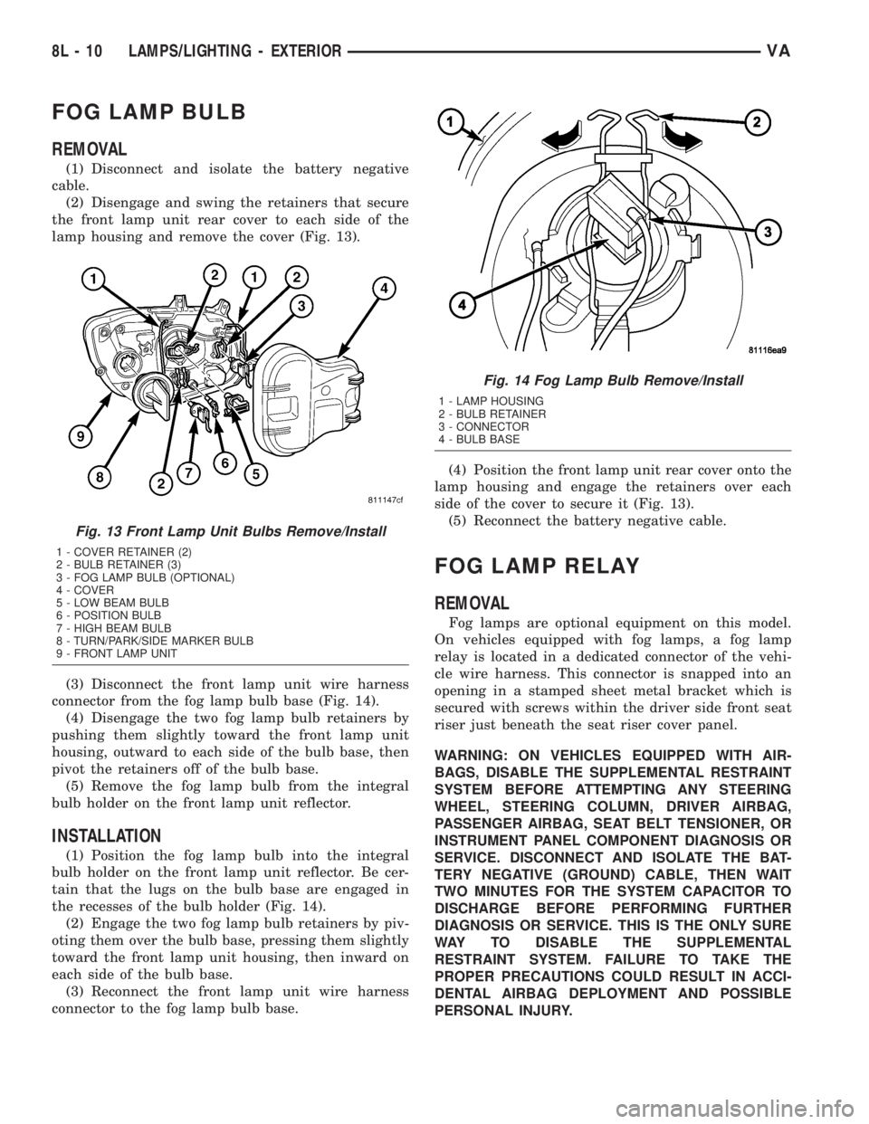
the front lamp unit rear cover to each side of the
lamp housing and remove the cover (Fig. 13).
(3) Disconnect the front lamp unit wire harness
connector from the fog lamp bulb base (Fig. 14).
(4) Disengage the two fog lamp bulb retainers by
pushing them slightly toward the front lamp unit
housing, outward to each side of the bulb base, then
pivot the retainers off of the bulb base.
(5) Remove the fog lamp bulb from the integral
bulb holder on the front lamp unit reflector.
INSTALLATION
(1) Position the fog lamp bulb into the integral
bulb holder on the front lamp unit reflector. Be cer-
tain that the lugs on the bulb base are engaged in
the recesses of the bulb holder (Fig. 14).
(2) Engage the two fog lamp bulb retainers by piv-
oting them over the bulb base, pressing them slightly
toward the front lamp unit housing, then inward on
each side of the bulb base.
(3) Reconnect the front lamp unit wire harness
connector to the fog lamp bulb base.(4) Position the front lamp unit rear cover onto the
lamp housing and engage the retainers over each
side of the cover to secure it (Fig. 13).
(5) Reconnect the battery negative cable.
FOG LAMP RELAY
REMOVAL
Fog lamps are optional equipment on this model.
On vehicles equipped with fog lamps, a fog lamp
relay is located in a dedicated connector of the vehi-
cle wire harness. This connector is snapped into an
opening in a stamped sheet metal bracket which is
secured with screws within the driver side front seat
riser just beneath the seat riser cover panel.
WARNING: ON VEHICLES EQUIPPED WITH AIR-
BAGS, DISABLE THE SUPPLEMENTAL RESTRAINT
SYSTEM BEFORE ATTEMPTING ANY STEERING
WHEEL, STEERING COLUMN, DRIVER AIRBAG,
PASSENGER AIRBAG, SEAT BELT TENSIONER, OR
INSTRUMENT PANEL COMPONENT DIAGNOSIS OR
SERVICE. DISCONNECT AND ISOLATE THE BAT-
TERY NEGATIVE (GROUND) CABLE, THEN WAIT
TWO MINUTES FOR THE SYSTEM CAPACITOR TO
DISCHARGE BEFORE PERFORMING FURTHER
DIAGNOSIS OR SERVICE. THIS IS THE ONLY SURE
WAY TO DISABLE THE SUPPLEMENTAL
RESTRAINT SYSTEM. FAILURE TO TAKE THE
PROPER PRECAUTIONS COULD RESULT IN ACCI-
DENTAL AIRBAG DEPLOYMENT AND POSSIBLE
PERSONAL INJURY.
Fig. 13 Front Lamp Unit Bulbs Remove/Install
1 - COVER RETAINER (2)
2 - BULB RETAINER (3)
3 - FOG LAMP BULB (OPTIONAL)
4 - COVER
5 - LOW BEAM BULB
6 - POSITION BULB
7 - HIGH BEAM BULB
8 - TURN/PARK/SIDE MARKER BULB
9 - FRONT LAMP UNIT
Fig. 14 Fog Lamp Bulb Remove/Install
1 - LAMP HOUSING
2 - BULB RETAINER
3 - CONNECTOR
4 - BULB BASE
8L - 10 LAMPS/LIGHTING - EXTERIORVA
Page 209 of 1232
(1) Disconnect and isolate the battery negative
cable.
(2) Move the driver side front seat to its most for-
ward position for easiest access to the seat riser
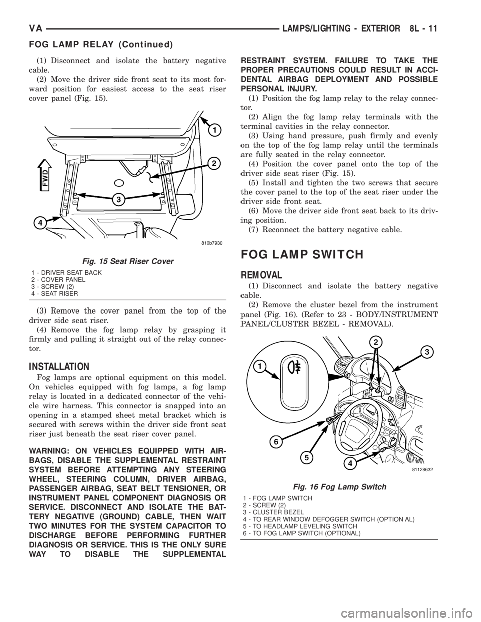
cover panel (Fig. 15).
(3) Remove the cover panel from the top of the
driver side seat riser.
(4) Remove the fog lamp relay by grasping it
firmly and pulling it straight out of the relay connec-
tor.
INSTALLATION
Fog lamps are optional equipment on this model.
On vehicles equipped with fog lamps, a fog lamp
relay is located in a dedicated connector of the vehi-
cle wire harness. This connector is snapped into an
opening in a stamped sheet metal bracket which is
secured with screws within the driver side front seat
riser just beneath the seat riser cover panel.
WARNING: ON VEHICLES EQUIPPED WITH AIR-
BAGS, DISABLE THE SUPPLEMENTAL RESTRAINT
SYSTEM BEFORE ATTEMPTING ANY STEERING
WHEEL, STEERING COLUMN, DRIVER AIRBAG,
PASSENGER AIRBAG, SEAT BELT TENSIONER, OR
INSTRUMENT PANEL COMPONENT DIAGNOSIS OR
SERVICE. DISCONNECT AND ISOLATE THE BAT-
TERY NEGATIVE (GROUND) CABLE, THEN WAIT
TWO MINUTES FOR THE SYSTEM CAPACITOR TO
DISCHARGE BEFORE PERFORMING FURTHER
DIAGNOSIS OR SERVICE. THIS IS THE ONLY SURE
WAY TO DISABLE THE SUPPLEMENTALRESTRAINT SYSTEM. FAILURE TO TAKE THE
PROPER PRECAUTIONS COULD RESULT IN ACCI-
DENTAL AIRBAG DEPLOYMENT AND POSSIBLE
PERSONAL INJURY.
(1) Position the fog lamp relay to the relay connec-
tor.
(2) Align the fog lamp relay terminals with the
terminal cavities in the relay connector.
(3) Using hand pressure, push firmly and evenly
on the top of the fog lamp relay until the terminals
are fully seated in the relay connector.
(4) Position the cover panel onto the top of the
driver side seat riser (Fig. 15).
(5) Install and tighten the two screws that secure
the cover panel to the top of the seat riser under the
driver side front seat.
(6) Move the driver side front seat back to its driv-
ing position.
(7) Reconnect the battery negative cable.
FOG LAMP SWITCH
REMOVAL
(1) Disconnect and isolate the battery negative
cable.
(2) Remove the cluster bezel from the instrument
panel (Fig. 16). (Refer to 23 - BODY/INSTRUMENT
PANEL/CLUSTER BEZEL - REMOVAL).
Fig. 15 Seat Riser Cover
1 - DRIVER SEAT BACK
2 - COVER PANEL
3 - SCREW (2)
4 - SEAT RISER
Fig. 16 Fog Lamp Switch
1 - FOG LAMP SWITCH
2 - SCREW (2)
3 - CLUSTER BEZEL
4 - TO REAR WINDOW DEFOGGER SWITCH (OPTION AL)
5 - TO HEADLAMP LEVELING SWITCH
6 - TO FOG LAMP SWITCH (OPTIONAL)
VALAMPS/LIGHTING - EXTERIOR 8L - 11
FOG LAMP RELAY (Continued)