2005 MERCEDES-BENZ SPRINTER Cool
[x] Cancel search: CoolPage 185 of 1232
ENGINE TEMPERATURE
GAUGE
DESCRIPTION
An engine coolant temperature gauge is standard
equipment on all instrument clusters. The engine
coolant temperature gauge is located in the upper
right corner of the instrument cluster, to the right of
the speedometer. The engine coolant temperature
gauge consists of a movable gauge needle or pointer
controlled by the instrument cluster circuitry and a
fixed 45 degree scale on the cluster overlay that
reads left-to-right from 120É C to 40É C for Canadian
vehicles, or from 250É F to 110É F for United States
vehicles. An International Control and Display Sym-
bol icon for ªEngine Coolant Temperatureº is located
on the cluster overlay, directly below the high end of
the scale. Just to the right of the icon, the nomencla-
ture ªÉCº or ªÉFº confirms the unit of measure for the
gauge readings.
The engine coolant temperature gauge graphics are
white against a black field, except for a single red
graduation at the far left (high) end of the gauge
scale, making them clearly visible within the instru-
ment cluster in daylight. When illuminated from
behind by the panel lamps dimmer controlled cluster
illumination lighting with the exterior lamps turned
On, the white graphics appear amber and the red
graphics appear red. The orange gauge needle is
internally illuminated. Gauge illumination is pro-
vided by Light Emitting Diode (LED) units soldered
onto the instrument cluster electronic circuit board.
The engine coolant temperature gauge is serviced as
a unit with the instrument cluster.
OPERATION
The engine coolant temperature gauge gives an
indication to the vehicle operator of the engine cool-
ant temperature. This gauge is controlled by the
instrument cluster circuit board based upon cluster
programming and electronic messages received by
the cluster from the Engine Control Module (ECM)
over the Controller Area Network (CAN) data bus.
The engine coolant temperature gauge is an air core
magnetic unit that receives battery current on the
instrument cluster electronic circuit board when the
instrument cluster detects that the ignition switch is
in the On position. The cluster is programmed to
move the gauge needle back to the low end of the
scale after the ignition switch is turned to the Off
position. The instrument cluster circuitry controls
the gauge needle position and provides the following
features:
²Engine Temperature Normal Message- Each
time the cluster receives a message from the ECMindicating the engine coolant temperature is within
the normal operating range [up to about 120É C (250É
F), the gauge needle is moved to the actual relative
temperature position on the gauge scale.
²Engine Temperature High Message- Each
time the cluster receives a message from the ECM
indicating the engine coolant temperature is high
[above about 120É C (250É F) the gauge needle is
moved into the red warning zone on the gauge scale.
The ECM continually monitors the engine coolant
temperature sensor to determine the engine operat-
ing temperature. The ECM then sends the proper
engine coolant temperature messages to the instru-
ment cluster. If the instrument cluster moves the
engine coolant temperature gauge needle to red area
of the gauge scale, it may indicate that the engine or
the engine cooling system require service. For proper
diagnosis of the engine coolant temperature sensor,
the ECM, the CAN data bus, the electronic message
inputs to the instrument cluster, or the instrument
cluster circuitry that controls the engine coolant tem-
perature gauge, a DRBIIItscan tool is required.
Refer to the appropriate diagnostic information.
FUEL FILTER CLOGGED
INDICATOR
DESCRIPTION
A fuel filter clogged indicator is standard equip-
ment on all instrument clusters. The fuel filter
clogged indicator is located near the left edge of the
instrument cluster, next to the tachometer. The fuel
filter clogged indicator consists of the International
Control and Display Symbol icon for ªFuel Filterº
imprinted within a rectangular cutout in the opaque
layer of the instrument cluster overlay. The dark
outer layer of the overlay prevents the indicator from
being clearly visible when it is not illuminated. An
amber Light Emitting Diode (LED) behind the cutout
in the opaque layer of the overlay causes the icon to
appear silhouetted against an amber field through
the translucent outer layer of the overlay when the
indicator is illuminated from behind by the LED,
which is soldered onto the instrument cluster elec-
tronic circuit board. The fuel filter clogged indicator
is serviced as a unit with the instrument cluster.
OPERATION
The fuel filter clogged indicator gives an indication
to the vehicle operator when the pressure in the fuel
system is low, which could indicate that the fuel filter
is clogged. This indicator is controlled by a transistor
on the instrument cluster circuit board based upon
cluster programming and electronic messages
received by the cluster from the Engine Control Mod-
VAINSTRUMENT CLUSTER 8J - 15
Page 189 of 1232
ule (ECM) over the Controller Area Network (CAN)
data bus. The low oil level indicator Light Emitting
Diode (LED) is completely controlled by the instru-
ment cluster logic circuit, and that logic will only
allow this indicator to operate when the instrument
cluster detects that the ignition switch is in the On
position. Therefore, the LED will always be off when
the ignition switch is in any position except On. The
LED only illuminates when it is provided a path to
ground by the instrument cluster transistor. The
instrument cluster will turn on the low oil level indi-
cator for the following reasons:
²Bulb Test- Each time the ignition switch is
turned to the On position the low oil level indicator
is illuminated for about two seconds as a bulb test.
²Engine Oil Level Low Message- Once the
engine has been started, each time the cluster
receives a message from the ECM indicating that the
engine oil level is at or near the ªMinimumº mark on
the dipstick, the low oil level indicator is illuminated.
The indicator remains illuminated briefly at first, but
will remain illuminated for longer periods as subse-
quent messages indicate that the oil level has
dropped further. Eventually, the indicator will
remain illuminated solid until the engine oil level is
corrected, or until the ignition switch is turned to the
Off position, whichever occurs first.
The instrument cluster also supplements the oil level
indicator by displaying an engine oil icon along with
alpha-numeric messages in the multi-function indicator
Liquid Crystal Display (LCD) advising the vehicle oper-
ator how much oil is required to correct the engine oil
level, and when the ªMaximumº engine oil level has
been exceeded. See the owner's manual in the vehicle
glove box for more information on this feature.
The ECM continually monitors the engine oil level
and temperature sensor to determine the engine oil
level. The ECM then sends the proper engine oil
level messages to the instrument cluster. If the
instrument cluster turns on the indicator after the
bulb test, even after the engine oil level is sufficient,
it may indicate that the engine or the engine oiling
system requires service. For proper diagnosis of the
engine oil level and temperature sensor, the ECM,
the CAN data bus, or the electronic message inputs
to the instrument cluster that control the low oil
level indicator, a DRBIIItscan tool is required. Refer
to the appropriate diagnostic information.
MAINTENANCE INDICATOR
DESCRIPTION
An Active Service SYSTem (ASSYST) engine oil main-
tenance indicator is optional equipment on all instru-
ment clusters. In vehicles so equipped, a second,dedicated ASSYST microprocessor is integral to the
cluster electronic circuit board. The ASSYST indications
are displayed and can be toggled with the clock indica-
tion on the right side of the multi-function indicator
Liquid Crystal Display (LCD) located near the lower
edge of the instrument cluster, directly below the speed-
ometer. The ASSYST displays include numeric values
combined with several icons to indicate actual engine oil
level, and reminders in time (days) or distance (miles or
kilometers) until the next required engine oil mainte-
nance is anticipated. ASSYST also provides several
audible indications using the electronic tone generator
on the instrument cluster circuit board to supplement
these visual displays.
The indications of the ASSYST engine oil mainte-
nance indicator are not visible when the LCD is not illu-
minated. When illuminated, the ASSYST indications
appear as dark characters and icons silhouetted against
an amber field. When the exterior lighting is turned Off,
the display is illuminated at maximum brightness.
When the exterior lighting is turned On, the display
illumination level can be adjusted in concert with the
cluster general illumination lighting using the ª+º (plus)
and ª2º (minus) multi-function indicator push buttons.
The ASSYST engine oil maintenance indicator is ser-
viced as a unit with the instrument cluster.
OPERATION
The ASSYST engine oil maintenance indicator micro-
processor uses numerous criteria besides time and mile-
age to evaluate vehicle maintenance requirements. Time
data is taken from the electronic digital clock integral to
the instrument cluster. Vehicle distance data is obtained
from the Controller Antilock Brake (CAB) over the Con-
troller Area Network (CAN) data bus. Coolant tempera-
ture, engine oil temperature, engine oil level, engine oil
quality, engine speed, and engine load data are obtained
from the Engine Control Module (ECM) over the CAN
data bus. Using all of the available data and internal
programming, the ASSYST microprocessor then calcu-
lates the estimated time and distance to the next
required engine oil maintenance interval. The ASSYST
uses the multi-function indicator LCD to display that
data and, when necessary, issues audible alerts to the
vehicle operator through the electronic tone generator
on the cluster circuit board.
See the owner's manual in the vehicle glove box for
more information on the features, use, operation and
resetting procedures for the ASSYST maintenance
computer. Proper diagnosis and testing of the
ASSYST engine oil maintenance computer, the CAN
data bus and the electronic data bus message inputs
to the EMIC that are used by the ASSYST computer
for its calculations requires the use of a DRBIIIt
scan tool. Refer to the appropriate diagnostic infor-
mation.
VAINSTRUMENT CLUSTER 8J - 19
LOW OIL LEVEL INDICATOR (Continued)
Page 197 of 1232
the wait-to-start indicator will be illuminated. The
indicator remains illuminated until the cluster
receives a wait-to-start lamp-off message indicating
that the pre-heat mode of the glow plugs has been
completed, until the ECM detects that the engine is
running, or until the ignition switch is turned to the
Off position, whichever occurs first.
The ECM continually monitors the engine coolant
temperature sensor to determine when the glow
plugs need to be energized in their pre-heat operat-
ing mode. The ECM then sends the proper wait-to-
start lamp-on and lamp-off messages to the
instrument cluster. If the instrument cluster turns on
the indicator after the engine is started, it may indi-
cate that a malfunction has occurred and that the
engine glow control system requires service. The
ECM will store a Diagnostic Trouble Code (DTC) for
any malfunction it detects. For proper diagnosis of
the engine coolant temperature sensor, the engine
glow control system and circuits, the ECM, the CAN
data bus, or the electronic message inputs to the
instrument cluster that control the wait-to-start indi-
cator, a DRBIIItscan tool is required. Refer to the
appropriate diagnostic information.
WASHER FLUID INDICATOR
DESCRIPTION
A washer fluid indicator is standard equipment on
all instrument clusters. However, this indicator is
only functional on vehicles equipped with an optional
washer fluid level switch integral to the washer
pump/motor unit on the washer reservoir. The
washer fluid indicator is located near the lower edge
of the instrument cluster, to the right of the multi-
function indicator display. The washer fluid indicator
consists of the International Control and Display
Symbol icon for ªWindshield Washer Fluidº imprinted
within a rectangular cutout in the opaque layer of
the instrument cluster overlay. The dark outer layer
of the overlay prevents the indicator from being
clearly visible when it is not illuminated. An amber
Light Emitting Diode (LED) behind the cutout in the
opaque layer of the overlay causes the icon to appear
silhouetted against an amber field through the trans-
lucent outer layer of the overlay when the indicator
is illuminated from behind by the LED, which is sol-
dered onto the instrument cluster electronic circuit
board. The washer fluid indicator is serviced as a
unit with the instrument cluster.
OPERATION
The washer fluid indicator gives an indication to
the vehicle operator that the fluid level in the washer
reservoir is low. This indicator is controlled by theinstrument cluster circuit board based upon cluster
programming and a hard wired input from the
optional washer fluid level switch that is integral to
the washer pump/motor unit. The washer fluid indi-
cator is completely controlled by the instrument clus-
ter logic circuit, and that logic will only allow this
indicator to operate when the instrument cluster
detects that the ignition switch is in the On position.
Therefore, the indicator will always be off when the
ignition switch is in any position except On. The indi-
cator only illuminates when it is switched to ground
by the instrument cluster circuitry. The instrument
cluster will turn on the washer fluid indicator for the
following reasons:
²Bulb Test- Each time the ignition switch is
turned to the On position the brake wear indicator is
illuminated by the instrument cluster for about two
seconds as a bulb test.
²Washer Fluid Level Switch Input- Each time
the cluster detects ground on the washer fluid switch
sense circuit (washer fluid level switch closed =
washer fluid level low) while the ignition switch is in
the On position, the washer fluid indicator is illumi-
nated. The indicator remains illuminated until the
washer fluid level switch input to the cluster is an
open circuit (washer fluid level switch open = washer
fluid level acceptable), or until the ignition switch is
turned to the Off position, whichever occurs first.
The instrument cluster continually monitors the
washer fluid level switch to determine the level of
the washer fluid. The instrument cluster logic applies
a delay strategy to this input to reduce the negative
effect that fluid sloshing within the reservoir can
have on reliable indicator operation. The washer
fluid level switch and circuit can be diagnosed using
conventional diagnostic tools and methods. For
proper diagnosis of the instrument cluster circuitry
that controls the washer fluid indicator, a DRBIIIt
scan tool is required. Refer to the appropriate diag-
nostic information.
WATER-IN-FUEL INDICATOR
DESCRIPTION
A water-in-fuel indicator is standard equipment in
all instrument clusters. The water-in-fuel indicator is
located near the lower edge of the instrument cluster,
to the left of the multi-function indicator display. The
water-in-fuel indicator consists of the International
Control and Display Symbol icon for ªWater In Fuelº
imprinted within a rectangular cutout in the opaque
layer of the instrument cluster overlay. The dark
outer layer of the overlay prevents the indicator from
being clearly visible when it is not illuminated. An
amber Light Emitting Diode (LED) behind the cutout
VAINSTRUMENT CLUSTER 8J - 27
WAIT-TO-START INDICATOR (Continued)
Page 245 of 1232
WARNING: IF YOU EXPERIENCE SKIN IRRITATION
DURING CLEANUP, RUN COOL WATER OVER THE
AFFECTED AREA. ALSO, IF YOU EXPERIENCE
IRRITATION OF THE NOSE OR THROAT, EXIT THE
VEHICLE FOR FRESH AIR UNTIL THE IRRITATION
CEASES. IF IRRITATION CONTINUES, SEE A PHYSI-
CIAN.
(1) Begin the cleanup by using a vacuum cleaner
to remove any residual powder from the vehicle inte-
rior. Clean from outside the vehicle and work your
way inside, so that you avoid kneeling or sitting on a
non-cleaned area.
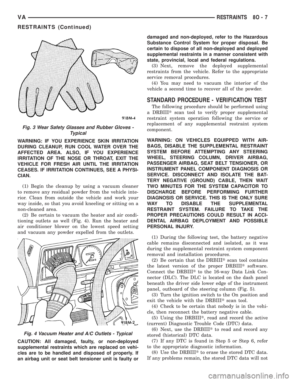
(2) Be certain to vacuum the heater and air condi-
tioning outlets as well (Fig. 4). Run the heater and
air conditioner blower on the lowest speed setting
and vacuum any powder expelled from the outlets.
CAUTION: All damaged, faulty, or non-deployed
supplemental restraints which are replaced on vehi-
cles are to be handled and disposed of properly. If
an airbag unit or seat belt tensioner unit is faulty ordamaged and non-deployed, refer to the Hazardous
Substance Control System for proper disposal. Be
certain to dispose of all non-deployed and deployed
supplemental restraints in a manner consistent with
state, provincial, local and federal regulations.
(3) Next, remove the deployed supplemental
restraints from the vehicle. Refer to the appropriate
service removal procedures.
(4) You may need to vacuum the interior of the
vehicle a second time to recover all of the powder.
STANDARD PROCEDURE - VERIFICATION TEST
The following procedure should be performed using
a DRBIIItscan tool to verify proper supplemental
restraint system operation following the service or
replacement of any supplemental restraint system
component.
WARNING: ON VEHICLES EQUIPPED WITH AIR-
BAGS, DISABLE THE SUPPLEMENTAL RESTRAINT
SYSTEM BEFORE ATTEMPTING ANY STEERING
WHEEL, STEERING COLUMN, DRIVER AIRBAG,
PASSENGER AIRBAG, SEAT BELT TENSIONER, OR
INSTRUMENT PANEL COMPONENT DIAGNOSIS OR
SERVICE. DISCONNECT AND ISOLATE THE BAT-
TERY NEGATIVE (GROUND) CABLE, THEN WAIT
TWO MINUTES FOR THE SYSTEM CAPACITOR TO
DISCHARGE BEFORE PERFORMING FURTHER
DIAGNOSIS OR SERVICE. THIS IS THE ONLY SURE
WAY TO DISABLE THE SUPPLEMENTAL
RESTRAINT SYSTEM. FAILURE TO TAKE THE
PROPER PRECAUTIONS COULD RESULT IN ACCI-
DENTAL AIRBAG DEPLOYMENT AND POSSIBLE
PERSONAL INJURY.
(1) During the following test, the battery negative
cable remains disconnected and isolated, as it was
during the supplemental restraint system component
removal and installation procedures.
(2) Be certain that the DRBIIItscan tool contains
the latest version of the proper DRBIIItsoftware.
Connect the DRBIIItto the 16-way Data Link Con-
nector (DLC). The DLC is located on the dash panel
beneath the driver side lower edge of the instrument
panel, outboard of the steering column (Fig. 5).
(3) Turn the ignition switch to the On position and
exit the vehicle with the DRBIIItscan tool.
(4) Check to be certain that nobody is in the vehi-
cle, then reconnect the battery negative cable.
(5) Using the DRBIIIt, read and record the active
(current) Diagnostic Trouble Code (DTC) data.
(6) Next, use the DRBIIItto read and record any
stored (historical) DTC data.
(7) If any DTC is found in Step 5 or Step 6, refer
to the appropriate diagnostic information.
(8) Use the DRBIIItto erase the stored DTC data.
If any problems remain, the stored DTC data will not
Fig. 3 Wear Safety Glasses and Rubber Gloves -
Typical
Fig. 4 Vacuum Heater and A/C Outlets - Typical
VARESTRAINTS 8O - 7
RESTRAINTS (Continued)
Page 255 of 1232
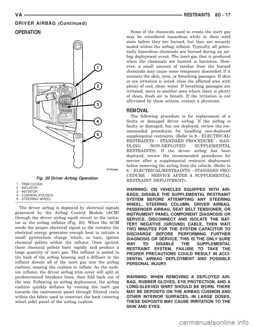
OPERATION
The driver airbag is deployed by electrical signals
generated by the Airbag Control Module (ACM)
through the driver airbag squib circuit to the initia-
tor in the airbag inflator (Fig. 20). When the ACM
sends the proper electrical signal to the initiator the
electrical energy generates enough heat to initiate a
small pyrotechnic charge which, in turn, ignites
chemical pellets within the inflator. Once ignited,
these chemical pellets burn rapidly and produce a
large quantity of inert gas. The inflator is sealed to
the back of the airbag housing and a diffuser in the
inflator directs all of the inert gas into the airbag
cushion, causing the cushion to inflate. As the cush-
ion inflates, the driver airbag trim cover will split at
predetermined breakout lines, then fold back out of
the way. Following an airbag deployment, the airbag
cushion quickly deflates by venting the inert gas
towards the instrument panel through filtered vents
within the fabric used to construct the back (steering
wheel side) panel of the airbag cushion.Some of the chemicals used to create the inert gas
may be considered hazardous while in their solid
state before they are burned, but they are securely
sealed within the airbag inflator. Typically, all poten-
tially hazardous chemicals are burned during an air-
bag deployment event. The inert gas that is produced
when the chemicals are burned is harmless. How-
ever, a small amount of residue from the burned
chemicals may cause some temporary discomfort if it
contacts the skin, eyes, or breathing passages. If skin
or eye irritation is noted, rinse the affected area with
plenty of cool, clean water. If breathing passages are
irritated, move to another area where there is plenty
of clean, fresh air to breath. If the irritation is not
alleviated by these actions, contact a physician.
REMOVAL
The following procedure is for replacement of a
faulty or damaged driver airbag. If the airbag is
faulty or damaged, but not deployed, review the rec-
ommended procedures for handling non-deployed
supplemental restraints. (Refer to 8 - ELECTRICAL/
RESTRAINTS - STANDARD PROCEDURE - HAN-
DLING NON-DEPLOYED SUPPLEMENTAL
RESTRAINTS). If the driver airbag has been
deployed, review the recommended procedures for
service after a supplemental restraint deployment
before removing the airbag from the vehicle. (Refer to
8 - ELECTRICAL/RESTRAINTS - STANDARD PRO-
CEDURE - SERVICE AFTER A SUPPLEMENTAL
RESTRAINT DEPLOYMENT).
WARNING: ON VEHICLES EQUIPPED WITH AIR-
BAGS, DISABLE THE SUPPLEMENTAL RESTRAINT
SYSTEM BEFORE ATTEMPTING ANY STEERING
WHEEL, STEERING COLUMN, DRIVER AIRBAG,
PASSENGER AIRBAG, SEAT BELT TENSIONER, OR
INSTRUMENT PANEL COMPONENT DIAGNOSIS OR
SERVICE. DISCONNECT AND ISOLATE THE BAT-
TERY NEGATIVE (GROUND) CABLE, THEN WAIT
TWO MINUTES FOR THE SYSTEM CAPACITOR TO
DISCHARGE BEFORE PERFORMING FURTHER
DIAGNOSIS OR SERVICE. THIS IS THE ONLY SURE
WAY TO DISABLE THE SUPPLEMENTAL
RESTRAINT SYSTEM. FAILURE TO TAKE THE
PROPER PRECAUTIONS COULD RESULT IN ACCI-
DENTAL AIRBAG DEPLOYMENT AND POSSIBLE
PERSONAL INJURY.
WARNING: WHEN REMOVING A DEPLOYED AIR-
BAG, RUBBER GLOVES, EYE PROTECTION, AND A
LONG-SLEEVED SHIRT SHOULD BE WORN. THERE
MAY BE DEPOSITS ON THE AIRBAG CUSHION AND
OTHER INTERIOR SURFACES. IN LARGE DOSES,
THESE DEPOSITS MAY CAUSE IRRITATION TO THE
SKIN AND EYES.
Fig. 20 Driver Airbag Operation
1 - TRIM COVER
2 - INFLATOR
3 - INITIATOR
4 - CUSHION (FOLDED)
5 - STEERING WHEEL
VARESTRAINTS 8O - 17
DRIVER AIRBAG (Continued)
Page 262 of 1232
The passenger airbag unit used in this model is a
Next Generation-type that complies with revised fed-
eral airbag standards to deploy with less force than
those used in some prior models. The airbag housing
contains the folded airbag cushion, the airbag
retainer, and the airbag inflator. The airbag is a rect-
angular fabric cushion. The airbag inflator is a solid
fuel, pyrotechnic-type unit that is secured to and
sealed within the airbag housing along with the
folded airbag cushion. The inflator initiator connector
receptacle is connected to the vehicle electrical sys-
tem through a dedicated take out of the vehicle wire
harness with a yellow connector insulator.
The passenger airbag and airbag door unit cannot
be repaired, and must be replaced if deployed, faulty
or in any way damaged.
OPERATION
The passenger airbag is deployed by an electrical
signal generated by the Airbag Control Module
(ACM) through the passenger airbag squib circuits to
the initiator in the airbag inflator. When the ACM
sends the proper electrical signal to the initiator the
electrical energy generates enough heat to initiate a
small pyrotechnic charge which, in turn, ignites
chemical pellets within the inflator. Once ignited,
these chemical pellets burn rapidly and produce a
large quantity of inert gas. The inflator is sealed to
the back of the airbag housing and a diffuser in the
inflator directs all of the inert gas into the airbag
cushion, causing the cushion to inflate.
As the airbag cushion inflates, the passenger air-
bag door will unsnap from the clips that retain it to
the instrument panel at the top and bottom, then
pivot towards the top of the instrument panel and
out of the way on the woven straps. Following a pas-
senger airbag deployment, the airbag cushion quickly
deflates by venting the inert gas through the loose
weave of the fabric used to construct the back
(instrument panel side) of the airbag cushion.
Some of the chemicals used to create the inert gas
may be considered hazardous while in their solid
state before they are burned, but they are securely
sealed within the airbag inflator. However, the gas
that is produced when the chemicals are burned is
harmless. A small amount of residue from the burned
chemicals may cause some temporary discomfort if it
contacts the skin, eyes, or breathing passages. If skin
or eye irritation is noticed, rinse the affected area
with plenty of cool, clean water. If breathing pas-
sages are irritated, move to another area where there
is plenty of clean, fresh air to breath. If the irritation
is not alleviated by these actions, contact a physician
immediately.
REMOVAL
The following procedure is for replacement of a
faulty or damaged passenger airbag. If the airbag is
faulty or damaged, but not deployed, review the rec-
ommended procedures for handling non-deployed
supplemental restraints. (Refer to 8 - ELECTRICAL/
RESTRAINTS - STANDARD PROCEDURE - HAN-
DLING NON-DEPLOYED SUPPLEMENTAL
RESTRAINTS). If the passenger airbag has been
deployed, review the recommended procedures for
service after a supplemental restraint deployment
before removing the airbag from the vehicle. (Refer to
8 - ELECTRICAL/RESTRAINTS - STANDARD PRO-
CEDURE - SERVICE AFTER A SUPPLEMENTAL
RESTRAINT DEPLOYMENT).
WARNING: ON VEHICLES EQUIPPED WITH AIR-
BAGS, DISABLE THE SUPPLEMENTAL RESTRAINT
SYSTEM BEFORE ATTEMPTING ANY STEERING
WHEEL, STEERING COLUMN, DRIVER AIRBAG,
PASSENGER AIRBAG, SEAT BELT TENSIONER, OR
INSTRUMENT PANEL COMPONENT DIAGNOSIS OR
SERVICE. DISCONNECT AND ISOLATE THE BAT-
TERY NEGATIVE (GROUND) CABLE, THEN WAIT
TWO MINUTES FOR THE SYSTEM CAPACITOR TO
DISCHARGE BEFORE PERFORMING FURTHER
DIAGNOSIS OR SERVICE. THIS IS THE ONLY SURE
WAY TO DISABLE THE SUPPLEMENTAL
RESTRAINT SYSTEM. FAILURE TO TAKE THE
PROPER PRECAUTIONS COULD RESULT IN ACCI-
DENTAL AIRBAG DEPLOYMENT AND POSSIBLE
PERSONAL INJURY.
WARNING: WHEN REMOVING A DEPLOYED AIR-
BAG, RUBBER GLOVES, EYE PROTECTION, AND A
LONG-SLEEVED SHIRT SHOULD BE WORN. THERE
MAY BE DEPOSITS ON THE AIRBAG UNIT AND
OTHER INTERIOR SURFACES. IN LARGE DOSES,
THESE DEPOSITS MAY CAUSE IRRITATION TO THE
SKIN AND EYES.
(1) Disconnect and isolate the battery negative
cable. Wait two minutes for the system capacitor to
discharge before further service.
(2) Remove the instrument panel top cover tray
from over the passenger airbag (Fig. 29). (Refer to 23
- BODY/INSTRUMENT PANEL/INSTRUMENT
PANEL TOP COVER - TRAY - REMOVAL).
(3) Remove the two screws that secure the passen-
ger airbag door upper clips to the instrument panel
base trim.
8O - 24 RESTRAINTSVA
PASSENGER AIRBAG (Continued)
Page 317 of 1232
8W-02 COMPONENT INDEX
Component Page
A/C Auxiliary Fan Relay................ 8W-42
A/C Auxiliary Fan..................... 8W-42
A/C Compressor Clutch................. 8W-42
A/C Control Module-Roof................ 8W-42
A/C Fan Switch....................... 8W-42
A/C Switch-Roof...................... 8W-42
Accelerator Pedal Position Sensor......... 8W-30
Air Outlet Temperature Sensor........... 8W-42
Airbag Control Module................. 8W-43
Airbag Squibs........................ 8W-43
Ambient Temperature Sensor............ 8W-42
Ash Receiver Lamp.................... 8W-44
Automatic Temperature Control Module.... 8W-42
Auxiliary Heater Relay................. 8W-42
Auxiliary Heater Switch................ 8W-42
Battery Relay-Auxiliary................ 8W-20
Batteries............................ 8W-20
Beam Select Switch.................... 8W-50
Blower Motors........................ 8W-42
Body Plug Connector................... 8W-11
Boost Pressure Sensor.................. 8W-30
Boost Pressure Solenoid................ 8W-30
Brake Fluid Level Switch............... 8W-35
Brake Lamp Switch.................... 8W-35
Brake Wear Sensors................... 8W-35
Cabin Heater Assembly................. 8W-42
Cabin Heater Control Module............ 8W-42
Camshaft Position Sensor............... 8W-30
Center High Mounted Stop Lamp......... 8W-51
Central Timer Module.................. 8W-45
Cigar Lighter Lamp................... 8W-44
Cigar Lighter......................... 8W-41
Circulation Pump Diode................ 8W-42
Circulation Pump Relay................ 8W-42
Circulation Pump..................... 8W-42
Clockspring....................... 8W-41, 43
Contact Switch Door-Tailgate............ 8W-44
Controller Antilock Brake............... 8W-35
Courtesy Lamps...................... 8W-44
Crankcase Heater..................... 8W-30
Crankshaft Position Sensor.............. 8W-30
Ctel Antenna Connector................ 8W-55
Ctel Connector..................... 8W-47, 55
Cylinder Lock Switch-Driver............. 8W-61
D+ Relay No. 1....................... 8W-10
D+ Relay No. 2....................... 8W-11
Data Link Connector................... 8W-18
Daytime Running Lamp Relays........... 8W-50
Differential Lock Solenoid Valve.......... 8W-31
Dome Lamp.......................... 8W-44
Door Jamb Switches................... 8W-44
Door Lock Motor/Ajar Switch Assemblies . . . 8W-61Component Page
Dosing Pump......................... 8W-42
EGR Valve........................... 8W-30
Engine Control Module................. 8W-30
Engine Control Relay.................. 8W-31
Engine Coolant Level Switch............. 8W-30
Engine Coolant Temperature Sensor....... 8W-30
Engine Oil Sensor..................... 8W-30
Evaporator Temperature Sensor.......... 8W-42
Fan Stage 1 Relay..................... 8W-42
Fog Lamp Relay...................... 8W-50
Fog Lamp Switch..................... 8W-50
Fuel Injectors........................ 8W-30
Fuel Level Sensor..................... 8W-30
Fuel Pressure Sensor.................. 8W-30
Fuel Pressure Solenoid................. 8W-30
Fuel Shutdown Solenoid................ 8W-30
Fuel Temperature Sensor............... 8W-30
Fuses............................ 8W-10, 11
Fuse Blocks.......................... 8W-10
Fuse/Relay Block...................... 8W-11
Fused Ignition Switch Run-Start Relay..... 8W-11
Grounds............................ 8W-70
Generator........................... 8W-20
Glow Plug Control Module.............. 8W-30
Glow Plugs.......................... 8W-30
Hazard Warning Switch................ 8W-52
Headlamp Adjust Switch................ 8W-50
Headlamp Assemblies............... 8W-50, 52
Headlamp Switch..................... 8W-50
Heat Exchanger Connector.............. 8W-42
Heat Exchanger Switch................. 8W-42
Heated Seat Modules.................. 8W-63
Heated Seat Switches.................. 8W-63
Heater Timer-Auxiliary................. 8W-42
Hood Ajar Switch..................... 8W-39
Horn Relay.......................... 8W-41
Horn Switch......................... 8W-41
Horn............................... 8W-41
Ignition Lock Switch................... 8W-40
Ignition Switch....................... 8W-10
Instrument Cluster.................... 8W-40
Instrument Panel Socket................ 8W-40
Intake Air Temperature Sensor........... 8W-30
Interior Lamps....................... 8W-44
Interior Light Switches................. 8W-44
Interior Lighting Connector.............. 8W-44
Intrusion Sensors..................... 8W-39
Kickdown Switch...................... 8W-30
Lamp Relays......................... 8W-50
License Plate Lamps................... 8W-51
Locker Switches...................... 8W-31
Low Fuel Pressure Sensor............... 8W-30
VA8W-02 COMPONENT INDEX 8W - 02 - 1
Page 393 of 1232
8W-15 GROUND DISTRIBUTION
Component PageA/C Auxiliary Fan........................8W-15-4
A/C Auxiliary Fan Relay...................8W-15-12
A/C Control Module- Roof..................8W-15-28
A/C Fan Switch........................8W-15-21
A/C Switch- Roof.....................8W-15-24, 28
Airbag Control Module....................8W-15-11
Ash Receiver Lamp......................8W-15-22
Automatic Temperature Control Module.........8W-15-24
Auxiliary Heater Relay....................8W-15-12
Auxiliary Heater Switch...................8W-15-24
Battery..............................8W-15-8
Battery Relay- Auxiliary...................8W-15-11
Battery- Auxiliary.......................8W-15-11
Blower Motor- Front......................8W-15-9
Brake Fluid Level Switch...................8W-15-8
Brake Wear Sensor- Left Front................8W-15-8
Brake Wear Sensor- Left Rear...............8W-15-28
Brake Wear Sensor- Right Front...............8W-15-8
Brake Wear Sensor- Right Rear...............8W-15-28
Cabin Heater Assembly....................8W-15-3
Center High Mounted Stop Lamp..............8W-15-6
Central Timer Module....................8W-15-15
Cigar Lighter..........................8W-15-22
Cigar Lighter Lamp......................8W-15-22
Circulation Pump........................8W-15-9
Circulation Pump Relay...................8W-15-12
Clockspring...........................8W-15-10
Controller Antilock Brake.................8W-15-2, 28
CTEL Connector........................8W-15-21
Cylinder Lock Switch- Driver..............8W-15-7, 10
D+ Relay No. 1.........................8W-15-12
D+ Relay No. 2.........................8W-15-14
Data Link Connector.....................8W-15-10
Daytime Running Lamp Relay- Left Side.........8W-15-13
Daytime Running Lamp Relay- Right Side........8W-15-13
Daytime Running Lamps Relay...............8W-15-13
Differential Lock Solenoid Valve...............8W-15-2
Dome Lamp...........................8W-15-6
Dosing Pump...........................8W-15-2
Engine Control Module.....................8W-15-7
Engine Coolant Level Switch.................8W-15-2
Fan Stage 1 Relay.......................8W-15-11
Fog Lamp Relay........................8W-15-11
Fog Lamp Switch.......................8W-15-22
Fuse Block No. 1........................8W-15-7
Fused Ignition Switch Run-Start Relay..........8W-15-14
G100..............................8W-15-2, 3
G101................................8W-15-4
G102................................8W-15-4
G200.........................8W-15-6, 7, 8, 9, 10
G201...............................8W-15-11
G202.............8W-15-11, 12, 13, 14, 15, 16, 17, 18, 19
G203....................8W-15-20, 21, 22, 23, 24, 25
G300..........................8W-15-26, 27, 28
G301...............................8W-15-28
G302...............................8W-15-28
Glow Plug Control Module..................8W-15-2
Hazard Warning Switch....................8W-15-7
Headlamp Adjust Switch...................8W-15-22
Headlamp Assembly- Left...................8W-15-3
Headlamp Assembly- Right..................8W-15-4
Heat Exchanger Connector.................8W-15-12
Heat Exchanger Switch....................8W-15-24
Heated Seat Switch- Driver.................8W-15-25
Heated Seat Switch- Passenger...............8W-15-25
Heater Timer- Auxiliary...................8W-15-24
Hood Ajar Switch........................8W-15-4
Horn Relay...........................8W-15-11
Horn Switch..........................8W-15-10
Ignition Lock Switch.....................8W-15-10
Instrument Cluster......................8W-15-10
Instrument Panel Socket...................8W-15-20Component PageInterior Lamp No. 1......................8W-15-6
Interior Lamp No. 2......................8W-15-6
Interior Lamp No. 3......................8W-15-6
Interior Lamp No. 4......................8W-15-6
Interior Lamp No. 5......................8W-15-6
Interior Lamp- Middle Front................8W-15-5, 6
Interior Lamp- Middle Rear................8W-15-5, 6
Interior Lamp- Rear No. 2...................8W-15-5
Interior Lamp- Right Side.................8W-15-5, 6
Interior Light Switch.....................8W-15-21
Interior Lighting Connector..................8W-15-6
Intrusion Sensor No. 1.....................8W-15-6
Intrusion Sensor No. 2.....................8W-15-6
Intrusion Sensor No. 3.....................8W-15-6
Lamp Relay- Left.......................8W-15-13
Lamp Relay- Right......................8W-15-13
License Plate Lamp No. 1..................8W-15-27
License Plate Lamp No. 2..................8W-15-27
Locker Switch No. 1......................8W-15-20
Map/Reading Lamp Switch.................8W-15-21
Marker Lamp Connector...................8W-15-17
Marker Lamp No. 1- Left Front...............8W-15-16
Marker Lamp No. 1- Right Front..............8W-15-16
Marker Lamp No. 2- Left Front...............8W-15-16
Marker Lamp No. 2- Right Front..............8W-15-16
Marker Lamp- Left Center..................8W-15-17
Marker Lamp- Left Rear...................8W-15-27
Marker Lamp- Right Center.................8W-15-17
Marker Lamp- Right Rear..................8W-15-27
Master Door Lock Switch..................8W-15-25
Metering Pump.........................8W-15-18
Multi- Function Switch.....................8W-15-7
Optional Equipment Relay..................8W-15-19
Panic Alarm Switch......................8W-15-20
Parking Brake Switch....................8W-15-15
Power Mirror Motor- Driver.................8W-15-23
Power Mirror Motor- Passenger...............8W-15-23
Power Mirror Switch.....................8W-15-23
Power Window Switch- Driver...............8W-15-23
Power Window Switch- Master...............8W-15-23
Radio...............................8W-15-21
Reading Lamp Connector...................8W-15-6
Recirculated Air Solenoid Valve...............8W-15-9
Seat Belt Switch........................8W-15-15
Security System Module...................8W-15-15
Sentry Key Remote Entry Module..............8W-15-7
Shifter Assembly........................8W-15-20
Siren................................8W-15-9
Tail Lamp Assembly- Left..................8W-15-26
Tail Lamp Assembly- Right.................8W-15-26
TCS Switch...........................8W-15-25
Time Delay Relay.......................8W-15-17
Towing/Intrusion Sensor On/Off Switch..........8W-15-22
Trailer Tow Connector....................8W-15-28
Trailer Tow Control Module.................8W-15-19
Transmission Control Module................8W-15-19
Transmission Relay......................8W-15-19
Turn Signal No. 1- Left Front.................8W-15-3
Turn Signal No. 1- Right Front................8W-15-4
Turn Signal No. 2- Left Front.................8W-15-3
Warm Air Auxiliary Heater Assembly...........8W-15-18
Washer Pump Motor- Front..................8W-15-4
Water Cycle Valve........................8W-15-9
Window Defogger Module- Rear..............8W-15-15
Window Defogger Relay- Left Rear.............8W-15-14
Window Defogger Relay- Right Rear............8W-15-14
Window Defogger Switch- Rear...............8W-15-20
Window Defogger- Left Rear.................8W-15-26
Window Defogger- Right Rear................8W-15-26
Wiper Motor- Front.......................8W-15-9
Wiper/Turn Signal/Engine Start Control Module.....8W-15-7
VA8W-15 GROUND DISTRIBUTION 8W - 15 - 1