2005 MERCEDES-BENZ SPRINTER Cool
[x] Cancel search: CoolPage 19 of 1232
²Engine cooling system. Check corrosion inhibi-
tor/antifreeze, refill as necessary.
²Hydraulic brake system
²Battery
²Windshield washer system
Engine
²Fuel filter renewal
²Air cleaner with maintenance indicator:
²Check degree of contamination.
²Air cleaner filter element renewed as necessary.
Chassis and body
²Trailer coupling:
Check operation, play and retaining fixtures
²Secondary rubber springs:
Visual check
²Tire pressures:
Correct as necessary, including spare tire
²Check thickness of brake pads
²Brake test
²Check condition of steering mechanism
²Heating/ventilation dust filter renewal
ADDITIONAL MAINTENANCE WORK
Automatic transmission once only at 80,000
miles/128000 km
Oil and filter change
During every second maintenance service
Air cleaner without maintenance indicator:
Air cleaner filter element renewal
Check poly-V-belt for wear and signs of damage
During every 6th maintenance service
Rear axle
ADDITIONAL MAINTENANCE WORK AFTER YEARS
Every 3 years
Air cleaner filter element renewal (note installa-
tion date)
Every 5 years or 100,000 miles
Coolant renewal
Note coolant composition
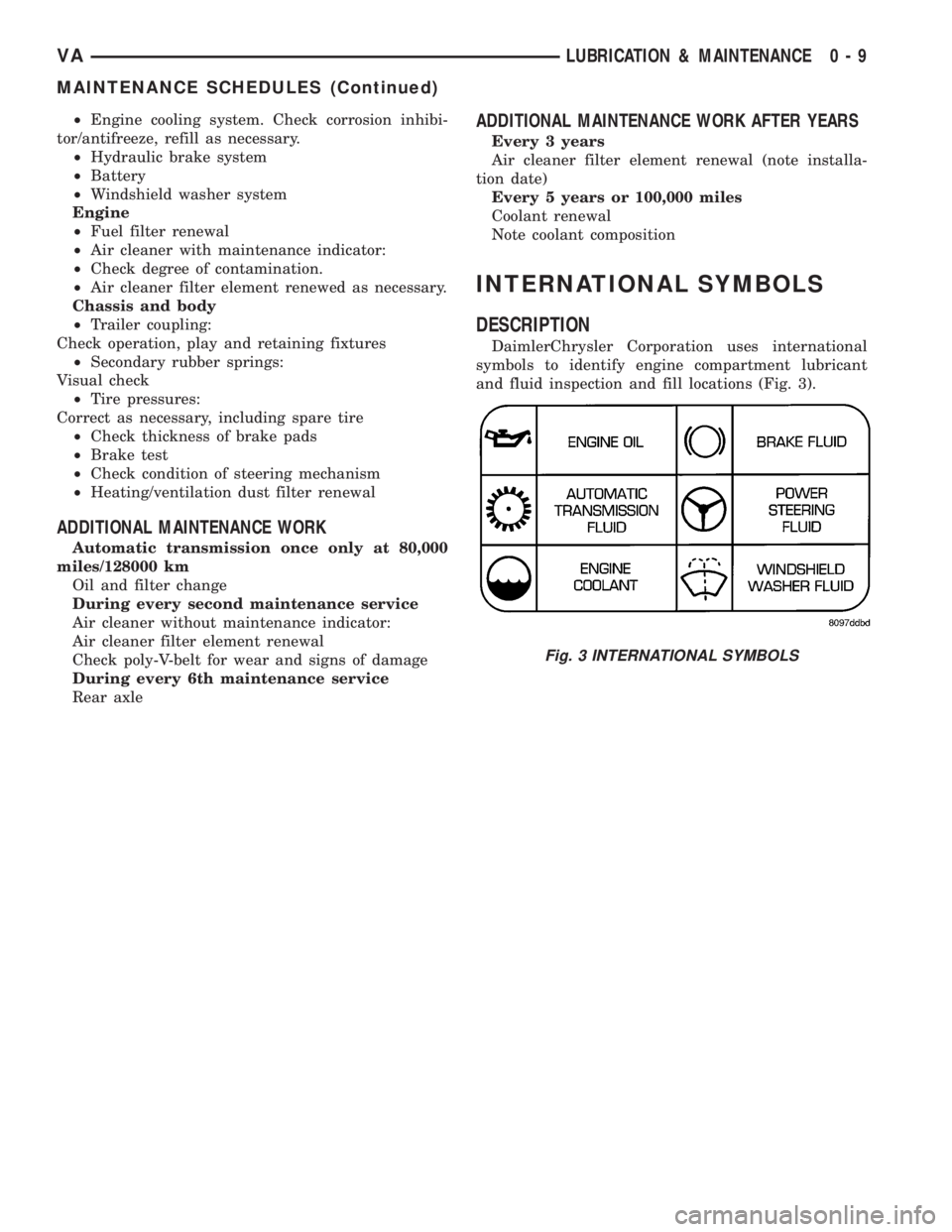
INTERNATIONAL SYMBOLS
DESCRIPTION
DaimlerChrysler Corporation uses international
symbols to identify engine compartment lubricant
and fluid inspection and fill locations (Fig. 3).
Fig. 3 INTERNATIONAL SYMBOLS
VALUBRICATION & MAINTENANCE 0 - 9
MAINTENANCE SCHEDULES (Continued)
Page 67 of 1232
ROAD TESTING
(1) If complaint involved low brake pedal, pump
pedal and note if it comes back up to normal height.
(2) Check brake pedal response with transmission
in Neutral and engine running. Pedal should remain
firm under constant foot pressure.
(3) During road test, make normal and firm brake
stops in 25-40 mph range. Note faulty brake opera-
tion such as low pedal, hard pedal, fade, pedal pulsa-
tion, pull, grab, drag, noise, etc.
(4) Attempt to stop the vehicle with the parking
brake only and note grab, drag, noise, etc.
PEDAL FALLS AWAY
A brake pedal that falls away under steady foot
pressure is generally the result of a system leak. The
leak point could be at a brake line, fitting, hose, or
caliper/wheel cylinder. If leakage is severe, fluid will
be evident at or around the leaking component.
Internal leakage (seal by-pass) in the master cylin-
der caused by worn or damaged piston cups, may
also be the problem cause.
An internal leak in the ABS or RWAL system may
also be the problem with no physical evidence.
LOW PEDAL
If a low pedal is experienced, pump the pedal sev-
eral times. If the pedal comes back up worn linings,
rotors, drums, or rear brakes out of adjustment are
the most likely causes. The proper course of action is
to inspect and replace all worn component and make
the proper adjustments.
SPONGY PEDAL
A spongy pedal is most often caused by air in the
system. However, thin brake drums or substandard
brake lines and hoses can also cause a spongy pedal.
The proper course of action is to bleed the system,
and replace thin drums and substandard quality
brake hoses if suspected.
HARD PEDAL OR HIGH PEDAL EFFORT
A hard pedal or high pedal effort may be due to
lining that is water soaked, contaminated, glazed, or
badly worn. The power booster or check valve could
also be faulty.
PEDAL PULSATION
Pedal pulsation is caused by components that are
loose, or beyond tolerance limits.
The primary cause of pulsation are disc brake
rotors with excessive lateral runout or thickness vari-
ation, or out of round brake drums. Other causes are
loose wheel bearings or calipers and worn, damaged
tires.NOTE: Some pedal pulsation may be felt during
ABS activation.
BRAKE DRAG
Brake drag occurs when the lining is in constant
contact with the rotor or drum. Drag can occur at one
wheel, all wheels, fronts only, or rears only.
Drag is a product of incomplete brake shoe release.
Drag can be minor or severe enough to overheat the
linings, rotors and drums.
Minor drag will usually cause slight surface char-
ring of the lining. It can also generate hard spots in
rotors and drums from the overheat-cool down pro-
cess. In most cases, the rotors, drums, wheels and
tires are quite warm to the touch after the vehicle is
stopped.
Severe drag can char the brake lining all the way
through. It can also distort and score rotors and
drums to the point of replacement. The wheels, tires
and brake components will be extremely hot. In
severe cases, the lining may generate smoke as it
chars from overheating.
Common causes of brake drag are:
²Seized or improperly adjusted parking brake
cables.
²Loose/worn wheel bearing.
²Seized caliper or wheel cylinder piston.
²Caliper binding on corroded bushings or rusted
slide surfaces.
²Loose caliper mounting.
²Drum brake shoes binding on worn/damaged
support plates.
²Mis-assembled components.
²Long booster output rod.
If brake drag occurs at all wheels, the problem
may be related to a blocked master cylinder return
port, or faulty power booster (binds-does not release).
BRAKE FADE
Brake fade is usually a product of overheating
caused by brake drag. However, brake overheating
and resulting fade can also be caused by riding the
brake pedal, making repeated high deceleration stops
in a short time span, or constant braking on steep
mountain roads. Refer to the Brake Drag information
in this section for causes.
BRAKE PULL
Front brake pull condition could result from:
²Contaminated lining in one caliper
²Seized caliper piston
²Binding caliper
²Loose caliper
²Rusty caliper slide surfaces
²Improper brake pads
²Damaged rotor
VABRAKES - BASE 5 - 3
BRAKES - BASE (Continued)
Page 68 of 1232
A worn, damaged wheel bearing or suspension
component are further causes of pull. A damaged
front tire (bruised, ply separation) can also cause
pull.
A common and frequently misdiagnosed pull condi-
tion is where direction of pull changes after a few
stops. The cause is a combination of brake drag fol-
lowed by fade at one of the brake units.
As the dragging brake overheats, efficiency is so
reduced that fade occurs. Since the opposite brake
unit is still functioning normally, its braking effect is
magnified. This causes pull to switch direction in
favor of the normally functioning brake unit.
An additional point when diagnosing a change in
pull condition concerns brake cool down. Remember
that pull will return to the original direction, if the
dragging brake unit is allowed to cool down (and is
not seriously damaged).
REAR BRAKE GRAB OR PULL
Rear grab or pull is usually caused by improperly
adjusted or seized parking brake cables, contami-
nated lining, bent or binding shoes and support
plates, or improperly assembled components. This is
particularly true when only one rear wheel is
involved. However, when both rear wheels are
affected, the master cylinder or proportioning valve
could be at fault.
BRAKES DO NOT HOLD AFTER DRIVING THROUGH DEEP
WATER PUDDLES
This condition is generally caused by water soaked
lining. If the lining is only wet, it can be dried by
driving with the brakes very lightly applied for a
mile or two. However, if the lining is both soaked and
dirt contaminated, cleaning and/or replacement will
be necessary.
BRAKE LINING CONTAMINATION
Brake lining contamination is mostly a product of
leaking calipers or worn seals, driving through deep
water puddles, or lining that has become covered
with grease and grit during repair. Contaminated lin-
ing should be replaced to avoid further brake prob-
lems.
WHEEL AND TIRE PROBLEMS
Some conditions attributed to brake components
may actually be caused by a wheel or tire problem.
A damaged wheel can cause shudder, vibration and
pull. A worn or damaged tire can also cause pull.
Severely worn tires with very little tread left can
produce a grab-like condition as the tire loses and
recovers traction. Flat-spotted tires can cause vibra-
tion and generate shudder during brake operation. A
tire with internal damage such as a severe bruise,
cut, or ply separation can cause pull and vibration.BRAKE NOISES
Some brake noise is common with rear drum
brakes and on some disc brakes during the first few
stops after a vehicle has been parked overnight or
stored. This is primarily due to the formation of trace
corrosion (light rust) on metal surfaces. This light
corrosion is typically cleared from the metal surfaces
after a few brake applications causing the noise to
subside.
BRAKE SQUEAK/SQUEAL
Brake squeak or squeal may be due to linings that
are wet or contaminated with brake fluid, grease, or
oil. Glazed linings and rotors with hard spots can
also contribute to squeak. Dirt and foreign material
embedded in the brake lining will also cause squeak/
squeal.
A very loud squeak or squeal is frequently a sign of
severely worn brake lining. If the lining has worn
through to the brake pads in spots, metal-to-metal
contact occurs. If the condition is allowed to continue,
rotors can become so scored that replacement is nec-
essary.
BRAKE CHATTER
Brake chatter is usually caused by loose or worn
components, or glazed/burnt lining. Rotors with hard
spots can also contribute to chatter. Additional causes
of chatter are out-of-tolerance rotors, brake lining not
securely attached to the shoes, loose wheel bearings
and contaminated brake lining.
THUMP/CLUNK NOISE
Thumping or clunk noises during braking are fre-
quentlynotcaused by brake components. In many
cases, such noises are caused by loose or damaged
steering, suspension, or engine components. However,
calipers that bind on the slide surfaces can generate
a thump or clunk noise.
STANDARD PROCEDURE
STANDARD PROCEDURE - MANUAL BLEEDING
Use Mopar brake fluid, or an equivalent quality
fluid meeting SAE and DOT 4 standards only. Use
fresh, clean fluid from a sealed container at all times.
(1) Remove reservoir filler caps and fill reservoir.
(2) If calipers, or wheel cylinders were overhauled,
open all caliper and wheel cylinder bleed screws.
Then close each bleed screw as fluid starts to drip
from it. Top off master cylinder reservoir once more
before proceeding.
(3) Attach one end of bleed hose to bleed screw
and insert opposite end in glass container partially
filled with brake fluid (Fig. 1). Be sure end of bleed
hose is immersed in fluid.
5 - 4 BRAKES - BASEVA
BRAKES - BASE (Continued)
Page 97 of 1232
COOLING
TABLE OF CONTENTS
page page
COOLING
OPERATIONÐCOOLING SYSTEM...........1
DIAGNOSIS AND TESTING
DIAGNOSIS AND TESTING - PRELIMINARY
CHECKS.............................1DIAGNOSIS AND TESTING - COOLING
SYSTEM.............................2
ACCESSORY DRIVE.......................5
ENGINE................................9
COOLING
OPERATIONÐCOOLING SYSTEM
The cooling system regulates engine operating tem-
perature. It allows the engine to reach normal oper-
ating temperature as quickly as possible. It also
maintains normal operating temperature and pre-
vents overheating.
The cooling system also provides a means of heat-
ing the passenger compartment and cooling the auto-
matic transmission fluid (if equipped). The cooling
system is pressurized and uses a centrifugal water
pump to circulate coolant throughout the system.
DIAGNOSIS AND TESTING
DIAGNOSIS AND TESTING - PRELIMINARY
CHECKS
ENGINE COOLING SYSTEM OVERHEATING
Establish what driving conditions caused the com-
plaint. Abnormal loads on the cooling system such as
the following may be the cause:
²PROLONGED IDLE
²VERY HIGH AMBIENT TEMPERATURE
²SLIGHT TAIL WIND AT IDLE
²SLOW TRAFFIC
²TRAFFIC JAMS
²HIGH SPEED OR STEEP GRADES
Driving techniques that avoid overheating are:
²Idle with A/C off when temperature gauge is at
end of normal range.
²Increasing engine speed for more air flow is rec-
ommended.TRAILER TOWING:
Consult Trailer Towing section of owners manual.
Do not exceed limits.
AIR CONDITIONING; ADD-ON OR AFTER MARKET:
A maximum cooling package should have been
ordered with vehicle if add-on or after market A/C is
installed. If not, maximum cooling system compo-
nents should be installed for model involved per
manufacturer's specifications.
RECENT SERVICE OR ACCIDENT REPAIR:
Determine if any recent service has been per-
formed on vehicle that may effect cooling system.
This may be:
²Engine adjustments (incorrect timing)
²Slipping engine accessory drive belt(s)
²Brakes (possibly dragging)
²Changed parts. Incorrect water pump or pump
rotating in wrong direction due to belt not correctly
routed
²Reconditioned radiator or cooling system refill-
ing (possibly under filled or air trapped in system).
NOTE: If investigation reveals none of the previous
items as a cause for an engine overheating com-
plaint, (Refer to 7 - COOLING - DIAGNOSIS AND
TESTING)
VACOOLING 7 - 1
Page 98 of 1232
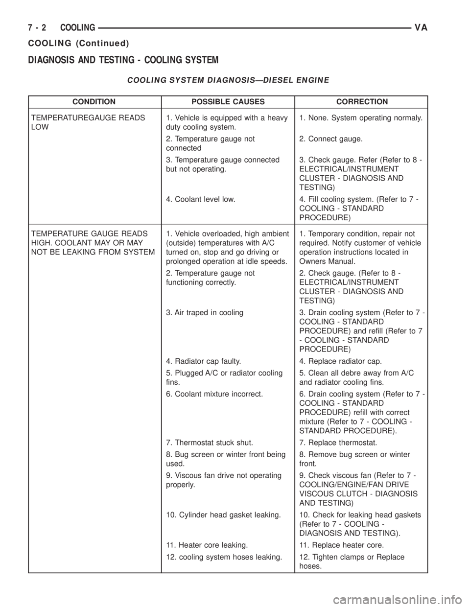
DIAGNOSIS AND TESTING - COOLING SYSTEM
COOLING SYSTEM DIAGNOSISÐDIESEL ENGINE
CONDITION POSSIBLE CAUSES CORRECTION
TEMPERATUREGAUGE READS
LOW1. Vehicle is equipped with a heavy
duty cooling system.1. None. System operating normaly.
2. Temperature gauge not
connected2. Connect gauge.
3. Temperature gauge connected
but not operating.3. Check gauge. Refer (Refer to 8 -
ELECTRICAL/INSTRUMENT
CLUSTER - DIAGNOSIS AND
TESTING)
4. Coolant level low. 4. Fill cooling system. (Refer to 7 -
COOLING - STANDARD
PROCEDURE)
TEMPERATURE GAUGE READS
HIGH. COOLANT MAY OR MAY
NOT BE LEAKING FROM SYSTEM1. Vehicle overloaded, high ambient
(outside) temperatures with A/C
turned on, stop and go driving or
prolonged operation at idle speeds.1. Temporary condition, repair not
required. Notify customer of vehicle
operation instructions located in
Owners Manual.
2. Temperature gauge not
functioning correctly.2. Check gauge. (Refer to 8 -
ELECTRICAL/INSTRUMENT
CLUSTER - DIAGNOSIS AND
TESTING)
3. Air traped in cooling 3. Drain cooling system (Refer to 7 -
COOLING - STANDARD
PROCEDURE) and refill (Refer to 7
- COOLING - STANDARD
PROCEDURE)
4. Radiator cap faulty. 4. Replace radiator cap.
5. Plugged A/C or radiator cooling
fins.5. Clean all debre away from A/C
and radiator cooling fins.
6. Coolant mixture incorrect. 6. Drain cooling system (Refer to 7 -
COOLING - STANDARD
PROCEDURE) refill with correct
mixture (Refer to 7 - COOLING -
STANDARD PROCEDURE).
7. Thermostat stuck shut. 7. Replace thermostat.
8. Bug screen or winter front being
used.8. Remove bug screen or winter
front.
9. Viscous fan drive not operating
properly.9. Check viscous fan (Refer to 7 -
COOLING/ENGINE/FAN DRIVE
VISCOUS CLUTCH - DIAGNOSIS
AND TESTING)
10. Cylinder head gasket leaking. 10. Check for leaking head gaskets
(Refer to 7 - COOLING -
DIAGNOSIS AND TESTING).
11. Heater core leaking. 11. Replace heater core.
12. cooling system hoses leaking. 12. Tighten clamps or Replace
hoses.
7 - 2 COOLINGVA
COOLING (Continued)
Page 99 of 1232
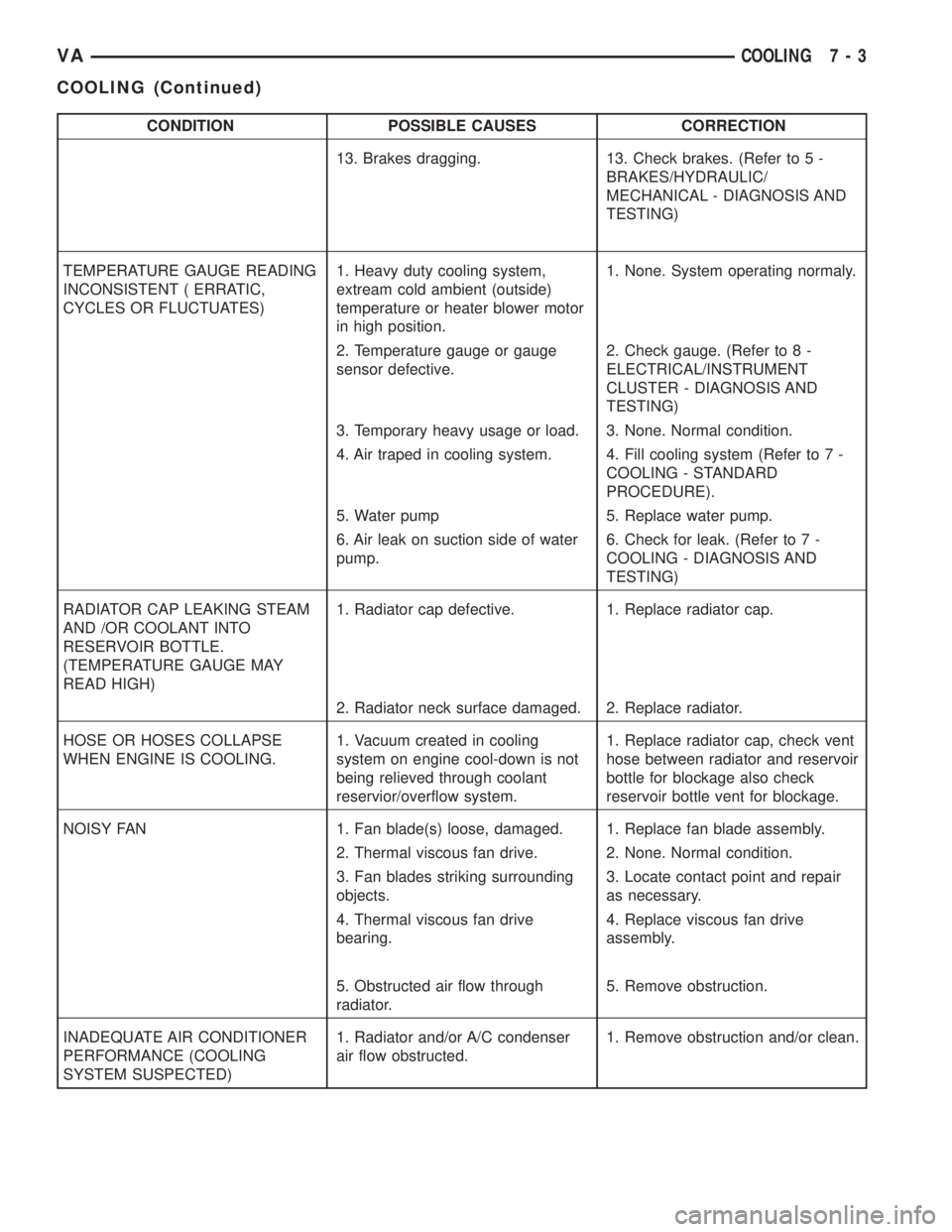
CONDITION POSSIBLE CAUSES CORRECTION
13. Brakes dragging. 13. Check brakes. (Refer to 5 -
BRAKES/HYDRAULIC/
MECHANICAL - DIAGNOSIS AND
TESTING)
TEMPERATURE GAUGE READING
INCONSISTENT ( ERRATIC,
CYCLES OR FLUCTUATES)1. Heavy duty cooling system,
extream cold ambient (outside)
temperature or heater blower motor
in high position.1. None. System operating normaly.
2. Temperature gauge or gauge
sensor defective.2. Check gauge. (Refer to 8 -
ELECTRICAL/INSTRUMENT
CLUSTER - DIAGNOSIS AND
TESTING)
3. Temporary heavy usage or load. 3. None. Normal condition.
4. Air traped in cooling system. 4. Fill cooling system (Refer to 7 -
COOLING - STANDARD
PROCEDURE).
5. Water pump 5. Replace water pump.
6. Air leak on suction side of water
pump.6. Check for leak. (Refer to 7 -
COOLING - DIAGNOSIS AND
TESTING)
RADIATOR CAP LEAKING STEAM
AND /OR COOLANT INTO
RESERVOIR BOTTLE.
(TEMPERATURE GAUGE MAY
READ HIGH)1. Radiator cap defective. 1. Replace radiator cap.
2. Radiator neck surface damaged. 2. Replace radiator.
HOSE OR HOSES COLLAPSE
WHEN ENGINE IS COOLING.1. Vacuum created in cooling
system on engine cool-down is not
being relieved through coolant
reservior/overflow system.1. Replace radiator cap, check vent
hose between radiator and reservoir
bottle for blockage also check
reservoir bottle vent for blockage.
NOISY FAN 1. Fan blade(s) loose, damaged. 1. Replace fan blade assembly.
2. Thermal viscous fan drive. 2. None. Normal condition.
3. Fan blades striking surrounding
objects.3. Locate contact point and repair
as necessary.
4. Thermal viscous fan drive
bearing.4. Replace viscous fan drive
assembly.
5. Obstructed air flow through
radiator.5. Remove obstruction.
INADEQUATE AIR CONDITIONER
PERFORMANCE (COOLING
SYSTEM SUSPECTED)1. Radiator and/or A/C condenser
air flow obstructed.1. Remove obstruction and/or clean.
VACOOLING 7 - 3
COOLING (Continued)
Page 100 of 1232
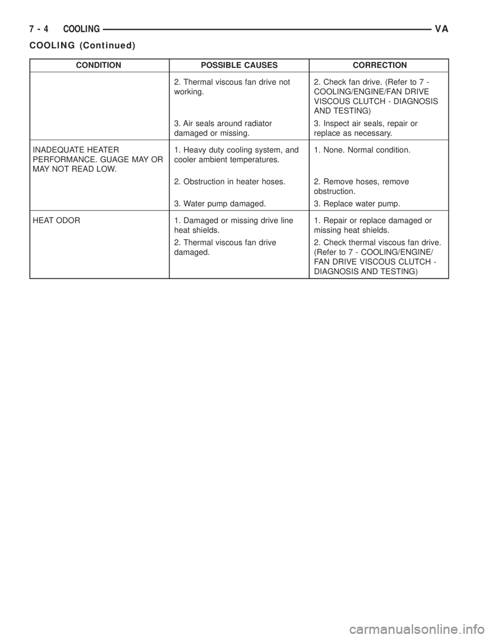
CONDITION POSSIBLE CAUSES CORRECTION
2. Thermal viscous fan drive not
working.2. Check fan drive. (Refer to 7 -
COOLING/ENGINE/FAN DRIVE
VISCOUS CLUTCH - DIAGNOSIS
AND TESTING)
3. Air seals around radiator
damaged or missing.3. Inspect air seals, repair or
replace as necessary.
INADEQUATE HEATER
PERFORMANCE. GUAGE MAY OR
MAY NOT READ LOW.1. Heavy duty cooling system, and
cooler ambient temperatures.1. None. Normal condition.
2. Obstruction in heater hoses. 2. Remove hoses, remove
obstruction.
3. Water pump damaged. 3. Replace water pump.
HEAT ODOR 1. Damaged or missing drive line
heat shields.1. Repair or replace damaged or
missing heat shields.
2. Thermal viscous fan drive
damaged.2. Check thermal viscous fan drive.
(Refer to 7 - COOLING/ENGINE/
FAN DRIVE VISCOUS CLUTCH -
DIAGNOSIS AND TESTING)
7 - 4 COOLINGVA
COOLING (Continued)
Page 105 of 1232
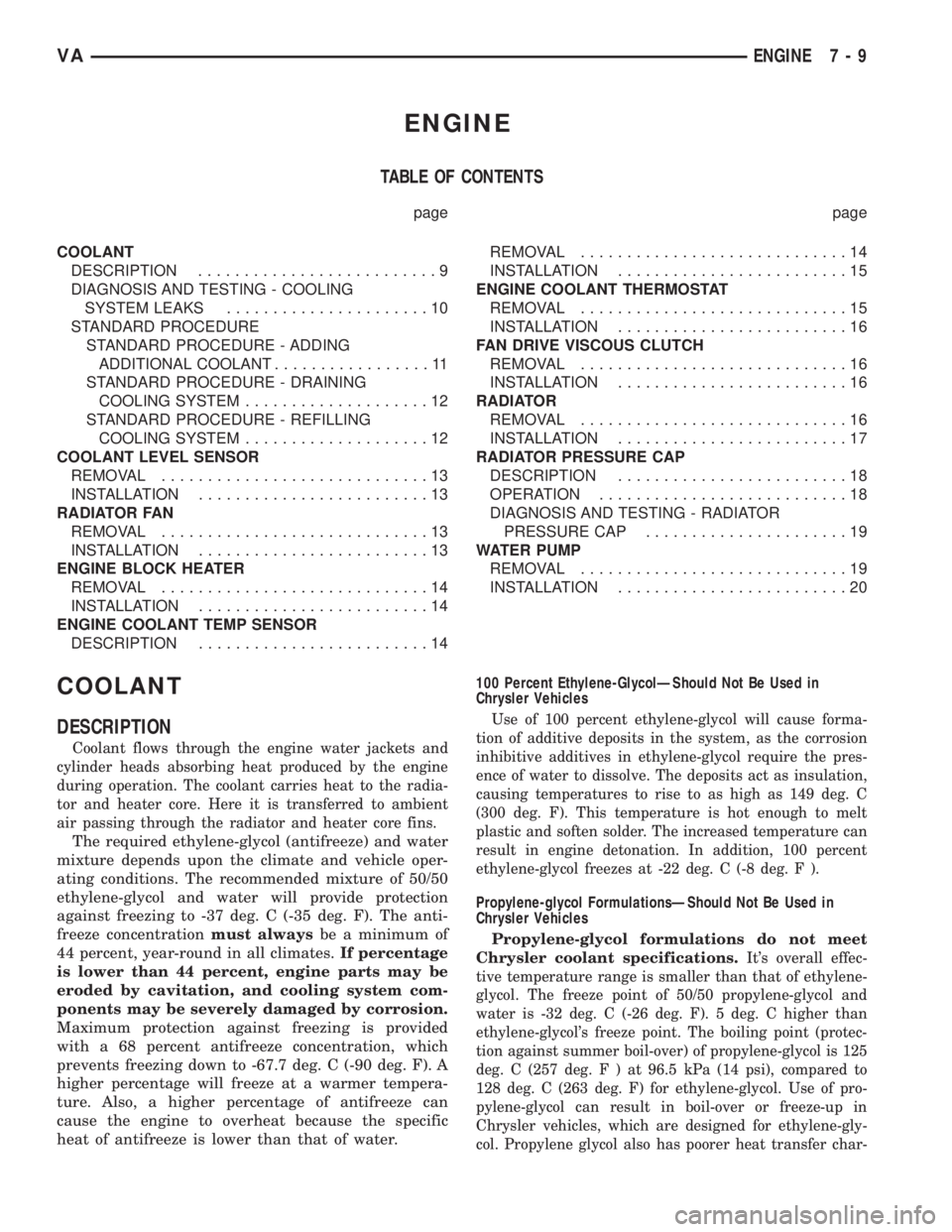
ENGINE
TABLE OF CONTENTS
page page
COOLANT
DESCRIPTION..........................9
DIAGNOSIS AND TESTING - COOLING
SYSTEM LEAKS......................10
STANDARD PROCEDURE
STANDARD PROCEDURE - ADDING
ADDITIONAL COOLANT.................11
STANDARD PROCEDURE - DRAINING
COOLING SYSTEM....................12
STANDARD PROCEDURE - REFILLING
COOLING SYSTEM....................12
COOLANT LEVEL SENSOR
REMOVAL.............................13
INSTALLATION.........................13
RADIATOR FAN
REMOVAL.............................13
INSTALLATION.........................13
ENGINE BLOCK HEATER
REMOVAL.............................14
INSTALLATION.........................14
ENGINE COOLANT TEMP SENSOR
DESCRIPTION.........................14REMOVAL.............................14
INSTALLATION.........................15
ENGINE COOLANT THERMOSTAT
REMOVAL.............................15
INSTALLATION.........................16
FAN DRIVE VISCOUS CLUTCH
REMOVAL.............................16
INSTALLATION.........................16
RADIATOR
REMOVAL.............................16
INSTALLATION.........................17
RADIATOR PRESSURE CAP
DESCRIPTION.........................18
OPERATION...........................18
DIAGNOSIS AND TESTING - RADIATOR
PRESSURE CAP......................19
WATER PUMP
REMOVAL.............................19
INSTALLATION.........................20
COOLANT
DESCRIPTION
Coolant flows through the engine water jackets and
cylinder heads absorbing heat produced by the engine
during operation. The coolant carries heat to the radia-
tor and heater core. Here it is transferred to ambient
air passing through the radiator and heater core fins.
The required ethylene-glycol (antifreeze) and water
mixture depends upon the climate and vehicle oper-
ating conditions. The recommended mixture of 50/50
ethylene-glycol and water will provide protection
against freezing to -37 deg. C (-35 deg. F). The anti-
freeze concentrationmust alwaysbe a minimum of
44 percent, year-round in all climates.If percentage
is lower than 44 percent, engine parts may be
eroded by cavitation, and cooling system com-
ponents may be severely damaged by corrosion.
Maximum protection against freezing is provided
with a 68 percent antifreeze concentration, which
prevents freezing down to -67.7 deg. C (-90 deg. F). A
higher percentage will freeze at a warmer tempera-
ture. Also, a higher percentage of antifreeze can
cause the engine to overheat because the specific
heat of antifreeze is lower than that of water.100 Percent Ethylene-GlycolÐShould Not Be Used in
Chrysler Vehicles
Use of 100 percent ethylene-glycol will cause forma-
tion of additive deposits in the system, as the corrosion
inhibitive additives in ethylene-glycol require the pres-
ence of water to dissolve. The deposits act as insulation,
causing temperatures to rise to as high as 149 deg. C
(300 deg. F). This temperature is hot enough to melt
plastic and soften solder. The increased temperature can
result in engine detonation. In addition, 100 percent
ethylene-glycol freezes at -22 deg. C (-8 deg. F ).
Propylene-glycol FormulationsÐShould Not Be Used in
Chrysler Vehicles
Propylene-glycol formulations do not meet
Chrysler coolant specifications.
It's overall effec-
tive temperature range is smaller than that of ethylene-
glycol. The freeze point of 50/50 propylene-glycol and
water is -32 deg. C (-26 deg. F). 5 deg. C higher than
ethylene-glycol's freeze point. The boiling point (protec-
tion against summer boil-over) of propylene-glycol is 125
deg. C (257 deg.F)at96.5 kPa (14 psi), compared to
128 deg. C (263 deg. F) for ethylene-glycol. Use of pro-
pylene-glycol can result in boil-over or freeze-up in
Chrysler vehicles, which are designed for ethylene-gly-
col. Propylene glycol also has poorer heat transfer char-
VAENGINE 7 - 9