2005 MERCEDES-BENZ SPRINTER turn signal
[x] Cancel search: turn signalPage 203 of 1232
system illuminates the selected right or left turn sig-
nal indicator and the turn signal lamps begin to
flash. The turn signal lamps include a bulb integral
to each front lamp unit and each tail lamp unit, as
well as a repeater lamp bulb located on each front
fender above the front wheels. When the turn signal
system is activated, the turn signal switch circuitry
within the multi-function switch and the electronic
circuitry of the wipers, turn signals and engine start
control module within the fuse block will repeatedly
energize and de-energize the turn signal relay
located in the fuse block. The turn signal relay
switches battery current from a fused ignition switch
output fuse in the fuse block to the appropriate turn
signal indicator and turn signal lamps.
The ElectroMechanical Instrument Cluster (EMIC)
contactless relay will generate repetitive, audible
turn signal ªclickº sounds to emulate the sounds of a
conventional electro-mechanical turn signal flasher
at one of two rates to coincide with the flashing of
the turn signals. The slow rate emulates normal turn
signal operation, while the fast rate emulates ªbulb
outº turn signal operation.
SPECIFICATIONS - LAMPS/LIGHTING -
EXTERIOR
BULB SPECIFICATIONS
LAMP BULB
Backup P21W - 12V 21W
Brake & Rear Park P21/5W - 12V 21/5W
Center High Mounted
StopP21W - 12V 21W
Clearance W3W - 12V 3W
Front Fog H1 - 12V 55W
Front Position W5W - 12V 5W
Front Turn, Park & Side
Marker3457 NA - 12V 28/7.5W
Amber Glass
Low Beam Headlamp H7 - 12V 55W
High Beam Headlamp H1 - 12V 55W
License Plate C5W - 12V 5W
Rear Side Marker R5W - 12V 5W
Rear Turn P21W - 12V 21W
Side Repeater W5W - 12V 3W
BACKUP LAMP BULB
REMOVAL
(1) Disconnect and isolate the battery negative
cable.(2) If the vehicle is so equipped, remove the trim
from the inside of the right or left rear corner pillar.
(3) From inside the vehicle, use hand pressure to
push the two latch tabs toward the center of the tail
lamp unit socket plate and pull the socket plate
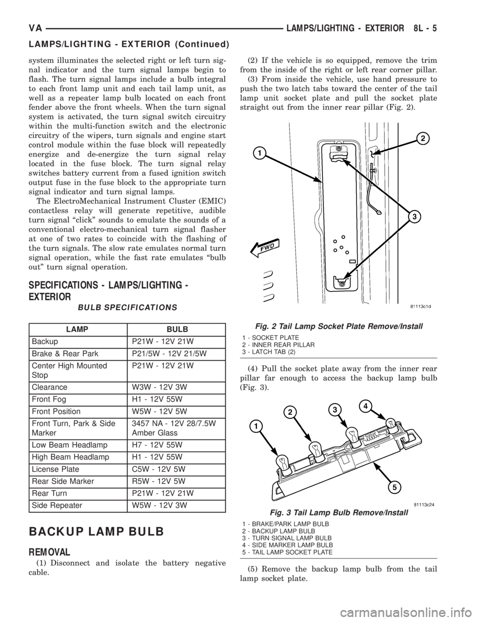
straight out from the inner rear pillar (Fig. 2).
(4) Pull the socket plate away from the inner rear
pillar far enough to access the backup lamp bulb
(Fig. 3).
(5) Remove the backup lamp bulb from the tail
lamp socket plate.
Fig. 2 Tail Lamp Socket Plate Remove/Install
1 - SOCKET PLATE
2 - INNER REAR PILLAR
3 - LATCH TAB (2)
Fig. 3 Tail Lamp Bulb Remove/Install
1 - BRAKE/PARK LAMP BULB
2 - BACKUP LAMP BULB
3 - TURN SIGNAL LAMP BULB
4 - SIDE MARKER LAMP BULB
5 - TAIL LAMP SOCKET PLATE
VALAMPS/LIGHTING - EXTERIOR 8L - 5
LAMPS/LIGHTING - EXTERIOR (Continued)
Page 205 of 1232
BRAKE/PARK LAMP BULB
REMOVAL
(1) Disconnect and isolate the battery negative
cable.
(2) If the vehicle is so equipped, remove the trim
from the inside of the right or left rear corner pillar.
(3) From inside the vehicle, use hand pressure to
push the two latch tabs toward the center of the tail
lamp unit socket plate and pull the socket plate
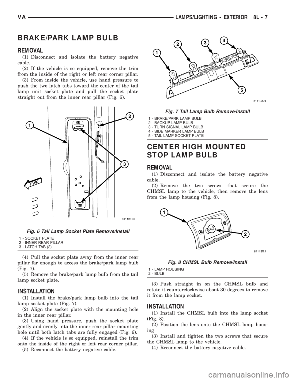
straight out from the inner rear pillar (Fig. 6).
(4) Pull the socket plate away from the inner rear
pillar far enough to access the brake/park lamp bulb
(Fig. 7).
(5) Remove the brake/park lamp bulb from the tail
lamp socket plate.
INSTALLATION
(1) Install the brake/park lamp bulb into the tail
lamp socket plate (Fig. 7).
(2) Align the socket plate with the mounting hole
in the inner rear pillar.
(3) Using hand pressure, push the socket plate
gently and evenly into the inner rear pillar mounting
hole until both latch tabs are fully engaged (Fig. 6).
(4) If the vehicle is so equipped, reinstall the trim
onto the inside of the right or left rear corner pillar.
(5) Reconnect the battery negative cable.
CENTER HIGH MOUNTED
STOP LAMP BULB
REMOVAL
(1) Disconnect and isolate the battery negative
cable.
(2) Remove the two screws that secure the
CHMSL lamp to the vehicle, then remove the lens
from the lamp housing (Fig. 8).
(3) Push straight in on the CHMSL bulb and
rotate it counterclockwise about 30 degrees to remove
it from the lamp socket.
INSTALLATION
(1) Install the CHMSL bulb into the lamp socket
(Fig. 8).
(2) Position the lens onto the CHMSL lamp hous-
ing
(3) Install and tighten the two screws that secure
the CHMSL lamp to the vehicle.
(4) Reconnect the battery negative cable.
Fig. 6 Tail Lamp Socket Plate Remove/Install
1 - SOCKET PLATE
2 - INNER REAR PILLAR
3 - LATCH TAB (2)
Fig. 7 Tail Lamp Bulb Remove/Install
1 - BRAKE/PARK LAMP BULB
2 - BACKUP LAMP BULB
3 - TURN SIGNAL LAMP BULB
4 - SIDE MARKER LAMP BULB
5 - TAIL LAMP SOCKET PLATE
Fig. 8 CHMSL Bulb Remove/Install
1 - LAMP HOUSING
2 - BULB
VALAMPS/LIGHTING - EXTERIOR 8L - 7
Page 219 of 1232
REAR SIDE MARKER LAMP
BULB
REMOVAL
(1) Disconnect and isolate the battery negative
cable.
(2) If the vehicle is so equipped, remove the trim
from the inside of the right or left rear corner pillar.
(3) From inside the vehicle, use hand pressure to
push the two latch tabs toward the center of the tail
lamp unit socket plate and pull the socket plate
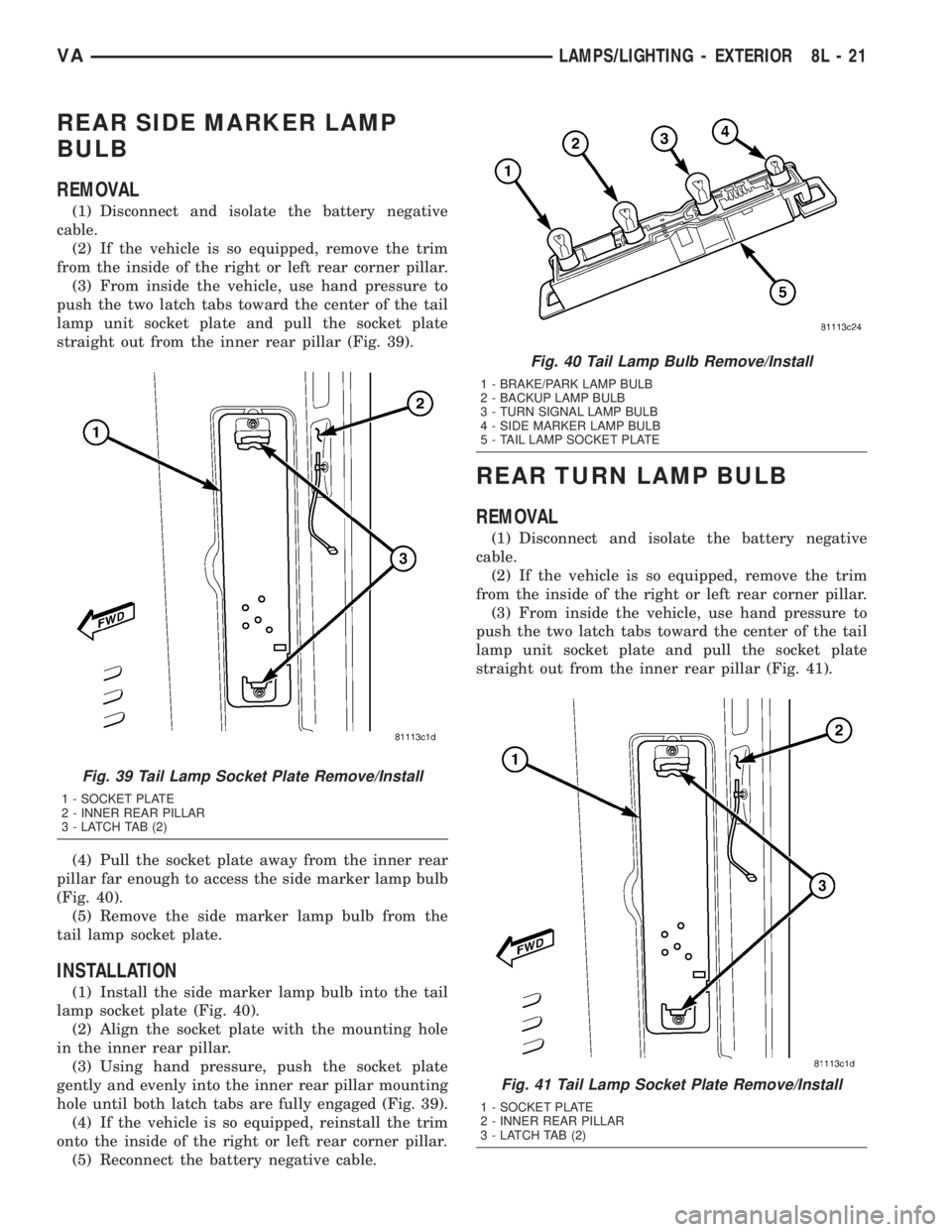
straight out from the inner rear pillar (Fig. 39).
(4) Pull the socket plate away from the inner rear
pillar far enough to access the side marker lamp bulb
(Fig. 40).
(5) Remove the side marker lamp bulb from the
tail lamp socket plate.
INSTALLATION
(1) Install the side marker lamp bulb into the tail
lamp socket plate (Fig. 40).
(2) Align the socket plate with the mounting hole
in the inner rear pillar.
(3) Using hand pressure, push the socket plate
gently and evenly into the inner rear pillar mounting
hole until both latch tabs are fully engaged (Fig. 39).
(4) If the vehicle is so equipped, reinstall the trim
onto the inside of the right or left rear corner pillar.
(5) Reconnect the battery negative cable.
REAR TURN LAMP BULB
REMOVAL
(1) Disconnect and isolate the battery negative
cable.
(2) If the vehicle is so equipped, remove the trim
from the inside of the right or left rear corner pillar.
(3) From inside the vehicle, use hand pressure to
push the two latch tabs toward the center of the tail
lamp unit socket plate and pull the socket plate
straight out from the inner rear pillar (Fig. 41).
Fig. 39 Tail Lamp Socket Plate Remove/Install
1 - SOCKET PLATE
2 - INNER REAR PILLAR
3 - LATCH TAB (2)
Fig. 40 Tail Lamp Bulb Remove/Install
1 - BRAKE/PARK LAMP BULB
2 - BACKUP LAMP BULB
3 - TURN SIGNAL LAMP BULB
4 - SIDE MARKER LAMP BULB
5 - TAIL LAMP SOCKET PLATE
Fig. 41 Tail Lamp Socket Plate Remove/Install
1 - SOCKET PLATE
2 - INNER REAR PILLAR
3 - LATCH TAB (2)
VALAMPS/LIGHTING - EXTERIOR 8L - 21
Page 220 of 1232
(4) Pull the socket plate away from the inner rear
pillar far enough to access the turn signal lamp bulb
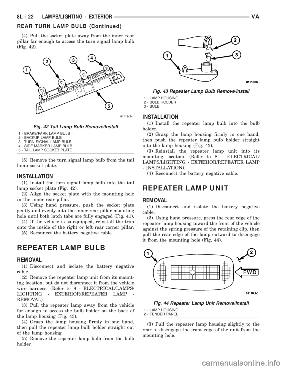
(Fig. 42).
(5) Remove the turn signal lamp bulb from the tail
lamp socket plate.
INSTALLATION
(1) Install the turn signal lamp bulb into the tail
lamp socket plate (Fig. 42).
(2) Align the socket plate with the mounting hole
in the inner rear pillar.
(3) Using hand pressure, push the socket plate
gently and evenly into the inner rear pillar mounting
hole until both latch tabs are fully engaged (Fig. 41).
(4) If the vehicle is so equipped, reinstall the trim
onto the inside of the right or left rear corner pillar.
(5) Reconnect the battery negative cable.
REPEATER LAMP BULB
REMOVAL
(1) Disconnect and isolate the battery negative
cable.
(2) Remove the repeater lamp unit from its mount-
ing location, but do not disconnect it from the vehicle
wire harness. (Refer to 8 - ELECTRICAL/LAMPS/
LIGHTING - EXTERIOR/REPEATER LAMP -
REMOVAL).
(3) Pull the repeater lamp away from the vehicle
far enough to access the bulb holder on the back of
the lamp housing (Fig. 43).
(4) Grasp the lamp housing firmly in one hand,
then pull the repeater lamp bulb holder straight out
of the lamp housing.
(5) Remove the repeater lamp bulb from the bulb
holder.
INSTALLATION
(1) Install the repeater lamp bulb into the bulb
holder.
(2) Grasp the lamp housing firmly in one hand,
then push the repeater lamp bulb holder straight
into the lamp housing (Fig. 43).
(3) Reinstall the repeater lamp unit into its
mounting location. (Refer to 8 - ELECTRICAL/
LAMPS/LIGHTING - EXTERIOR/REPEATER LAMP
- INSTALLATION).
(4) Reconnect the battery negative cable.
REPEATER LAMP UNIT
REMOVAL
(1) Disconnect and isolate the battery negative
cable.
(2) Using hand pressure, press the rear edge of the
repeater lamp housing toward the front of the vehicle
against the spring pressure of the retaining clip, then
pull the rear edge of the lamp outward to disengage
it from the mounting hole (Fig. 44).
(3) Pull the repeater lamp housing slightly to the
rear to disengage the front edge of the unit from the
mounting hole.
Fig. 42 Tail Lamp Bulb Remove/Install
1 - BRAKE/PARK LAMP BULB
2 - BACKUP LAMP BULB
3 - TURN SIGNAL LAMP BULB
4 - SIDE MARKER LAMP BULB
5 - TAIL LAMP SOCKET PLATE
Fig. 43 Repeater Lamp Bulb Remove/Install
1 - LAMP HOUSING
2 - BULB HOLDER
3 - BULB
Fig. 44 Repeater Lamp Unit Remove/Install
1 - LAMP HOUSING
2 - FENDER PANEL
8L - 22 LAMPS/LIGHTING - EXTERIORVA
REAR TURN LAMP BULB (Continued)
Page 222 of 1232
TURN SIGNAL RELAY
REMOVAL
WARNING: ON VEHICLES EQUIPPED WITH AIRBAGS,
DISABLE THE SUPPLEMENTAL RESTRAINT SYSTEM
BEFORE ATTEMPTING ANY STEERING WHEEL,
STEERING COLUMN, DRIVER AIRBAG, PASSENGER
AIRBAG, SEAT BELT TENSIONER, OR INSTRUMENT
PANEL COMPONENT DIAGNOSIS OR SERVICE. DIS-
CONNECT AND ISOLATE THE BATTERY NEGATIVE
(GROUND) CABLE, THEN WAIT TWO MINUTES FOR
THE SYSTEM CAPACITOR TO DISCHARGE BEFORE
PERFORMING FURTHER DIAGNOSIS OR SERVICE.
THIS IS THE ONLY SURE WAY TO DISABLE THE SUP-
PLEMENTAL RESTRAINT SYSTEM. FAILURE TO TAKE
THE PROPER PRECAUTIONS COULD RESULT IN
ACCIDENTAL AIRBAG DEPLOYMENT AND POSSIBLE
PERSONAL INJURY.
(1) Disconnect and isolate the battery negative
cable.
(2) Remove the fuse access panel from the steering
column opening cover below the steering column on
the instrument panel.
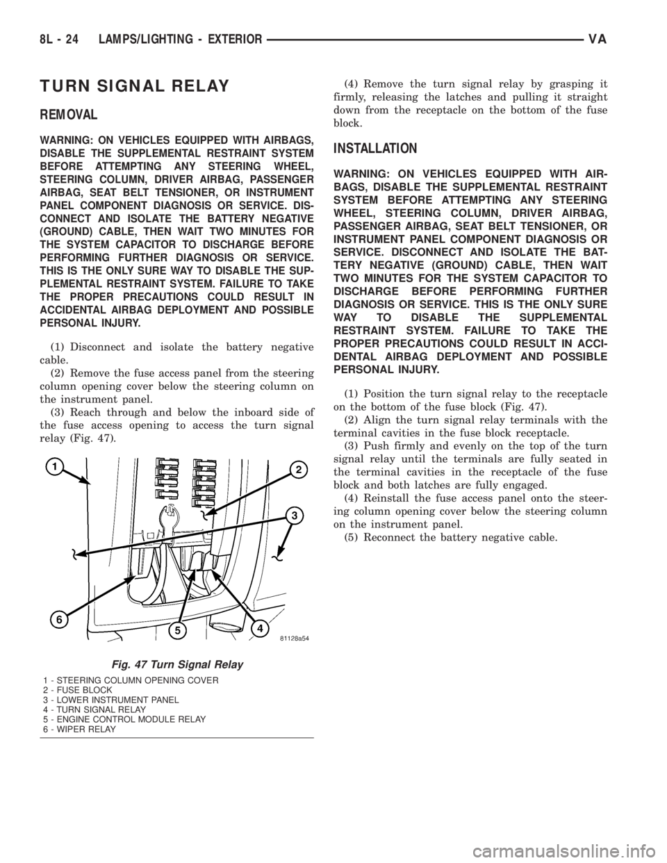
(3) Reach through and below the inboard side of
the fuse access opening to access the turn signal
relay (Fig. 47).(4) Remove the turn signal relay by grasping it
firmly, releasing the latches and pulling it straight
down from the receptacle on the bottom of the fuse
block.
INSTALLATION
WARNING: ON VEHICLES EQUIPPED WITH AIR-
BAGS, DISABLE THE SUPPLEMENTAL RESTRAINT
SYSTEM BEFORE ATTEMPTING ANY STEERING
WHEEL, STEERING COLUMN, DRIVER AIRBAG,
PASSENGER AIRBAG, SEAT BELT TENSIONER, OR
INSTRUMENT PANEL COMPONENT DIAGNOSIS OR
SERVICE. DISCONNECT AND ISOLATE THE BAT-
TERY NEGATIVE (GROUND) CABLE, THEN WAIT
TWO MINUTES FOR THE SYSTEM CAPACITOR TO
DISCHARGE BEFORE PERFORMING FURTHER
DIAGNOSIS OR SERVICE. THIS IS THE ONLY SURE
WAY TO DISABLE THE SUPPLEMENTAL
RESTRAINT SYSTEM. FAILURE TO TAKE THE
PROPER PRECAUTIONS COULD RESULT IN ACCI-
DENTAL AIRBAG DEPLOYMENT AND POSSIBLE
PERSONAL INJURY.
(1) Position the turn signal relay to the receptacle
on the bottom of the fuse block (Fig. 47).
(2) Align the turn signal relay terminals with the
terminal cavities in the fuse block receptacle.
(3) Push firmly and evenly on the top of the turn
signal relay until the terminals are fully seated in
the terminal cavities in the receptacle of the fuse
block and both latches are fully engaged.
(4) Reinstall the fuse access panel onto the steer-
ing column opening cover below the steering column
on the instrument panel.
(5) Reconnect the battery negative cable.
Fig. 47 Turn Signal Relay
1 - STEERING COLUMN OPENING COVER
2 - FUSE BLOCK
3 - LOWER INSTRUMENT PANEL
4 - TURN SIGNAL RELAY
5 - ENGINE CONTROL MODULE RELAY
6 - WIPER RELAY
8L - 24 LAMPS/LIGHTING - EXTERIORVA
Page 242 of 1232
splices, splice block connectors, and many different
types of wire harness terminal connectors and insu-
lators. Refer to the appropriate wiring information.
The wiring information includes wiring diagrams,
proper wire and connector repair procedures, further
details on wire harness routing and retention, as well
as pin-out and location views for the various wire
harness connectors, splices and grounds.
OPERATION
ACTIVE RESTRAINTS
The primary passenger restraints in this or any
other vehicle are the standard equipment factory-in-
stalled seat belts. Seat belts are referred to as an
active restraint because the vehicle occupants are
required to physically fasten and properly adjust
these restraints in order to benefit from them. See
the owner's manual in the vehicle glove box for more
information on the features, use and operation of all
of the factory-installed active restraints.
PASSIVE RESTRAINTS
The passive restraints are referred to as a supple-
mental restraint system because they were designed
and are intended to enhance the protection for the
occupants of the vehicleonlywhen used in conjunc-
tion with the seat belts. They are referred to as pas-
sive restraints because the vehicle occupants are not
required to do anything to make them operate; how-
ever, the vehicle occupants must be wearing their
seat belts in order to obtain the maximum safety
benefit from the factory-installed supplemental
restraint system.
The supplemental restraint system electrical cir-
cuits are continuously monitored and controlled by a
microprocessor and software contained within the
Airbag Control Module (ACM). An airbag indicator in
the ElectroMechanical Instrument Cluster (EMIC)
illuminates for about four seconds as a bulb test each
time the ignition switch is turned to the On or Start
positions. Following the bulb test, the airbag indica-
tor is turned on or off by the ACM to indicate the
status of the supplemental restraint system. If the
airbag indicator comes on either solid or flashing at
any time other than during the bulb test, it indicates
that there is a problem in the supplemental restraint
system electrical circuits. Such a problem may cause
airbags not to deploy when required, or to deploy
when not required.
Deployment of the supplemental restraints
depends upon the angle and severity of an impact.Deployment is not based upon vehicle speed; rather,
deployment is based upon the rate of deceleration as
measured by the forces of gravity (G force) upon the
impact sensor. When an impact is severe enough, the
microprocessor in the ACM signals the inflator of the
appropriate airbag units to deploy their airbag cush-
ions. The front seat belt tensioners are provided with
a deployment signal by the ACM in conjunction with
the driver and passenger airbags. During a frontal
vehicle impact, the knee blockers work in concert
with properly fastened and adjusted seat belts to
restrain both the driver and the front seat passenger
in the proper position for an airbag deployment. The
knee blockers also absorb and distribute the crash
energy from the driver and the front seat passenger
to the structure of the instrument panel. The seat
belt tensioners remove the slack from the front seat
belts to provide further assurance that the driver and
front seat passenger are properly positioned and
restrained for an airbag deployment.
Typically, the vehicle occupants recall more about
the events preceding and following a collision than
they do of an airbag deployment itself. This is
because the airbag deployment and deflation occur so
rapidly. In a typical 48 kilometer-per-hour (30 mile-
per-hour) barrier impact, from the moment of impact
until the airbags are fully inflated takes only a few
milliseconds. Within one to two seconds from the
moment of impact, the airbags are almost entirely
deflated. The times cited for these events are approx-
imations, which apply only to a barrier impact at the
given speed. Actual times will vary somewhat,
depending upon the vehicle speed, impact angle,
severity of the impact, and the type of collision.
When the ACM monitors a problem in any of the
front airbag system circuits or components, including
the seat belt tensioners, it stores a fault code or
Diagnostic Trouble Code (DTC) in its memory circuit
and sends a hard wired output to the EMIC to turn
on the airbag indicator. If the EMIC detects a prob-
lem in the airbag indicator or airbag indicator circuit,
the cluster will flash the seatbelt indicator on and
off. Proper testing of the supplemental restraint sys-
tem components as well as the retrieval or erasure of
a DTC from the ACM requires the use of a DRBIIIt
scan tool. Refer to the appropriate diagnostic infor-
mation.
See the owner's manual in the vehicle glove box for
more information on the features, use and operation
of all of the factory-installed passive restraints.
8O - 4 RESTRAINTSVA
RESTRAINTS (Continued)
Page 244 of 1232
WARNING: ON VEHICLES EQUIPPED WITH AIR-
BAGS, DISABLE THE SUPPLEMENTAL RESTRAINT
SYSTEM BEFORE ATTEMPTING ANY STEERING
WHEEL, STEERING COLUMN, DRIVER AIRBAG,
PASSENGER AIRBAG, SEAT BELT TENSIONER, OR
INSTRUMENT PANEL COMPONENT DIAGNOSIS OR
SERVICE. DISCONNECT AND ISOLATE THE BAT-
TERY NEGATIVE (GROUND) CABLE, THEN WAIT
TWO MINUTES FOR THE SYSTEM CAPACITOR TO
DISCHARGE BEFORE PERFORMING FURTHER
DIAGNOSIS OR SERVICE. THIS IS THE ONLY SURE
WAY TO DISABLE THE SUPPLEMENTAL
RESTRAINT SYSTEM. FAILURE TO TAKE THE
PROPER PRECAUTIONS COULD RESULT IN ACCI-
DENTAL AIRBAG DEPLOYMENT AND POSSIBLE
PERSONAL INJURY.
STANDARD PROCEDURE
STANDARD PROCEDURE - HANDLING
NON-DEPLOYED SUPPLEMENTAL RESTRAINTS
At no time should any source of electricity be per-
mitted near the inflator on the back of a non-de-
ployed airbag or seat belt tensioner. When carrying a
non-deployed airbag, the trim cover or airbag cushion
side of the unit should be pointed away from the
body to minimize injury in the event of an accidental
deployment. If the airbag unit is placed on a bench or
any other surface, the trim cover or airbag cushion
side of the unit should be face up to minimize move-
ment in the event of an accidental deployment. When
handling a non-deployed seat belt tensioner, take
proper care to keep fingers out from under the
retractor cover and away from the seat belt webbing
where it exits from the retractor cover. In addition,
the supplemental restraint system should be dis-
armed whenever any steering wheel, steering col-
umn, seat belt tensioner, driver airbag, passenger
airbag, or instrument panel components require diag-
nosis or service. Failure to observe this warning
could result in accidental deployment and possible
personal injury.
All damaged, faulty or non-deployed airbags and
seat belt tensioners which are replaced on vehicles
are to be handled and disposed of properly. If an air-
bag or seat belt tensioner unit is faulty or damaged
and non-deployed, refer to the Hazardous Substance
Control System for proper disposal. Dispose of all
non-deployed and deployed airbags and seat belt ten-
sioners in a manner consistent with state, provincial,
local and federal regulations.
SUPPLEMENTAL RESTRAINT STORAGE
Airbags and seat belt tensioners must be stored in
their original, special container until they are used
for service. Also, they must be stored in a clean, dry
environment; away from sources of extreme heat,
sparks, and high electrical energy. Always place or
store any airbag on a surface with its trim cover or
airbag cushion side facing up, to minimize movement
in case of an accidental deployment.
STANDARD PROCEDURE - SERVICE AFTER A
SUPPLEMENTAL RESTRAINT DEPLOYMENT
Any vehicle which is to be returned to use follow-
ing a supplemental restraint deployment, must have
the deployed restraints replaced. In addition, if the
driver airbag has been deployed, the clockspring and
the steering wheel must be replaced. The seat belt
tensioners are deployed by the same signal that
deploys the driver and passenger airbags and must
also be replaced if either airbag has been deployed.
These components are not intended for reuse and
will be damaged or weakened as a result of a supple-
mental restraint deployment, which may or may not
be obvious during a visual inspection.
It is also critical that the mounting surfaces and/or
mounting brackets for the Airbag Control Module
(ACM) be closely inspected and restored to their orig-
inal conditions following any vehicle impact damage.
Because the ACM contains the impact sensor that is
used by the supplemental restraint system to moni-
tor or confirm the direction and severity of a vehicle
impact, improper orientation or insecure fastening of
this component may cause airbags not to deploy
when required, or to deploy when not required. All
other vehicle components should be closely inspected
following any supplemental restraint deployment, but
are to be replaced only as required by the extent of
the visible damage incurred.
CLEANUP PROCEDURE
Following a supplemental restraint deployment,
the vehicle interior will contain a powdery residue.
This residue consists primarily of harmless particu-
late by-products of the small pyrotechnic charge that
initiates the propellant used to deploy a supplemen-
tal restraint. However, this residue may also contain
traces of sodium hydroxide powder, a chemical
by-product of the propellant material that is used to
generate the inert gas that inflates the airbag. Since
sodium hydroxide powder can irritate the skin, eyes,
nose, or throat, be certain to wear safety glasses,
rubber gloves, and a long-sleeved shirt during
cleanup (Fig. 3).
8O - 6 RESTRAINTSVA
RESTRAINTS (Continued)
Page 247 of 1232
an electronic impact sensor, and an energy storage
capacitor. The ACM housing has three integral
mounting tabs. A stamped metal cover plate is per-
manently secured to the bottom of the ACM housing
to enclose and protect the internal electronic circuitry
and components. An arrow printed on a label on the
top of the ACM housing near the rear provides a
visual verification of the proper orientation of the
unit, and should always be pointed toward the front
of the vehicle. A molded plastic electrical connector
receptacle containing numerous terminal pins is inte-
gral to the left facing side of the ACM housing. These
terminal pins connect the ACM to the vehicle electri-
cal system through a dedicated take out and connec-
tor of the vehicle wire harness.
The impact sensor internal to the ACM is cali-
brated for the specific vehicle, and is only serviced as
a unit with the ACM. The ACM cannot be repaired or
adjusted and, if damaged or faulty, it must be
replaced.
OPERATION
The microprocessor in the Airbag Control Module
(ACM) contains the supplemental restraint system
logic circuits and controls all of the supplemental
restraint system components. The ACM uses
On-Board Diagnostics (OBD) and can communicate
with the DRBIIItscan tool using a diagnostic Serial
Communication Interface (SCI) data bus line for sup-
plemental restraint system programming or diagno-
sis and testing through the 16-way Data Link
Connector (DLC) located on the dash panel below the
driver side end of the instrument panel. A hard wired
output from the ACM is used for control of the airbag
indicator in the ElectroMechanical Instrument Clus-
ter (EMIC). (Refer to 8 - ELECTRICAL/INSTRU-
MENT CLUSTER/AIRBAG INDICATOR -
OPERATION).
The ACM microprocessor continuously monitors all
of the supplemental restraint system electrical cir-
cuits to determine the system readiness. If the ACM
detects a monitored system fault, it sets an appropri-
ate Diagnostic Trouble Code (DTC) and sends an out-
put to the EMIC to turn on the airbag indicator. The
ACM illuminates the indicator for about four seconds
each time the ignition switch is turned to the On
position as a bulb test. If the indicator remains illu-
minated for about ten seconds after the ignition
switch is turned to the On position, the ACM has
detected a non-critical fault that poses no danger to
the vehicle occupants. If the airbag indicator illumi-
nates solid (not flashing) while driving or stays on
longer than ten seconds following the bulb test, the
ACM has detected a critical fault that may cause the
airbags not to deploy when required or to deploy
when not required. An active fault only remains forthe duration of the fault, or in some cases, for the
duration of the current ignition switch cycle, while a
stored fault causes a DTC to be stored in memory by
the ACM.
The ACM receives battery current through a fused
ignition switch output circuit. The ACM receives
ground through a ground circuit and take out of the
vehicle wire harness. This take out has an eyelet ter-
minal connector secured by a nut to a ground stud on
the floor panel directly below the ACM within the
driver side seat riser. A case ground is also provided
for the ACM through a ground circuit and eyelet ter-
minal connector secured under the left rear ACM
mounting screw. These connections allow the ACM to
be operational whenever the ignition switch is in the
On position. The ACM also contains an energy-stor-
age capacitor. When the ignition switch is in the On
position, this capacitor is continually being charged
with enough electrical energy to deploy the supple-
mental restraint components for up to one second fol-
lowing a battery disconnect or failure. The purpose of
the capacitor is to provide backup supplemental
restraint system protection in case there is a loss of
battery current supply to the ACM during an impact.
An electronic impact sensor is contained within the
ACM. The electronic impact sensor is an accelerome-
ter that senses the rate of vehicle deceleration, which
provides verification of the direction and severity of
an impact. A pre-programmed decision algorithm in
the ACM microprocessor determines when the decel-
eration rate as signaled by the impact sensor indi-
cates an impact that is severe enough to require
supplemental restraint system protection. When the
programmed conditions are met, the ACM sends the
proper electrical signals to deploy the seat belt ten-
sioners and front airbags.
The ACM also provides a hard wired electrical
crash signal output following a supplemental
restraint deployment event. This output is used to
signal other electronic modules in the vehicle to pro-
vide their enhanced accident response features,
which include automatically disabling the engine
from running and unlocking all of the doors. How-
ever, these responses are each dependent upon the
circuits, components, and modules controlling these
features remaining intact from collateral damage
incurred during the vehicle impact.
A single ACM is used for all variations of the sup-
plemental restraint system available in this vehicle.
This ACM is programmable and in order to function
properly it must be programmed for the correct vehi-
cle supplemental restraint system equipment using
an initialization procedure. The initialization proce-
dure requires the use of a DRBIIItscan tool. Refer to
the appropriate diagnostic information. The hard
wired inputs and outputs for the ACM may be diag-
VARESTRAINTS 8O - 9
AIRBAG CONTROL MODULE (Continued)