2005 MERCEDES-BENZ SPRINTER turn signal
[x] Cancel search: turn signalPage 251 of 1232
vide access to the case mounting screws. The lower
side of the rotor hub also serves as an integral
molded plastic turn signal cancel cam.
A single connector receptacle on the upper surface
of the rotor has pigtail wires that connect to the horn
switch and the driver airbag on the steering wheel,
while a single connector receptacle on the lower sur-
face of the case has pigtail wires that connect the
clockspring to the vehicle wire harness on the steer-
ing column. Within the plastic case and wound
around the rotor spool is a long ribbon-like tape that
consists of several thin copper wire leads sandwiched
between two thin plastic membranes. The outer end
of the tape terminates at the connector receptacle
that faces the steering column, while the inner end of
the tape terminates at the connector receptacle on
the hub of the clockspring rotor that faces the steer-
ing wheel.
Service replacement clocksprings are shipped pre-
centered and with the mounting screws backed out
from the case far enough to engage the access holes
in the upper surface of the rotor. The mounting
screws secure the centered clockspring rotor to the
clockspring case during shipment, but allow free
rotation of the rotor once the clockspring is properly
installed on the steering column. (Refer to 8 - ELEC-
TRICAL/RESTRAINTS/CLOCKSPRING - STAN-
DARD PROCEDURE - CLOCKSPRING
CENTERING).
The clockspring cannot be repaired. If the clock-
spring is faulty, damaged, or if the driver airbag has
been deployed, the clockspring must be replaced.
OPERATION
The clockspring is a mechanical electrical circuit
component that is used to provide continuous electri-
cal continuity between the fixed vehicle wire harness
and the electrical components mounted on or in the
rotating steering wheel. On this model the rotating
electrical components include the driver airbag and
the horn switch. The clockspring case is positioned
and secured to the multi-function switch housing
near the top of the steering column. The connector
receptacle on the underside of the fixed clockspring
case connects the clockspring to the vehicle electrical
system through two take outs with connectors from
the vehicle wire harness.
The clockspring rotor is movable and is keyed by
integral molded ribs on the inner circumference of
the rotor hub to the splines on the external circum-
ference of the upper steering column shaft. The two
integral lobes of the turn signal cancel cam formation
on the lower surface of the clockspring rotor hub con-
tact the turn signal cancel actuator of the multi-func-
tion switch to provide automatic turn signal
cancellation. The yellow sleeved pigtail wire on theupper surface of the clockspring rotor connects the
clockspring to the driver airbag, while two single pig-
tail wires connect to the feed and ground terminals of
the horn switch located within the hub cavity of the
steering wheel.
Like the clockspring in a timepiece, the clockspring
tape has travel limits and can be damaged by being
wound too tightly during full stop-to-stop steering
wheel rotation. To prevent this from occurring, the
clockspring is centered when it is installed on the
steering column. Centering the clockspring indexes
the clockspring tape to the movable steering compo-
nents so that the tape can operate within its
designed travel limits. However, if the clockspring is
removed from the steering column or if the steering
shaft is disconnected from the steering gear, the
clockspring spool can change position relative to the
movable steering components. The clockspring must
be re-centered following completion of this service or
the tape may be damaged.
Service replacement clocksprings are shipped pre-
centered and with the mounting screws backed out
from the case far enough to engage the access holes
in the upper surface of the rotor. The mounting
screws secure the centered clockspring rotor to the
clockspring case during shipment, but allow free
rotation of the rotor once the clockspring is properly
installed on the steering column. The clockspring
mounting screws should not be tightened into the
clockspring case until the clockspring has been
installed on the steering column. If the screws are
tightened into or removed from the case before the
clockspring is installed on a steering column, the
clockspring centering procedure must be performed.
(Refer to 8 - ELECTRICAL/RESTRAINTS/CLOCK-
SPRING - STANDARD PROCEDURE - CLOCK-
SPRING CENTERING).
STANDARD PROCEDURE - CLOCKSPRING
CENTERING
The clockspring is designed to wind and unwind
when the steering wheel is rotated, but is only
designed to rotate the same number of turns (about
six to seven complete rotations) as the steering wheel
can be turned from stop to stop. Centering the clock-
spring indexes the clockspring tape to other steering
components so that it can operate within its designed
travel limits. The rotor of a centered clockspring can
be rotated three to three and one-half turns in either
direction from the centered position, without damag-
ing the clockspring tape.
However, if the clockspring is removed for service
or if the steering column is disconnected from the
steering gear, the clockspring tape can change posi-
tion relative to the other steering components. The
clockspring must then be re-centered following com-
VARESTRAINTS 8O - 13
CLOCKSPRING (Continued)
Page 255 of 1232
OPERATION
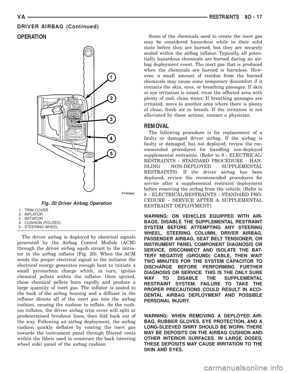
The driver airbag is deployed by electrical signals
generated by the Airbag Control Module (ACM)
through the driver airbag squib circuit to the initia-
tor in the airbag inflator (Fig. 20). When the ACM
sends the proper electrical signal to the initiator the
electrical energy generates enough heat to initiate a
small pyrotechnic charge which, in turn, ignites
chemical pellets within the inflator. Once ignited,
these chemical pellets burn rapidly and produce a
large quantity of inert gas. The inflator is sealed to
the back of the airbag housing and a diffuser in the
inflator directs all of the inert gas into the airbag
cushion, causing the cushion to inflate. As the cush-
ion inflates, the driver airbag trim cover will split at
predetermined breakout lines, then fold back out of
the way. Following an airbag deployment, the airbag
cushion quickly deflates by venting the inert gas
towards the instrument panel through filtered vents
within the fabric used to construct the back (steering
wheel side) panel of the airbag cushion.Some of the chemicals used to create the inert gas
may be considered hazardous while in their solid
state before they are burned, but they are securely
sealed within the airbag inflator. Typically, all poten-
tially hazardous chemicals are burned during an air-
bag deployment event. The inert gas that is produced
when the chemicals are burned is harmless. How-
ever, a small amount of residue from the burned
chemicals may cause some temporary discomfort if it
contacts the skin, eyes, or breathing passages. If skin
or eye irritation is noted, rinse the affected area with
plenty of cool, clean water. If breathing passages are
irritated, move to another area where there is plenty
of clean, fresh air to breath. If the irritation is not
alleviated by these actions, contact a physician.
REMOVAL
The following procedure is for replacement of a
faulty or damaged driver airbag. If the airbag is
faulty or damaged, but not deployed, review the rec-
ommended procedures for handling non-deployed
supplemental restraints. (Refer to 8 - ELECTRICAL/
RESTRAINTS - STANDARD PROCEDURE - HAN-
DLING NON-DEPLOYED SUPPLEMENTAL
RESTRAINTS). If the driver airbag has been
deployed, review the recommended procedures for
service after a supplemental restraint deployment
before removing the airbag from the vehicle. (Refer to
8 - ELECTRICAL/RESTRAINTS - STANDARD PRO-
CEDURE - SERVICE AFTER A SUPPLEMENTAL
RESTRAINT DEPLOYMENT).
WARNING: ON VEHICLES EQUIPPED WITH AIR-
BAGS, DISABLE THE SUPPLEMENTAL RESTRAINT
SYSTEM BEFORE ATTEMPTING ANY STEERING
WHEEL, STEERING COLUMN, DRIVER AIRBAG,
PASSENGER AIRBAG, SEAT BELT TENSIONER, OR
INSTRUMENT PANEL COMPONENT DIAGNOSIS OR
SERVICE. DISCONNECT AND ISOLATE THE BAT-
TERY NEGATIVE (GROUND) CABLE, THEN WAIT
TWO MINUTES FOR THE SYSTEM CAPACITOR TO
DISCHARGE BEFORE PERFORMING FURTHER
DIAGNOSIS OR SERVICE. THIS IS THE ONLY SURE
WAY TO DISABLE THE SUPPLEMENTAL
RESTRAINT SYSTEM. FAILURE TO TAKE THE
PROPER PRECAUTIONS COULD RESULT IN ACCI-
DENTAL AIRBAG DEPLOYMENT AND POSSIBLE
PERSONAL INJURY.
WARNING: WHEN REMOVING A DEPLOYED AIR-
BAG, RUBBER GLOVES, EYE PROTECTION, AND A
LONG-SLEEVED SHIRT SHOULD BE WORN. THERE
MAY BE DEPOSITS ON THE AIRBAG CUSHION AND
OTHER INTERIOR SURFACES. IN LARGE DOSES,
THESE DEPOSITS MAY CAUSE IRRITATION TO THE
SKIN AND EYES.
Fig. 20 Driver Airbag Operation
1 - TRIM COVER
2 - INFLATOR
3 - INITIATOR
4 - CUSHION (FOLDED)
5 - STEERING WHEEL
VARESTRAINTS 8O - 17
DRIVER AIRBAG (Continued)
Page 262 of 1232
The passenger airbag unit used in this model is a
Next Generation-type that complies with revised fed-
eral airbag standards to deploy with less force than
those used in some prior models. The airbag housing
contains the folded airbag cushion, the airbag
retainer, and the airbag inflator. The airbag is a rect-
angular fabric cushion. The airbag inflator is a solid
fuel, pyrotechnic-type unit that is secured to and
sealed within the airbag housing along with the
folded airbag cushion. The inflator initiator connector
receptacle is connected to the vehicle electrical sys-
tem through a dedicated take out of the vehicle wire
harness with a yellow connector insulator.
The passenger airbag and airbag door unit cannot
be repaired, and must be replaced if deployed, faulty
or in any way damaged.
OPERATION
The passenger airbag is deployed by an electrical
signal generated by the Airbag Control Module
(ACM) through the passenger airbag squib circuits to
the initiator in the airbag inflator. When the ACM
sends the proper electrical signal to the initiator the
electrical energy generates enough heat to initiate a
small pyrotechnic charge which, in turn, ignites
chemical pellets within the inflator. Once ignited,
these chemical pellets burn rapidly and produce a
large quantity of inert gas. The inflator is sealed to
the back of the airbag housing and a diffuser in the
inflator directs all of the inert gas into the airbag
cushion, causing the cushion to inflate.
As the airbag cushion inflates, the passenger air-
bag door will unsnap from the clips that retain it to
the instrument panel at the top and bottom, then
pivot towards the top of the instrument panel and
out of the way on the woven straps. Following a pas-
senger airbag deployment, the airbag cushion quickly
deflates by venting the inert gas through the loose
weave of the fabric used to construct the back
(instrument panel side) of the airbag cushion.
Some of the chemicals used to create the inert gas
may be considered hazardous while in their solid
state before they are burned, but they are securely
sealed within the airbag inflator. However, the gas
that is produced when the chemicals are burned is
harmless. A small amount of residue from the burned
chemicals may cause some temporary discomfort if it
contacts the skin, eyes, or breathing passages. If skin
or eye irritation is noticed, rinse the affected area
with plenty of cool, clean water. If breathing pas-
sages are irritated, move to another area where there
is plenty of clean, fresh air to breath. If the irritation
is not alleviated by these actions, contact a physician
immediately.
REMOVAL
The following procedure is for replacement of a
faulty or damaged passenger airbag. If the airbag is
faulty or damaged, but not deployed, review the rec-
ommended procedures for handling non-deployed
supplemental restraints. (Refer to 8 - ELECTRICAL/
RESTRAINTS - STANDARD PROCEDURE - HAN-
DLING NON-DEPLOYED SUPPLEMENTAL
RESTRAINTS). If the passenger airbag has been
deployed, review the recommended procedures for
service after a supplemental restraint deployment
before removing the airbag from the vehicle. (Refer to
8 - ELECTRICAL/RESTRAINTS - STANDARD PRO-
CEDURE - SERVICE AFTER A SUPPLEMENTAL
RESTRAINT DEPLOYMENT).
WARNING: ON VEHICLES EQUIPPED WITH AIR-
BAGS, DISABLE THE SUPPLEMENTAL RESTRAINT
SYSTEM BEFORE ATTEMPTING ANY STEERING
WHEEL, STEERING COLUMN, DRIVER AIRBAG,
PASSENGER AIRBAG, SEAT BELT TENSIONER, OR
INSTRUMENT PANEL COMPONENT DIAGNOSIS OR
SERVICE. DISCONNECT AND ISOLATE THE BAT-
TERY NEGATIVE (GROUND) CABLE, THEN WAIT
TWO MINUTES FOR THE SYSTEM CAPACITOR TO
DISCHARGE BEFORE PERFORMING FURTHER
DIAGNOSIS OR SERVICE. THIS IS THE ONLY SURE
WAY TO DISABLE THE SUPPLEMENTAL
RESTRAINT SYSTEM. FAILURE TO TAKE THE
PROPER PRECAUTIONS COULD RESULT IN ACCI-
DENTAL AIRBAG DEPLOYMENT AND POSSIBLE
PERSONAL INJURY.
WARNING: WHEN REMOVING A DEPLOYED AIR-
BAG, RUBBER GLOVES, EYE PROTECTION, AND A
LONG-SLEEVED SHIRT SHOULD BE WORN. THERE
MAY BE DEPOSITS ON THE AIRBAG UNIT AND
OTHER INTERIOR SURFACES. IN LARGE DOSES,
THESE DEPOSITS MAY CAUSE IRRITATION TO THE
SKIN AND EYES.
(1) Disconnect and isolate the battery negative
cable. Wait two minutes for the system capacitor to
discharge before further service.
(2) Remove the instrument panel top cover tray
from over the passenger airbag (Fig. 29). (Refer to 23
- BODY/INSTRUMENT PANEL/INSTRUMENT
PANEL TOP COVER - TRAY - REMOVAL).
(3) Remove the two screws that secure the passen-
ger airbag door upper clips to the instrument panel
base trim.
8O - 24 RESTRAINTSVA
PASSENGER AIRBAG (Continued)
Page 273 of 1232
SPEED CONTROL
TABLE OF CONTENTS
page page
SPEED CONTROL
DESCRIPTION..........................1
OPERATION............................1
SPECIFICATIONS
TORQUE.............................2
CABLE
DESCRIPTION..........................3SERVO
DESCRIPTION..........................3
SWITCH
REMOVAL.............................3
INSTALLATION..........................3
SPEED CONTROL
DESCRIPTION
The speed control system is electronically con-
trolled by the Engine Control Module (ECM).A
cable and a vacuum controlled servo are not
used. This is a servo-less system.Control of the
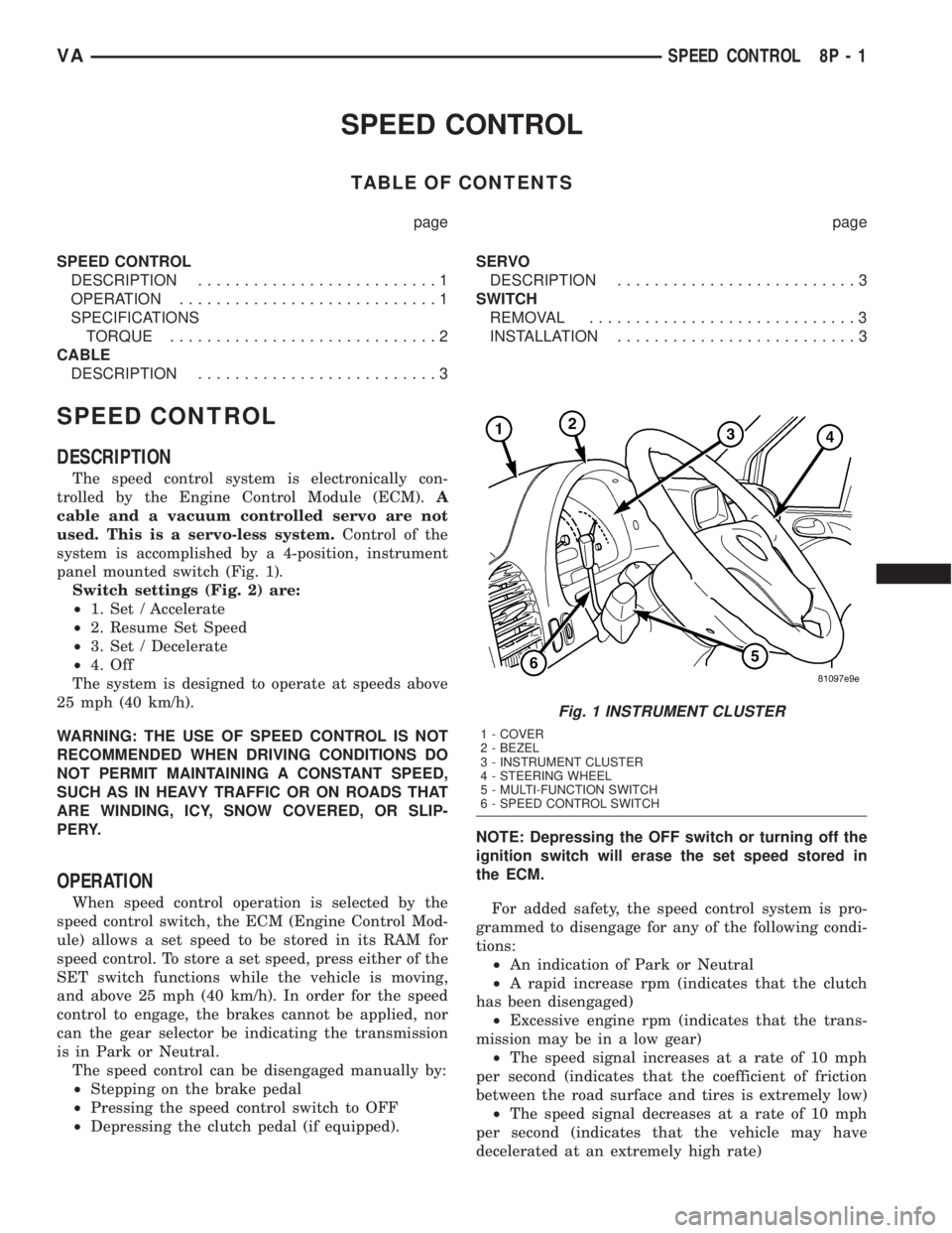
system is accomplished by a 4-position, instrument
panel mounted switch (Fig. 1).
Switch settings (Fig. 2) are:
²1. Set / Accelerate
²2. Resume Set Speed
²3. Set / Decelerate
²4. Off
The system is designed to operate at speeds above
25 mph (40 km/h).
WARNING: THE USE OF SPEED CONTROL IS NOT
RECOMMENDED WHEN DRIVING CONDITIONS DO
NOT PERMIT MAINTAINING A CONSTANT SPEED,
SUCH AS IN HEAVY TRAFFIC OR ON ROADS THAT
ARE WINDING, ICY, SNOW COVERED, OR SLIP-
PERY.
OPERATION
When speed control operation is selected by the
speed control switch, the ECM (Engine Control Mod-
ule) allows a set speed to be stored in its RAM for
speed control. To store a set speed, press either of the
SET switch functions while the vehicle is moving,
and above 25 mph (40 km/h). In order for the speed
control to engage, the brakes cannot be applied, nor
can the gear selector be indicating the transmission
is in Park or Neutral.
The speed control can be disengaged manually by:
²Stepping on the brake pedal
²Pressing the speed control switch to OFF
²Depressing the clutch pedal (if equipped).NOTE: Depressing the OFF switch or turning off the
ignition switch will erase the set speed stored in
the ECM.
For added safety, the speed control system is pro-
grammed to disengage for any of the following condi-
tions:
²An indication of Park or Neutral
²A rapid increase rpm (indicates that the clutch
has been disengaged)
²Excessive engine rpm (indicates that the trans-
mission may be in a low gear)
²The speed signal increases at a rate of 10 mph
per second (indicates that the coefficient of friction
between the road surface and tires is extremely low)
²The speed signal decreases at a rate of 10 mph
per second (indicates that the vehicle may have
decelerated at an extremely high rate)
Fig. 1 INSTRUMENT CLUSTER
1 - COVER
2 - BEZEL
3 - INSTRUMENT CLUSTER
4 - STEERING WHEEL
5 - MULTI-FUNCTION SWITCH
6 - SPEED CONTROL SWITCH
VASPEED CONTROL 8P - 1
Page 277 of 1232

VEHICLE THEFT SECURITY
TABLE OF CONTENTS
page page
VEHICLE THEFT SECURITY
DESCRIPTION..........................1
OPERATION............................1
DIAGNOSIS AND TESTING - VEHICLE THEFT
SECURITY............................1
INTRUSION SENSOR
REMOVAL.............................2
INSTALLATION..........................2
SECURITY SYSTEM MODULE
REMOVAL.............................2
INSTALLATION..........................2SENTRY KEY REMOTE ENTRY MODULE
DESCRIPTION..........................2
OPERATION............................3
REMOVAL.............................3
INSTALLATION..........................4
SIREN
REMOVAL.............................4
INSTALLATION..........................4
TRANSPONDER KEY
DESCRIPTION..........................5
OPERATION............................5
VEHICLE THEFT SECURITY
DESCRIPTION
An anti-theft alarm with battery powered horn is
available as an option and includes interior monitor-
ing, anti-tow away protection and rear window mon-
itoring based on the heater wires. The alarm is
automatically activated when the central locking sys-
tem is operated.
The alarm will sound when any of the following
occur:
²A door is opened
²A door is unlocked from inside the vehicle
²The hood is opened
²The vehicle is raised at the front or rear
²The trailer wire harness is disconnected
²Movements inside the vehicle
²The central locking is unlocked by a key at any
other door than the driver's door
The alarm is functional about 30 seconds after the
vehicle is locked using the RKE transmitter or the
key in the driver's door. Activation is indicated by the
indicator lights flashing three times and the warning
lamp flashing in the switch. If persons or animals
remain in the locked vehicle, the operator should
switch off the interior monitor to avoid a false alarm.
OPERATION
The anti-theft alarm is activated/deactivated by
locking/unlocking the vehicle with the remote trans-
mitter or with the key at the driver's door. The key
must be held in the locking position for more than
two seconds. Activation is indicated by the turn sig-
nal lights flashing once. Unlocking the vehicle at one
of the other doors will trigger an alarm.The interior monitoring system included in the
anti-theft alarm is based on ultrasonics and triggers
an alarm if an object intrudes the interior of the
vehicle or if any movement is detected inside the
vehicle. For proper and effective protection, all win-
dows and the sunroof must be closed.
To switch off the interior monitoring system and /
or the anti-tow away protection, a switch with LED
indicator light is provided in the switch panel. An
alarm button enables the operator to trigger an
alarm manually and to lock all doors if they are
closed. Triggering an alarm makes the horn sound
and the turn signals flash until the alarm is switched
off.
The anti-theft alarm control unit includes a gradi-
ent indicator as anti-tow away protection. The gradi-
ent indicator triggers an audible and visual alarm if
the vehicle is lifted (to tow away or to remove the
wheels). The alarm remains effective even if the bat-
tery is disconnected as the horn is powered by its
own battery. The interior monitoring system should
be switched off if people and/or animals are left in
the vehicle.
DIAGNOSIS AND TESTING - VEHICLE THEFT
SECURITY
Any diagnosis of the Vehicle Theft Security
system should begin with the use of the DRB
IIItdiagnostic tool. For information on the use
of the DRB IIIt, refer to the appropriate Diag-
nostic Service Manual.
VAVEHICLE THEFT SECURITY 8Q - 1
Page 279 of 1232
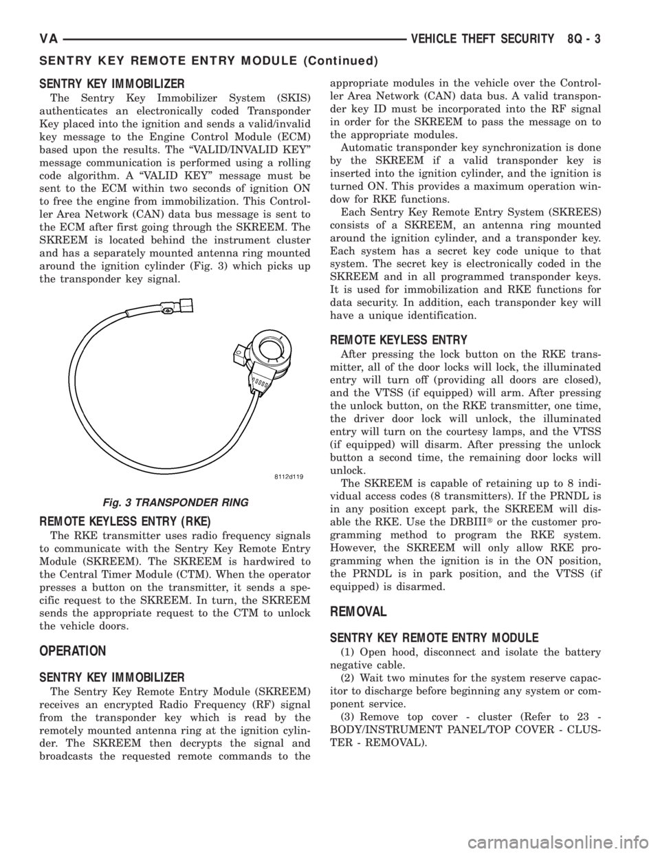
SENTRY KEY IMMOBILIZER
The Sentry Key Immobilizer System (SKIS)
authenticates an electronically coded Transponder
Key placed into the ignition and sends a valid/invalid
key message to the Engine Control Module (ECM)
based upon the results. The ªVALID/INVALID KEYº
message communication is performed using a rolling
code algorithm. A ªVALID KEYº message must be
sent to the ECM within two seconds of ignition ON
to free the engine from immobilization. This Control-
ler Area Network (CAN) data bus message is sent to
the ECM after first going through the SKREEM. The
SKREEM is located behind the instrument cluster
and has a separately mounted antenna ring mounted
around the ignition cylinder (Fig. 3) which picks up
the transponder key signal.
REMOTE KEYLESS ENTRY (RKE)
The RKE transmitter uses radio frequency signals
to communicate with the Sentry Key Remote Entry
Module (SKREEM). The SKREEM is hardwired to
the Central Timer Module (CTM). When the operator
presses a button on the transmitter, it sends a spe-
cific request to the SKREEM. In turn, the SKREEM
sends the appropriate request to the CTM to unlock
the vehicle doors.
OPERATION
SENTRY KEY IMMOBILIZER
The Sentry Key Remote Entry Module (SKREEM)
receives an encrypted Radio Frequency (RF) signal
from the transponder key which is read by the
remotely mounted antenna ring at the ignition cylin-
der. The SKREEM then decrypts the signal and
broadcasts the requested remote commands to theappropriate modules in the vehicle over the Control-
ler Area Network (CAN) data bus. A valid transpon-
der key ID must be incorporated into the RF signal
in order for the SKREEM to pass the message on to
the appropriate modules.
Automatic transponder key synchronization is done
by the SKREEM if a valid transponder key is
inserted into the ignition cylinder, and the ignition is
turned ON. This provides a maximum operation win-
dow for RKE functions.
Each Sentry Key Remote Entry System (SKREES)
consists of a SKREEM, an antenna ring mounted
around the ignition cylinder, and a transponder key.
Each system has a secret key code unique to that
system. The secret key is electronically coded in the
SKREEM and in all programmed transponder keys.
It is used for immobilization and RKE functions for
data security. In addition, each transponder key will
have a unique identification.
REMOTE KEYLESS ENTRY
After pressing the lock button on the RKE trans-
mitter, all of the door locks will lock, the illuminated
entry will turn off (providing all doors are closed),
and the VTSS (if equipped) will arm. After pressing
the unlock button, on the RKE transmitter, one time,
the driver door lock will unlock, the illuminated
entry will turn on the courtesy lamps, and the VTSS
(if equipped) will disarm. After pressing the unlock
button a second time, the remaining door locks will
unlock.
The SKREEM is capable of retaining up to 8 indi-
vidual access codes (8 transmitters). If the PRNDL is
in any position except park, the SKREEM will dis-
able the RKE. Use the DRBIIItor the customer pro-
gramming method to program the RKE system.
However, the SKREEM will only allow RKE pro-
gramming when the ignition is in the ON position,
the PRNDL is in park position, and the VTSS (if
equipped) is disarmed.
REMOVAL
SENTRY KEY REMOTE ENTRY MODULE
(1) Open hood, disconnect and isolate the battery
negative cable.
(2) Wait two minutes for the system reserve capac-
itor to discharge before beginning any system or com-
ponent service.
(3) Remove top cover - cluster (Refer to 23 -
BODY/INSTRUMENT PANEL/TOP COVER - CLUS-
TER - REMOVAL).
Fig. 3 TRANSPONDER RING
VAVEHICLE THEFT SECURITY 8Q - 3
SENTRY KEY REMOTE ENTRY MODULE (Continued)
Page 281 of 1232
TRANSPONDER KEY
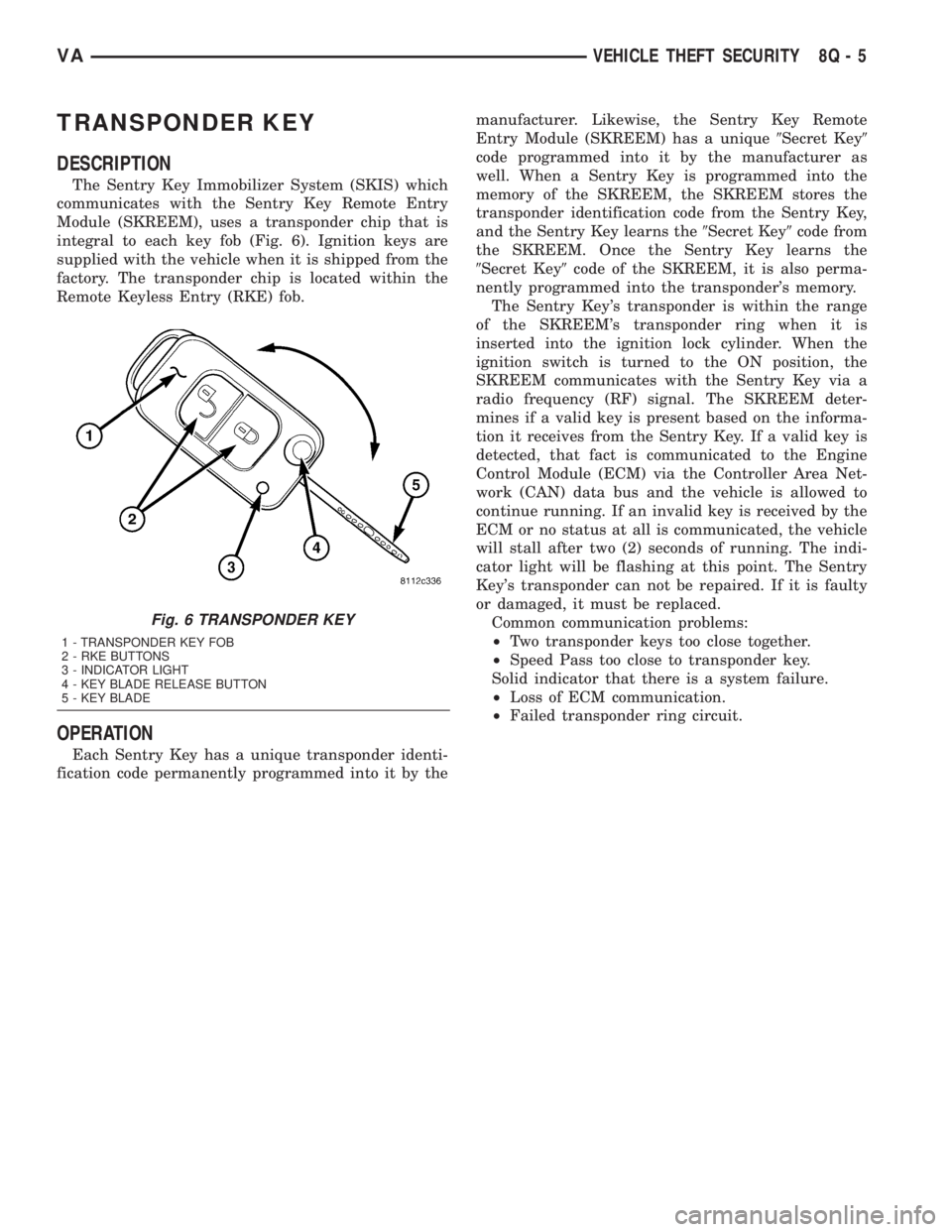
DESCRIPTION
The Sentry Key Immobilizer System (SKIS) which
communicates with the Sentry Key Remote Entry
Module (SKREEM), uses a transponder chip that is
integral to each key fob (Fig. 6). Ignition keys are
supplied with the vehicle when it is shipped from the
factory. The transponder chip is located within the
Remote Keyless Entry (RKE) fob.
OPERATION
Each Sentry Key has a unique transponder identi-
fication code permanently programmed into it by themanufacturer. Likewise, the Sentry Key Remote
Entry Module (SKREEM) has a unique9Secret Key9
code programmed into it by the manufacturer as
well. When a Sentry Key is programmed into the
memory of the SKREEM, the SKREEM stores the
transponder identification code from the Sentry Key,
and the Sentry Key learns the9Secret Key9code from
the SKREEM. Once the Sentry Key learns the
9Secret Key9code of the SKREEM, it is also perma-
nently programmed into the transponder's memory.
The Sentry Key's transponder is within the range
of the SKREEM's transponder ring when it is
inserted into the ignition lock cylinder. When the
ignition switch is turned to the ON position, the
SKREEM communicates with the Sentry Key via a
radio frequency (RF) signal. The SKREEM deter-
mines if a valid key is present based on the informa-
tion it receives from the Sentry Key. If a valid key is
detected, that fact is communicated to the Engine
Control Module (ECM) via the Controller Area Net-
work (CAN) data bus and the vehicle is allowed to
continue running. If an invalid key is received by the
ECM or no status at all is communicated, the vehicle
will stall after two (2) seconds of running. The indi-
cator light will be flashing at this point. The Sentry
Key's transponder can not be repaired. If it is faulty
or damaged, it must be replaced.
Common communication problems:
²Two transponder keys too close together.
²Speed Pass too close to transponder key.
Solid indicator that there is a system failure.
²Loss of ECM communication.
²Failed transponder ring circuit.
Fig. 6 TRANSPONDER KEY
1 - TRANSPONDER KEY FOB
2 - RKE BUTTONS
3 - INDICATOR LIGHT
4 - KEY BLADE RELEASE BUTTON
5 - KEY BLADE
VAVEHICLE THEFT SECURITY 8Q - 5
Page 285 of 1232
The longer blade is installed on the left (driver) side
of the windshield.
²Wiper Linkage- The wiper pivots are the only
visible components of the wiper linkage. The remain-
der of the linkage is concealed within the engine
compartment just behind the hood opening. The
wiper linkage module includes the two wiper drive
links, the wiper motor crank arm, the two wiper piv-
ots, and the linkage and motor mounting bracket.
²Wiper Motor- The wiper motor is secured to
the wiper linkage module bracket on the underside of
the cowl panel within the engine compartment. The
wiper motor output shaft and crank arm extend
through a clearance hole in the mounting bracket,
where they are connected to a crank arm that drives
the wiper linkage.
²Wiper Relay- The wiper relay is located in a
dedicated receptacle on the lower left surface of the
fuse block underneath the steering column behind
the fuse access panel and the steering column open-
ing panel.
²Wiper, Turn Signals, Engine Start Control
Module- The wiper, turn signals and engine start
control module is integral to the fuse block located
underneath the steering column. The fuse block is
concealed behind the fuse access panel and the steer-
ing column opening panel, where it is secured with
screws to the steering column. The wiper, turn sig-
nals and engine start control module contains the
intermittent wipe logic circuitry, which includes
active electronic elements that allow it to provide the
intermittent wipe delay and the wipe-after-wash fea-
tures of the intermittent wipe system based upon
numerous hard wired inputs, then provides the
proper programmed hard wired control output to
operate the wiper motor through the wiper relay.
Hard wired circuitry connects the wiper and
washer system components to the electrical system of
the vehicle. These hard wired circuits are integral to
several wire harnesses, which are routed throughout
the vehicle and retained by many different methods.
These circuits may be connected to each other, to the
vehicle electrical system and to the wiper and washer
system components through the use of a combination
of soldered splices, splice block connectors, and many
different types of wire harness terminal connectors
and insulators. Refer to the appropriate wiring infor-
mation. The wiring information includes wiring dia-
grams, proper wire and connector repair procedures,
further details on wire harness routing and reten-
tion, as well as pin-out and location views for the
various wire harness connectors, splices and grounds.OPERATING MODES
The components of the wiper and washer system
are designed to provide the following operating
modes:
²Continuous Wipe Mode- The two-speed wiper
motor, the internal circuitry of the multi-function
switch, and the wiper relay work in concert to pro-
vide two continuous wipe cycles, low speed or high
speed.
²Intermittent Wipe Mode- The internal cir-
cuitry of the multi-function switch, the intermittent
wipe circuitry of the wiper, turn signals and engine
start control module in the fuse block, and the wiper
relay work in concert to provide an intermittent wipe
mode with a single, fixed delay interval.
²Pulse Wipe Mode- The internal circuitry of
the multi-function switch and the wiper relay work
in concert to provide a pulse wipe mode that will
allow the wiper motor to be operated for a single,
complete wipe cycle.
²Washer Mode- When the washer system is
activated with the multi-function switch while the
wiper system is operating, washer fluid will be dis-
pensed onto the windshield glass through the washer
nozzles for as long as the washer pump/motor is
energized.
²Wipe-After-Wash Mode- The intermittent
wipe circuitry of the wiper, turn signals and engine
start control module in the fuse block, and the wiper
relay provide a wipe-after-wash feature. If the wipers
are turned Off, this feature will operate the washer
pump/motor and the wipers for as long as the washer
system is activated, then provide several additional
wipe cycles after the washer system is deactivated
before parking the wiper blades near the base of the
windshield.
OPERATION
The wiper and washer system is designed to pro-
vide the vehicle operator with a convenient, safe, and
reliable means of maintaining visibility through the
windshield glass. The various components of this sys-
tem are designed to convert electrical energy pro-
duced by the vehicle electrical system into the
mechanical action of the wiper blades to wipe the
outside surface of the glass, as well as into the
hydraulic action of the washer system to apply
washer fluid stored in an on-board reservoir to the
area of the glass to be wiped. When combined, these
components provide the means to effectively main-
tain clear visibility for the vehicle operator by remov-
ing excess accumulations of rain, snow, bugs, mud, or
other minor debris from the outside windshield glass
surface that might be encountered while driving the
vehicle under numerous types of inclement operating
conditions.
VAWIPERS/WASHERS 8R - 3
WIPERS/WASHERS (Continued)