2005 MERCEDES-BENZ SPRINTER display
[x] Cancel search: displayPage 191 of 1232
OPERATION
The multi-function indicator has several display
capabilities including odometer, trip odometer, clock,
engine oil level data, gear selector indicator
(PRNDL), certain diagnostic information and, on
vehicles so equipped, an optional Active Service SYS-
Tem (ASSYST) engine oil maintenance indicator and
an optional outside ambient temperature indicator.
The multi-function indicator is completely controlled
by the instrument cluster logic circuit, and that logic
will allow this indication to be viewed whenever the
multi-function indicator Liquid Crystal Display
(LCD) is activated. Therefore, the indicator remains
functional regardless of the ignition switch position.
With the ignition switch in the Off or Accessory posi-
tions and the key removed from the ignition lock cyl-
inder, the display is activated when the park lamps
are turned On or, for about thirty seconds after any
one of the multi-function indicator switch push but-
tons is depressed. Otherwise, the display unit is
active for about thirty seconds after the key is
inserted into the ignition lock cylinder, and inactive
about thirty seconds after the key is removed from
the ignition lock cylinder.
The multi-function indicator ªmiº (miles) or
ªkmº(kilometers) switch push button is used to con-
trol the odometer/trip odometer display modes. The
multi-function indicator clock switch push button is
used to control the clock/outside temperature display
modes. The multi-function indicator ª+º (plus) and
ª2º (minus) switch push buttons are used to adjust
the cluster general illumination dimming level, the
clock, and other cluster settings. See the owner's
manual in the vehicle glove box for more information
on the features, use, operation and setting proce-
dures for the various standard and optional multi-
function indicator displays.
Proper testing of the multi-function indicator LCD
unit, the CAN data bus and the electronic data bus
message inputs to the instrument cluster that control
some of the multi-function indicator functions
requires the use of a DRBIIItscan tool. Refer to the
appropriate diagnostic information. Additional details
for the odometer/trip odometer, the clock, the gear
selector indicator, the ambient temperature indicator
and the ASSYST warning and reminder functions of
the multi-function indicator may be found elsewhere
in this service information.
ODOMETER
DESCRIPTION
An odometer and trip odometer are standard
equipment in all instrument clusters. The odometer
and trip odometer values are displayed on the leftside of the multi-function indicator Liquid Crystal
Display (LCD). The LCD is soldered onto the cluster
electronic circuit board and is visible through a win-
dow with a clear lens located near the lower edge of
the instrument cluster, directly below the speedome-
ter. However, the odometer and trip odometer infor-
mation are not displayed simultaneously. The ªmiº
(miles) or ªkmº (kilometers) switch on the instrument
cluster circuit board toggles the display between
odometer and trip odometer modes by depressing the
switch push button that extends through the lower
edge of the cluster lens, directly below the multi-
function indicator LCD.
The odometer and trip odometer information is
stored in the instrument cluster memory. This infor-
mation can be increased when the proper inputs are
provided to the instrument cluster, but the informa-
tion cannot be decreased. The odometer can display
values up to 999,999 kilometers (999,999 miles). The
odometer latches at these values, and will not roll
over to zero. The trip odometer can display values up
to 999.9 kilometers (999.9 miles) before it rolls over
to zero. The odometer display does not have a deci-
mal point and will not show values less than a full
unit (kilometer or mile), while the trip odometer dis-
play does have a decimal point and will show tenths
of a unit (kilometer or mile). The unit of measure
(kilometers or miles) for the odometer and trip odom-
eter display is imprinted on the cluster overlay below
the left end of the LCD. The unit of measure for the
instrument cluster odometer/trip odometer is selected
at the time that it is manufactured, and cannot be
changed.
The indications of the odometer/trip odometer are
not visible when the LCD is not illuminated. When
illuminated the indications appear as dark charac-
ters silhouetted against an amber field. When the
exterior lighting is turned Off, the display is illumi-
nated at maximum brightness. When the exterior
lighting is turned On the display illumination level
can be adjusted in concert with the cluster general
illumination lighting using the plus and minus multi-
function indicator push buttons. The odometer has a
ªRental Carº mode, which will activate the multi-
function indicator LCD and illuminate the odometer
information for about thirty seconds after one of the
multi-function indicator push buttons is momentarily
depressed, or after the key is inserted into the igni-
tion switch lock cylinder with the ignition switch in
the Off position.
The odometer/trip odometer and the miles/kilome-
ters switch, and the miles/kilometers switch push
button are serviced as a unit with the instrument
cluster.
VAINSTRUMENT CLUSTER 8J - 21
MULTI-FUNCTION INDICATOR (Continued)
Page 192 of 1232
OPERATION
The odometer and trip odometer give an indication
to the vehicle operator of the distance the vehicle has
traveled. This indicator is controlled by the instru-
ment cluster circuitry based upon cluster program-
ming and electronic messages received by the cluster
from the Controller Anti-lock Brake (CAB) over the
Controller Area Network (CAN) data bus. The odom-
eter and trip odometer information is displayed by
the multi-function indicator Liquid Crystal Display
(LCD). The LCD will display the odometer informa-
tion whenever it is activated, and will display the
last previously selected odometer or trip odometer
information when the ignition switch is turned to the
On position. The instrument cluster circuitry controls
the LCD and provides the following features:
²Odometer/Trip Odometer Display Toggling-
Actuating the multi-function indicator ªmiº (miles) or
ªkmº (kilometers) switch push button momentarily
with the LCD illuminated will toggle the display
between the odometer and trip odometer information.
Each time the LCD is illuminated with the ignition
switch in the On or Start positions, the display will
automatically return to the last mode previously
selected (odometer or trip odometer).
²Trip Odometer Reset- When the multi-func-
tion indicator ªmiº (miles) or ªkmº (kilometers) switch
push button is pressed and held for longer than
about two seconds, the trip odometer will be reset to
000.0 kilometers (miles). The LCD must be display-
ing the trip odometer information in order for the
trip odometer information to be reset.
The CAB continually monitors the vehicle speed
pulse information received from the four wheel speed
sensors, then sends the proper distance messages to
the instrument cluster. For proper diagnosis of the
wheel speed sensors, the CAB, the CAN data bus, or
the electronic message inputs to the instrument clus-
ter that control the odometer/trip odometer, a
DRBIIItscan tool is required. Refer to the appropri-
ate diagnostic information.
SEATBELT INDICATOR
DESCRIPTION
A seatbelt indicator is standard equipment on all
instrument clusters. The seatbelt indicator is located
near the lower edge of the instrument cluster, to the
right of the multi-function indicator display. The
seatbelt indicator consists of the International Con-
trol and Display Symbol icon for ªSeat Beltº
imprinted within a rectangular cutout in the opaque
layer of the instrument cluster overlay. The dark
outer layer of the overlay prevents the indicator from
being clearly visible when it is not illuminated. A redLight Emitting Diode (LED) behind the cutout in the
opaque layer of the overlay causes the icon to appear
silhouetted against a red field through the translu-
cent outer layer of the overlay when the indicator is
illuminated from behind by the LED, which is sol-
dered onto the instrument cluster electronic circuit
board. The seatbelt indicator is serviced as a unit
with the instrument cluster.
OPERATION
The seatbelt indicator gives an indication to the
vehicle operator of the status of the driver side front
seat belt. This indicator is controlled by a transistor
on the instrument cluster circuit board based upon
cluster programming and a hard wired input received
from the seat belt switch on the driver side front seat
belt. The seatbelt indicator Light Emitting Diode
(LED) is completely controlled by the instrument
cluster logic circuit, and that logic will only allow
this indicator to operate when the instrument cluster
detects that the ignition switch is in the On position.
Therefore, the LED will always be off when the igni-
tion switch is in any position except On. The LED
only illuminates when it is provided a path to ground
by the instrument cluster transistor. The instrument
cluster will turn on the seatbelt indicator for the fol-
lowing reasons:
²Seatbelt Reminder Function- Each time the
cluster detects that the ignition switch has been
turned to the On position the seatbelt indicator will
be illuminated as a reminder for about six seconds,
or until the ignition switch is turned to the Off posi-
tion, whichever occurs first. This reminder function
will occur regardless of the status of the input
received by the cluster from the driver side front seat
belt switch.
²Driver Side Front Seat Belt Switch Input-
Following the seatbelt reminder function, each time
the cluster detects ground on the seatbelt indicator
driver circuit (seat belt switch closed = seatbelt
unbuckled) with the ignition switch in the On posi-
tion, the seatbelt indicator will be illuminated. The
seatbelt indicator remains illuminated until the seat
belt switch input to the cluster is an open circuit
(seat belt switch open = seatbelt buckled), or until
the ignition switch is turned to the Off position,
whichever occurs first.
²Airbag Indicator Malfunction- Following the
seatbelt reminder function, each time the cluster
detects a malfunction in the airbag (SRS) indicator or
the airbag indicator circuit, the cluster will flash the
seatbelt indicator on and off. The cluster will con-
tinue to flash the seatbelt indicator until the airbag
indicator circuit fault is resolved, or until the ignition
switch is turned to the Off position, whichever occurs
first.
8J - 22 INSTRUMENT CLUSTERVA
ODOMETER (Continued)
Page 195 of 1232
TRACTION CONTROL
MALFUNCTION INDICATOR
DESCRIPTION
A traction control (ASR) malfunction indicator is
standard equipment on all instrument clusters. The
traction control malfunction indicator is located near
the lower edge of the instrument cluster, to the right
of the multi-function indicator display. The traction
control malfunction indicator consists of an icon that
graphically depicts a tire and two skid marks
imprinted within a rectangular cutout in the opaque
layer of the instrument cluster overlay. The dark
outer layer of the overlay prevents the indicator from
being clearly visible when it is not illuminated. An
amber Light Emitting Diode (LED) behind the cutout
in the opaque layer of the overlay causes the icon to
appear silhouetted against an amber field through
the translucent outer layer of the overlay when the
indicator is illuminated from behind by the LED,
which is soldered onto the instrument cluster elec-
tronic circuit board. The traction control malfunction
indicator is serviced as a unit with the instrument
cluster.
OPERATION
The traction control (ASR) malfunction indicator
gives the vehicle operator an indication when the
traction control system is faulty or inoperative. This
indicator is controlled by a transistor on the instru-
ment cluster circuit board based upon cluster pro-
gramming and electronic messages received by the
cluster from the Controller Antilock Brake (CAB)
over the Controller Area Network (CAN) data bus.
The traction control malfunction indicator Light
Emitting Diode (LED) is completely controlled by the
instrument cluster logic circuit, and that logic will
only allow this indicator to operate when the instru-
ment cluster detects that the ignition switch is in the
On position. Therefore, the LED will always be off
when the ignition switch is in any position except
On. The LED only illuminates when it is provided a
path to ground by the instrument cluster transistor.
The instrument cluster will turn on the traction con-
trol malfunction indicator for the following reasons:
²Bulb Test- Each time the ignition switch is
turned to the On position the traction control indica-
tor is illuminated as a bulb test until the engine is
started.
²Traction Control (ASR) Malfunction Indica-
tor Lamp-On Message- Each time the cluster
receives a traction control malfunction indicator
lamp-on message from the CAB, the indicator will be
illuminated. The indicator remains illuminated until
the cluster receives a lamp-off message from theCAB, or until the ignition switch is turned to the Off
position, whichever occurs first.
The CAB continually monitors the traction control
(ASR) system circuits and sensors to decide whether
the system is in good operating condition. The CAB
then sends the proper lamp-on or lamp-off messages
to the instrument cluster. If the CAB sends a
lamp-on message after the bulb test, it indicates that
the CAB has detected a system malfunction and that
the traction control (ASR) system has become inoper-
ative. The CAB will store a Diagnostic Trouble Code
(DTC) for any malfunction it detects. In addition, if
the traction control malfunction indicator is illumi-
nated, the CAB will deactivate an activated traction
control system and engine power output may be
reduced. See the owner's manual in the vehicle glove
box for more information on the features, use, activa-
tion and deactivation of the traction control (ASR)
system. For proper diagnosis of the traction control
system, the CAB, the CAN data bus, or the electronic
message inputs to the instrument cluster that control
the traction control malfunction indicator, a DRBIIIt
scan tool is required. Refer to the appropriate diag-
nostic information.
TURN SIGNAL INDICATOR
DESCRIPTION
Two turn signal indicators, one right and one left,
are standard equipment on all instrument clusters.
The turn signal indicators are located near the upper
edge of the instrument cluster, one to each side of the
speedometer. Each turn signal indicator consists of a
arrow-shaped cutout of the International Control and
Display Symbol icon for ªTurn Warningº in the
opaque layer of the instrument cluster overlay. The
dark outer layer of the overlay prevents these icons
from being clearly visible when they are not illumi-
nated. A green Light Emitting Diode (LED) behind
each turn signal indicator cutout in the opaque layer
of the overlay causes the icon to appear in green
through the translucent outer layer of the overlay
when the indicator is illuminated from behind by the
LED, which is soldered onto the instrument cluster
electronic circuit board. The turn signal indicators
are serviced as a unit with the instrument cluster.
OPERATION
The turn signal indicators give an indication to the
vehicle operator that the turn signal (left or right
indicator flashing) or hazard warning (both left and
right indicators flashing) have been selected and are
operating. These indicators are controlled by transis-
tors on the instrument cluster electronic circuit board
based upon the cluster programming and a hard
VAINSTRUMENT CLUSTER 8J - 25
Page 196 of 1232
wired input received by the cluster from the turn sig-
nal relay through the turn signal and hazard warn-
ing switch circuitry of the multi-function switch on
the left and right turn signal circuits. Each turn sig-
nal indicator Light Emitting Diode (LED) is com-
pletely controlled by the instrument cluster logic
circuit, and that logic will allow this indicator to
operate whenever the instrument cluster receives a
battery current input on the fused B(+) circuit.
Therefore, each LED can be illuminated regardless of
the ignition switch position. The LED only illumi-
nates when it is provided a path to ground by the
instrument cluster transistor. The instrument cluster
will turn on the turn signal indicators for the follow-
ing reasons:
²Turn Signal Input- Each time the cluster
detects a turn signal input from the turn signal relay
through the closed turn signal switch circuitry of the
multi-function switch on the hard wired left or right
turn signal circuit, the requested turn signal lamps
and turn signal indicator will be flashed on and off,
and a contactless relay soldered onto the cluster elec-
tronic circuit board will produce a clicking sound to
emulate a conventional turn signal flasher. The turn
signals and the turn signal indicators continue to
flash on and off until the turn signal switch circuitry
of the multi-function switch is opened, or until the
ignition switch is turned to the Off position, which-
ever occurs first.
²Hazard Warning Input- Each time the cluster
detects a hazard warning input from the turn signal
relay through the closed hazard warning switch cir-
cuitry of the multi-function switch on the hard wired
left and right turn signal circuits, all of the turn sig-
nal lamps and both turn signal indicators will be
flashed on and off, and a contactless relay soldered
onto the cluster electronic circuit board will produce
a clicking sound to emulate a conventional hazard
warning flasher. The turn signals and the turn signal
indicators continue to flash on and off until the haz-
ard warning switch circuitry of the multi-function
switch is opened.
An electronic wipers, turn signals and engine start
control module located within the fuse block beneath
the steering column monitors the turn signal circuits
and controls the flash rate of the turn signal relay.
The instrument cluster continually monitors the
right and left turn signal circuits to determine the
proper turn signal and hazard warning indicator
operation, then flashes the proper turn signal indica-
tors and the contactless relay on and off accordingly.
The multi-function switch, the turn signal relay and
the left and right turn signal circuits to the instru-
ment cluster can be diagnosed using conventional
diagnostic tools and methods. For proper diagnosis of
the wipers, turn signals and engine start controlmodule within the fuse block or the instrument clus-
ter circuitry that controls the turn signal indicators
and the contactless relay, a DRBIIItscan tool is
required. Refer to the appropriate diagnostic infor-
mation.
WAIT-TO-START INDICATOR
DESCRIPTION
A wait-to-start indicator is standard equipment in
all instrument clusters. The wait-to-start indicator is
located near the lower edge of the instrument cluster,
to the right of the multi-function indicator display.
The wait-to-start indicator consists of the Interna-
tional Control and Display Symbol icon for ªDiesel
Preheatº imprinted within a rectangular cutout in
the opaque layer of the instrument cluster overlay.
The dark outer layer of the overlay prevents the indi-
cator from being clearly visible when it is not illumi-
nated. An amber Light Emitting Diode (LED) behind
the cutout in the opaque layer of the overlay causes
the icon to appear silhouetted against an amber field
through the translucent outer layer of the overlay
when the indicator is illuminated from behind by the
LED, which is soldered onto the instrument cluster
electronic circuit board. The wait-to-start indicator is
serviced as a unit with the instrument cluster.
OPERATION
The wait-to-start indicator gives an indication to
the vehicle operator when the diesel engine glow
plugs are energized in their pre-heat operating mode.
This indicator is controlled by a transistor on the
instrument cluster circuit board based upon cluster
programming and electronic messages received by
the cluster from the Engine Control Module (ECM)
over the Controller Area Network (CAN) data bus.
The wait-to-start indicator Light Emitting Diode
(LED) is completely controlled by the instrument
cluster logic circuit, and that logic will only allow
this indicator to operate when the instrument cluster
detects that the ignition switch is in the On position.
Therefore, the LED will always be off when the igni-
tion switch is in any position except On. The LED
only illuminates when it is provided a path to ground
by the instrument cluster transistor. The instrument
cluster will turn on the wait-to-start indicator for the
following reasons:
²Bulb Test- Each time the ignition switch is
turned to the On position the wait-to-start indicator
is illuminated for about two seconds as a bulb test.
²Wait-To-Start Lamp-On Message- Each time
the cluster receives a wait-to-start lamp-on message
from the ECM indicating that the diesel engine glow
plugs are energized in their pre-heat operating mode,
8J - 26 INSTRUMENT CLUSTERVA
TURN SIGNAL INDICATOR (Continued)
Page 197 of 1232
the wait-to-start indicator will be illuminated. The
indicator remains illuminated until the cluster
receives a wait-to-start lamp-off message indicating
that the pre-heat mode of the glow plugs has been
completed, until the ECM detects that the engine is
running, or until the ignition switch is turned to the
Off position, whichever occurs first.
The ECM continually monitors the engine coolant
temperature sensor to determine when the glow
plugs need to be energized in their pre-heat operat-
ing mode. The ECM then sends the proper wait-to-
start lamp-on and lamp-off messages to the
instrument cluster. If the instrument cluster turns on
the indicator after the engine is started, it may indi-
cate that a malfunction has occurred and that the
engine glow control system requires service. The
ECM will store a Diagnostic Trouble Code (DTC) for
any malfunction it detects. For proper diagnosis of
the engine coolant temperature sensor, the engine
glow control system and circuits, the ECM, the CAN
data bus, or the electronic message inputs to the
instrument cluster that control the wait-to-start indi-
cator, a DRBIIItscan tool is required. Refer to the
appropriate diagnostic information.
WASHER FLUID INDICATOR
DESCRIPTION
A washer fluid indicator is standard equipment on
all instrument clusters. However, this indicator is
only functional on vehicles equipped with an optional
washer fluid level switch integral to the washer
pump/motor unit on the washer reservoir. The
washer fluid indicator is located near the lower edge
of the instrument cluster, to the right of the multi-
function indicator display. The washer fluid indicator
consists of the International Control and Display
Symbol icon for ªWindshield Washer Fluidº imprinted
within a rectangular cutout in the opaque layer of
the instrument cluster overlay. The dark outer layer
of the overlay prevents the indicator from being
clearly visible when it is not illuminated. An amber
Light Emitting Diode (LED) behind the cutout in the
opaque layer of the overlay causes the icon to appear
silhouetted against an amber field through the trans-
lucent outer layer of the overlay when the indicator
is illuminated from behind by the LED, which is sol-
dered onto the instrument cluster electronic circuit
board. The washer fluid indicator is serviced as a
unit with the instrument cluster.
OPERATION
The washer fluid indicator gives an indication to
the vehicle operator that the fluid level in the washer
reservoir is low. This indicator is controlled by theinstrument cluster circuit board based upon cluster
programming and a hard wired input from the
optional washer fluid level switch that is integral to
the washer pump/motor unit. The washer fluid indi-
cator is completely controlled by the instrument clus-
ter logic circuit, and that logic will only allow this
indicator to operate when the instrument cluster
detects that the ignition switch is in the On position.
Therefore, the indicator will always be off when the
ignition switch is in any position except On. The indi-
cator only illuminates when it is switched to ground
by the instrument cluster circuitry. The instrument
cluster will turn on the washer fluid indicator for the
following reasons:
²Bulb Test- Each time the ignition switch is
turned to the On position the brake wear indicator is
illuminated by the instrument cluster for about two
seconds as a bulb test.
²Washer Fluid Level Switch Input- Each time
the cluster detects ground on the washer fluid switch
sense circuit (washer fluid level switch closed =
washer fluid level low) while the ignition switch is in
the On position, the washer fluid indicator is illumi-
nated. The indicator remains illuminated until the
washer fluid level switch input to the cluster is an
open circuit (washer fluid level switch open = washer
fluid level acceptable), or until the ignition switch is
turned to the Off position, whichever occurs first.
The instrument cluster continually monitors the
washer fluid level switch to determine the level of
the washer fluid. The instrument cluster logic applies
a delay strategy to this input to reduce the negative
effect that fluid sloshing within the reservoir can
have on reliable indicator operation. The washer
fluid level switch and circuit can be diagnosed using
conventional diagnostic tools and methods. For
proper diagnosis of the instrument cluster circuitry
that controls the washer fluid indicator, a DRBIIIt
scan tool is required. Refer to the appropriate diag-
nostic information.
WATER-IN-FUEL INDICATOR
DESCRIPTION
A water-in-fuel indicator is standard equipment in
all instrument clusters. The water-in-fuel indicator is
located near the lower edge of the instrument cluster,
to the left of the multi-function indicator display. The
water-in-fuel indicator consists of the International
Control and Display Symbol icon for ªWater In Fuelº
imprinted within a rectangular cutout in the opaque
layer of the instrument cluster overlay. The dark
outer layer of the overlay prevents the indicator from
being clearly visible when it is not illuminated. An
amber Light Emitting Diode (LED) behind the cutout
VAINSTRUMENT CLUSTER 8J - 27
WAIT-TO-START INDICATOR (Continued)
Page 830 of 1232
DIAGNOSIS AND TESTING - AIR IN FUEL
SYSTEM
Air will enter the fuel system whenever fuel supply
lines, separator filters, injection pump, high-pressure
lines or injectors are removed or disconnected. Air
trapped in the fuel system can result in hard start-
ing, a rough running engine, engine misfire, low
power, excessive smoke and fuel knock.
Inspect the fuel system from the fuel tank to the
injectors for loose connections (Refer to 14 - FUEL
SYSTEM - WARNING). Leaking fuel is an indicator
of loose connections or defective seals. Air can also
enter the fuel system between the fuel tank and the
fuel pump. Inspect the fuel tank and fuel lines for
damage that might allow air into the system.
With the DRBIIItconnected to the vehicle, select
Engine and the select Sensor Display. Page down to
view Fuel Pressure Set Point and Actual Fuel Pres-
sure. Start the engine and observe the Fuel Pressure
Set Point and the Actual Fuel Pressure. If the Actual
Fuel Pressure Oscillates above and below the Fuel
Pressure Set Point in a regular cycle, perform the
Fuel System Air Purge procedure (Refer to 14 -
FUEL SYSTEM - STANDARD PROCEDURE).
If the Actual Fuel Pressure gradually drops below
the Fuel Pressure Set Point then spikes well above
the Fuel Pressure Set Point, replace the fuel pres-
sure solenoid (Refer to 14 - FUEL SYSTEM/FUEL
INJECTION/FUEL PRESSURE SOLENOID -
REMOVAL), then perform the Fuel System Air Purgeprocedure (Refer to 14 - FUEL SYSTEM - STAN-
DARD PROCEDURE).
STANDARD PROCEDURE
STANDARD PROCEDURES - CLEANING FUEL
SYSTEM COMPONENTS
CAUTION: Cleanliness cannot be overemphasized
when handling or replacing diesel fuel system com-
ponents. This especially includes the fuel injectors,
high-pressure fuel lines, fuel rail, and fuel injection
pump. Very tight tolerances are used with these
parts. Dirt contamination could cause rapid part
wear and possible plugging of fuel injector nozzle
tip holes. This in turn could lead to possible engine
misfire. Always wash/clean any fuel system compo-
nent thoroughly before disassembly and then air
dry. DO NOT wire brush injector nozzles when
cleaning. Cap or cover any open part after disas-
sembly. Before assembly, examine each part for
dirt, grease or other contaminants and clean if nec-
essary. When installing new parts, lubricate them
with clean engine oil or clean diesel fuel only.
STANDARD PROCEDURE - DISCONNECTING
AND CONNECTING FUEL LINES
NOTE: Capture and store any fuel spillage in appro-
priately marked containers.
(1) Disconnect negative battery cable.
(2) Push release arm to release position A, as far
as the stop (arrow) (Fig. 2).
(3) Disconnect fuel line.
(4) Immediately return the release arm back to the
assembly position, as far as the stop (Fig. 2).
The release arm must not be left in the release
position for a long time. Connectors left in the
release position for lengthy periods may leak and
must be replaced.
(5) Insert connector into connection in assembly
position (B) (Fig. 2).
(6) Ensure that the connectors are firmly seated
and free of leaks (Fig. 2).
STANDARD PROCEDURES - DRAINING WATER
FROM FUEL FILTER
Refer to Fuel Filter/Water Separator removal/in-
stallation for procedures (Refer to 14 - FUEL SYS-
TEM/FUEL DELIVERY/FUEL FILTER / WATER
SEPARATOR - REMOVAL).
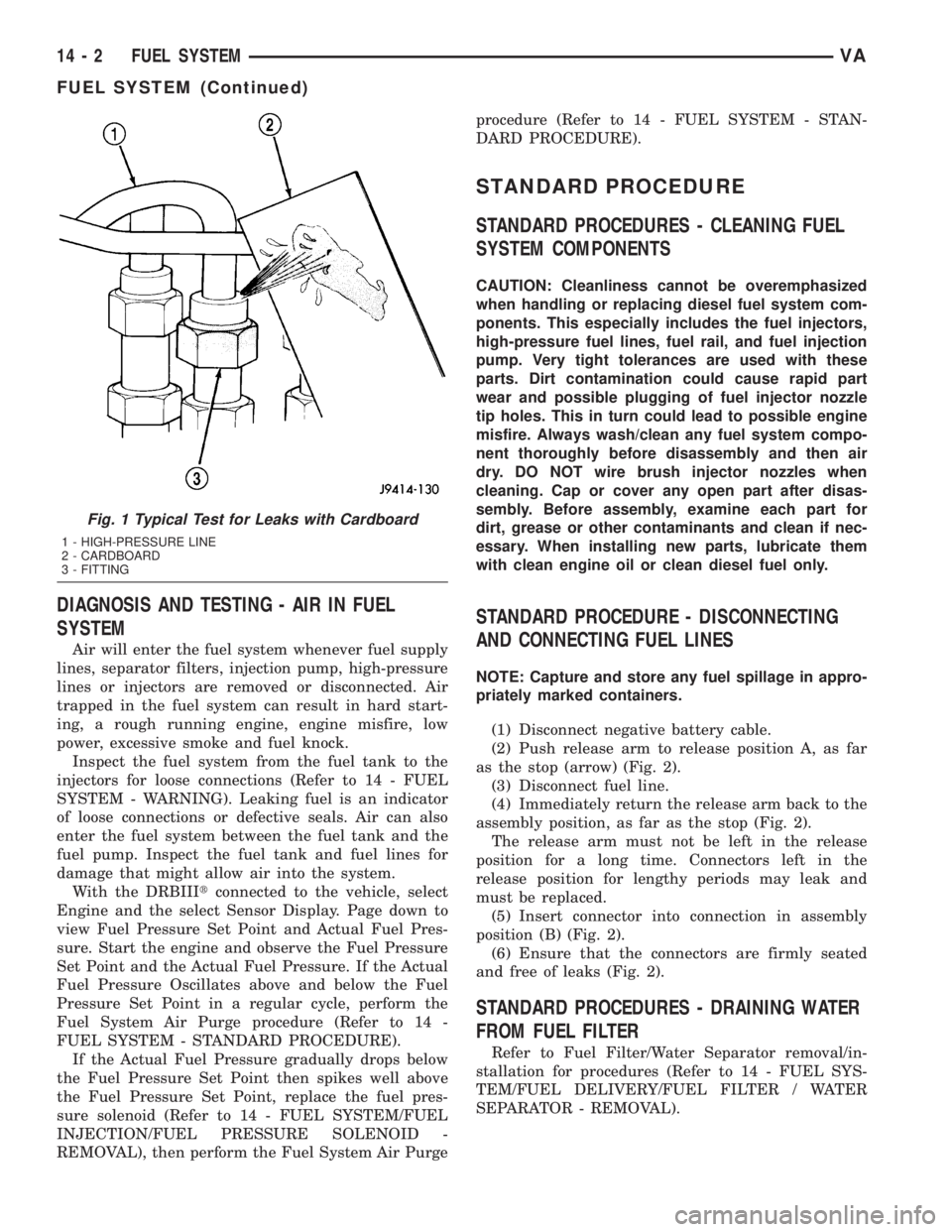
Fig. 1 Typical Test for Leaks with Cardboard
1 - HIGH-PRESSURE LINE
2 - CARDBOARD
3 - FITTING
14 - 2 FUEL SYSTEMVA
FUEL SYSTEM (Continued)
Page 1009 of 1232
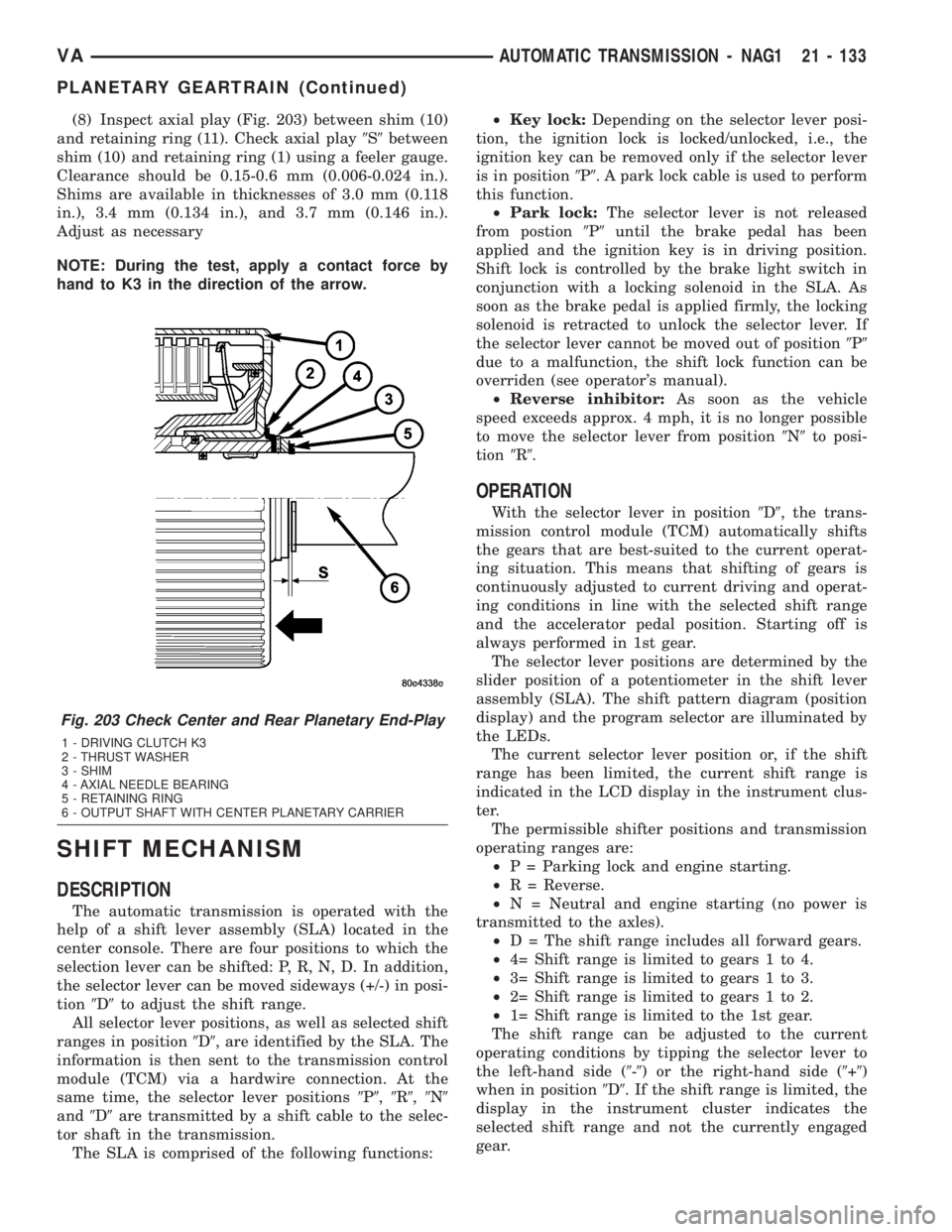
(8) Inspect axial play (Fig. 203) between shim (10)
and retaining ring (11). Check axial play9S9between
shim (10) and retaining ring (1) using a feeler gauge.
Clearance should be 0.15-0.6 mm (0.006-0.024 in.).
Shims are available in thicknesses of 3.0 mm (0.118
in.), 3.4 mm (0.134 in.), and 3.7 mm (0.146 in.).
Adjust as necessary
NOTE: During the test, apply a contact force by
hand to K3 in the direction of the arrow.
SHIFT MECHANISM
DESCRIPTION
The automatic transmission is operated with the
help of a shift lever assembly (SLA) located in the
center console. There are four positions to which the
selection lever can be shifted: P, R, N, D. In addition,
the selector lever can be moved sideways (+/-) in posi-
tion9D9to adjust the shift range.
All selector lever positions, as well as selected shift
ranges in position9D9, are identified by the SLA. The
information is then sent to the transmission control
module (TCM) via a hardwire connection. At the
same time, the selector lever positions9P9,9R9,9N9
and9D9are transmitted by a shift cable to the selec-
tor shaft in the transmission.
The SLA is comprised of the following functions:²Key lock:Depending on the selector lever posi-
tion, the ignition lock is locked/unlocked, i.e., the
ignition key can be removed only if the selector lever
is in position9P9. A park lock cable is used to perform
this function.
²Park lock:The selector lever is not released
from postion9P9until the brake pedal has been
applied and the ignition key is in driving position.
Shift lock is controlled by the brake light switch in
conjunction with a locking solenoid in the SLA. As
soon as the brake pedal is applied firmly, the locking
solenoid is retracted to unlock the selector lever. If
the selector lever cannot be moved out of position9P9
due to a malfunction, the shift lock function can be
overriden (see operator's manual).
²Reverse inhibitor:As soon as the vehicle
speed exceeds approx. 4 mph, it is no longer possible
to move the selector lever from position9N9to posi-
tion9R9.
OPERATION
With the selector lever in position9D9, the trans-
mission control module (TCM) automatically shifts
the gears that are best-suited to the current operat-
ing situation. This means that shifting of gears is
continuously adjusted to current driving and operat-
ing conditions in line with the selected shift range
and the accelerator pedal position. Starting off is
always performed in 1st gear.
The selector lever positions are determined by the
slider position of a potentiometer in the shift lever
assembly (SLA). The shift pattern diagram (position
display) and the program selector are illuminated by
the LEDs.
The current selector lever position or, if the shift
range has been limited, the current shift range is
indicated in the LCD display in the instrument clus-
ter.
The permissible shifter positions and transmission
operating ranges are:
²P = Parking lock and engine starting.
²R = Reverse.
²N = Neutral and engine starting (no power is
transmitted to the axles).
²D = The shift range includes all forward gears.
²4= Shift range is limited to gears 1 to 4.
²3= Shift range is limited to gears 1 to 3.
²2= Shift range is limited to gears 1 to 2.
²1= Shift range is limited to the 1st gear.
The shift range can be adjusted to the current
operating conditions by tipping the selector lever to
the left-hand side (9-9) or the right-hand side (9+9)
when in position9D9. If the shift range is limited, the
display in the instrument cluster indicates the
selected shift range and not the currently engaged
gear.
Fig. 203 Check Center and Rear Planetary End-Play
1 - DRIVING CLUTCH K3
2 - THRUST WASHER
3 - SHIM
4 - AXIAL NEEDLE BEARING
5 - RETAINING RING
6 - OUTPUT SHAFT WITH CENTER PLANETARY CARRIER
VAAUTOMATIC TRANSMISSION - NAG1 21 - 133
PLANETARY GEARTRAIN (Continued)
Page 1010 of 1232
Tipping the shift lever will have the following
results:
²Tipping the selector lever toward(-(one
time after another:The shift range is reduced in
descending sequence by one gear each time, i.e., from
D-4-3-2-1.Iftheselected limitation of the shift
range would result in a downshift causing excessive
engine speed, the shifting is not executed and the
engaged gear as well as the shift range remain
unchanged. This is to prevent the engine from over-
speeding. Engine retardation is low with the selector
lever in position9D9. To make use of the full braking
power of the engine,9manual9downshifting by tip-
ping the lever towards the left-hand side is recom-
mended. If this has been done, subsequent upshifting
must be carried out manually as well.
²Tipping the selector lever toward(-(and
holding it in this position:The currently engaged
gear in range9D9is indicated in the instrument clus-
ter display and the shift range is limited to this gear.
²Tipping the selector lever toward(+(one
time after another:The shift range is increased by
one gear each time and the increased shift range is
displayed in the instrument cluster; possibly, the
transmission upshifts to a faster gear.
²Tipping the selector lever toward(+(sev-
eral times:The shift range is increased by one gear
each time the lever is tipped until the shift range
ends up in9D9.
²Tipping the selector lever toward(+(and
holding it in this position:The shift range is
extended immediately to9D9, shift ranges are indi-
cated in ascending sequence; possibly, the transmis-
sion upshifts to a faster gear due to the extension of
the shift range.
REMOVAL
(1) Move selector lever to position9D9.
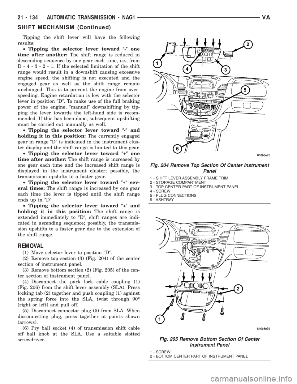
(2) Remove top section (3) (Fig. 204) of the center
section of instrument panel.
(3) Remove bottom section (2) (Fig. 205) of the cen-
ter section of instrument panel.
(4) Disconnect the park lock cable coupling (1)
(Fig. 206) from the shift lever assembly (SLA). Press
locking tab (2) together and push coupling (1) against
the spring force into the SLA, twist through 90É
(right or left) and pull off.
(5) Disconnect connector plug (5) from SLA. When
disconnecting plug, press together at points shown
(arrows).
(6) Pry ball socket (4) of transmission shift cable
off ball knob at the SLA. Use a suitable slotted
screwdriver.
Fig. 204 Remove Top Section Of Center Instrument
Panel
1 - SHIFT LEVER ASSEMBLY FRAME TRIM
2 - STORAGE COMPARTMENT
3 - TOP CENTER PART OF INSTRUMENT PANEL
4 - SCREW
5 - PLUG CONNECTIONS
6 - ASHTRAY
Fig. 205 Remove Bottom Section Of Center
Instrument Panel
1 - SCREW
2 - BOTTOM CENTER PART OF INSTRUMENT PANEL
21 - 134 AUTOMATIC TRANSMISSION - NAG1VA
SHIFT MECHANISM (Continued)