2005 MERCEDES-BENZ SPRINTER check transmission fluid
[x] Cancel search: check transmission fluidPage 978 of 1232
DIAGNOSIS AND TESTING
DIAGNOSIS AND TESTING - EFFECTS OF
INCORRECT FLUID LEVEL
A low fluid level allows the pump to take in air
along with the fluid. Air in the fluid will cause fluid
pressures to be low and develop slower than normal.
If the transmission is overfilled, the gears churn the
fluid into foam. This aerates the fluid and causing
the same conditions occurring with a low level. In
either case, air bubbles cause fluid overheating, oxi-
dation and varnish buildup which interferes with
valve and clutch operation. Foaming also causes fluid
expansion which can result in fluid overflow from the
transmission vent or fill tube. Fluid overflow can eas-
ily be mistaken for a leak if inspection is not careful.
DIAGNOSIS AND TESTING - CAUSES OF
BURNT FLUID
Burnt, discolored fluid is a result of overheating
which has three primary causes.
(1) Internal clutch slippage, usually caused by low
line pressure, inadequate clutch apply pressure, or
clutch seal failure.
(2) A result of restricted fluid flow through the
main and/or auxiliary cooler. This condition is usu-
ally the result of a faulty or improperly installed
drainback valve, a damaged main cooler, or severe
restrictions in the coolers and lines caused by debris
or kinked lines.
(3) Heavy duty operation with a vehicle not prop-
erly equipped for this type of operation. Trailer tow-
ing or similar high load operation will overheat the
transmission fluid if the vehicle is improperly
equipped. Such vehicles should have an auxiliary
transmission fluid cooler, a heavy duty cooling sys-
tem, and the engine/axle ratio combination needed to
handle heavy loads.
DIAGNOSIS AND TESTING - FLUID
CONTAMINATION
Transmission fluid contamination is generally a
result of:
²adding incorrect fluid
²failure to clean dipstick and fill tube when
checking level
²engine coolant entering the fluid
²internal failure that generates debris
²overheat that generates sludge (fluid break-
down)
²failure to replace contaminated converter after
repair
The use of non-recommended fluids can result in
transmission failure. The usual results are erratic
shifts, slippage, abnormal wear and eventual failuredue to fluid breakdown and sludge formation. Avoid
this condition by using recommended fluids only.
The dipstick cap and fill tube should be wiped
clean before checking fluid level. Dirt, grease and
other foreign material on the cap and tube could fall
into the tube if not removed beforehand. Take the
time to wipe the cap and tube clean before withdraw-
ing the dipstick.
Engine coolant in the transmission fluid is gener-
ally caused by a cooler malfunction. The only remedy
is to replace the radiator as the cooler in the radiator
is not a serviceable part. If coolant has circulated
through the transmission, an overhaul is necessary.
The torque converter should be replaced whenever
a failure generates sludge and debris. This is neces-
sary because normal converter flushing procedures
will not remove all contaminants.
STANDARD PROCEDURE
STANDARD PROCEDURE - CHECK OIL LEVEL
(1) Verify that the vehicle is parked on a level sur-
face.
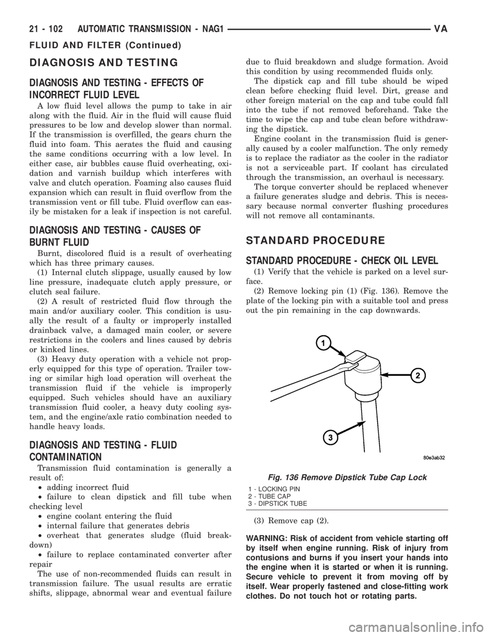
(2) Remove locking pin (1) (Fig. 136). Remove the
plate of the locking pin with a suitable tool and press
out the pin remaining in the cap downwards.
(3) Remove cap (2).
WARNING: Risk of accident from vehicle starting off
by itself when engine running. Risk of injury from
contusions and burns if you insert your hands into
the engine when it is started or when it is running.
Secure vehicle to prevent it from moving off by
itself. Wear properly fastened and close-fitting work
clothes. Do not touch hot or rotating parts.
Fig. 136 Remove Dipstick Tube Cap Lock
1 - LOCKING PIN
2 - TUBE CAP
3 - DIPSTICK TUBE
21 - 102 AUTOMATIC TRANSMISSION - NAG1VA
FLUID AND FILTER (Continued)
Page 979 of 1232
(4) Actuate the service brake. Start engine and let
it run at idle speed in selector lever position9P9.
(5) Shift through the transmission modes several
times with the vehicle stationary and the engine
idling
(6) Warm up the transmission, wait at least 2 min-
utes and check the oil level with the engine running.
Push the Oil Dipstick 8863A in up to the stop on the
electrohydraulic unit and pull out again, read off oil
level, repeat if necessary.
NOTE: The dipstick will protrude from the fill tube
approximately 75mm (3 inches) when installed.
(7) Check transmission oil temperature.
NOTE: The true transmission oil temperature can
only be read by a scan tool in REVERSE or any for-
ward gear position. (Refer to 21 - AUTOMATIC
TRANSMISSION- NAG1/TRANSMISSION TEMPERA-
TURE SENSOR/PARK-NEUTRAL SWITCH - OPERA-
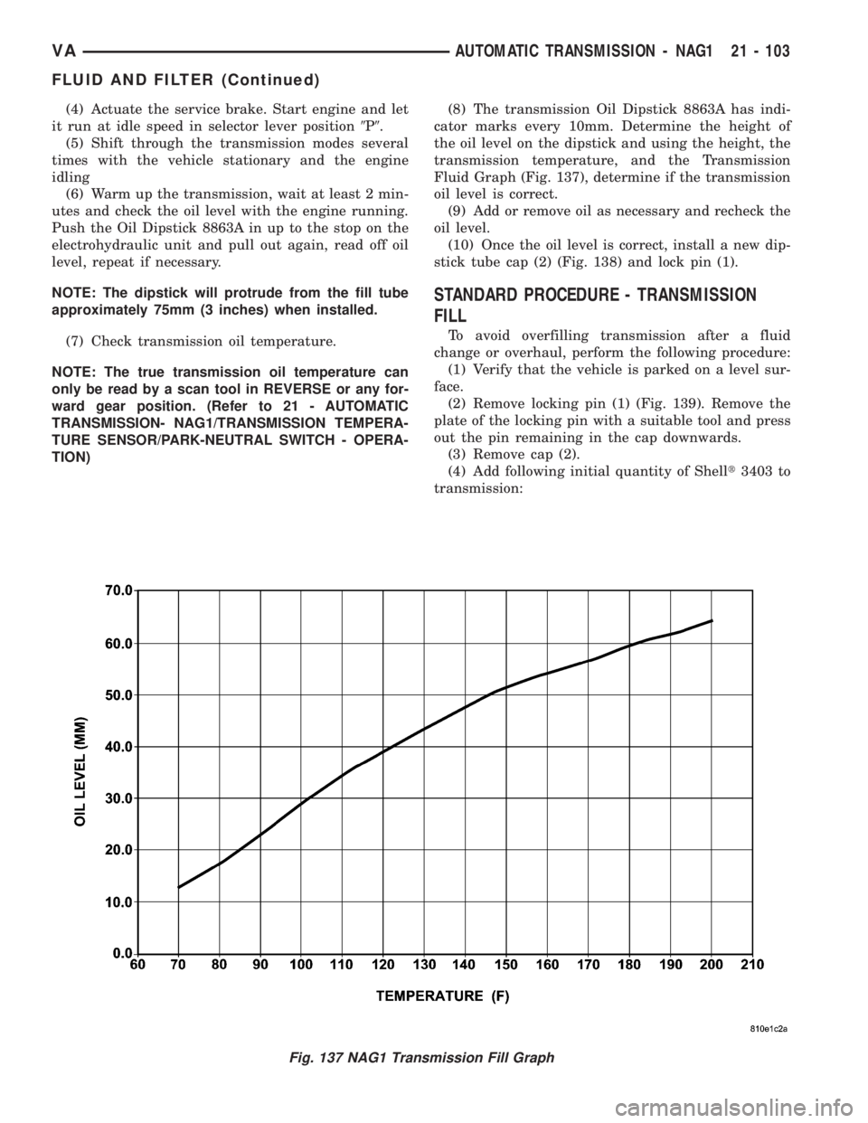
TION)(8) The transmission Oil Dipstick 8863A has indi-
cator marks every 10mm. Determine the height of
the oil level on the dipstick and using the height, the
transmission temperature, and the Transmission
Fluid Graph (Fig. 137), determine if the transmission
oil level is correct.
(9) Add or remove oil as necessary and recheck the
oil level.
(10) Once the oil level is correct, install a new dip-
stick tube cap (2) (Fig. 138) and lock pin (1).
STANDARD PROCEDURE - TRANSMISSION
FILL
To avoid overfilling transmission after a fluid
change or overhaul, perform the following procedure:
(1) Verify that the vehicle is parked on a level sur-
face.
(2) Remove locking pin (1) (Fig. 139). Remove the
plate of the locking pin with a suitable tool and press
out the pin remaining in the cap downwards.
(3) Remove cap (2).
(4) Add following initial quantity of Shellt3403 to
transmission:
Fig. 137 NAG1 Transmission Fill Graph
VAAUTOMATIC TRANSMISSION - NAG1 21 - 103
FLUID AND FILTER (Continued)
Page 980 of 1232
(a) If only fluid and filter were changed, add5.0
L (10.6 pts.)of transmission fluid to transmission.
(b) If transmission was completely overhauled,
torque converter was replaced or drained, and
cooler was flushed, add7.7 L (16.3 pts.)of trans-
mission fluid to transmission.
(5) Check the transmission fluid (Refer to 21 -
TRANSMISSION/AUTOMATIC - NAG1/FLUID -
STANDARD PROCEDURE) and adjust as required.
STANDARD PROCEDURE - FLUID/FILTER
SERVICE
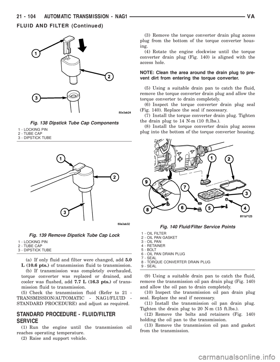
(1) Run the engine until the transmission oil
reaches operating temperature.
(2) Raise and support vehicle.(3) Remove the torque converter drain plug access
plug from the bottom of the torque converter hous-
ing.
(4) Rotate the engine clockwise until the torque
converter drain plug (Fig. 140) is aligned with the
access hole.
NOTE: Clean the area around the drain plug to pre-
vent dirt from entering the torque converter.
(5) Using a suitable drain pan to catch the fluid,
remove the torque converter drain plug and allow the
torque converter to drain completely.
(6) Inspect the torque converter drain plug seal
(Fig. 140). Replace the seal if necessary.
(7) Install the torque converter drain plug. Tighten
the drain plug to 14 N´m (10 ft.lbs.).
(8) Install the torque converter drain plug access
plug into the bottom of the torque converter housing.
(9) Using a suitable drain pan to catch the fluid,
remove the transmission oil pan drain plug (Fig. 140)
and allow the oil pan to drain completely.
(10) Inspect the transmission oil pan drain plug
seal. Replace the seal if necessary.
(11) Install the transmission oil pan drain plug.
Tighten the drain plug to 20 N´m (15 ft.lbs.).
(12) Remove the bolts and retainers (Fig. 140)
holding the oil pan to the transmission.
(13) Remove the transmission oil pan and gasket
from the transmission.
Fig. 138 Dipstick Tube Cap Components
1 - LOCKING PIN
2 - TUBE CAP
3 - DIPSTICK TUBE
Fig. 139 Remove Dipstick Tube Cap Lock
1 - LOCKING PIN
2 - TUBE CAP
3 - DIPSTICK TUBE
Fig. 140 Fluid/Filter Service Points
1 - OIL FILTER
2 - OIL PAN GASKET
3 - OIL PAN
4 - RETAINER
5 - BOLT
6 - OIL PAN DRAIN PLUG
7 - SEAL
8 - TORQUE CONVERTER DRAIN PLUG
9 - SEAL
21 - 104 AUTOMATIC TRANSMISSION - NAG1VA
FLUID AND FILTER (Continued)
Page 981 of 1232
(14) Remove the transmission oil filter and o-ring
from the electrohydraulic control unit.
(15) Clean the inside of the oil pan of any debris.
Inspect the oil pan gasket and replace if necessary.
(16) Install a new oil filter and o-ring into the elec-
trohydraulic control unit.
(17) Install the oil pan and gasket onto the trans-
mission.
(18) Install the oil pan bolts and retainers. Torque
the bolts to 8 N´m (70 in.lbs.).
(19) Lower the vehicle and add 7.0 L (7.4 qts.) of
transmission fluid to the transmission.
(20) Check the oil level (Refer to 21 - TRANSMIS-
SION/AUTOMATIC - NAG1/FLUID AND FILTER -
STANDARD PROCEDURE).
FREEWHEELING CLUTCH
DESCRIPTION
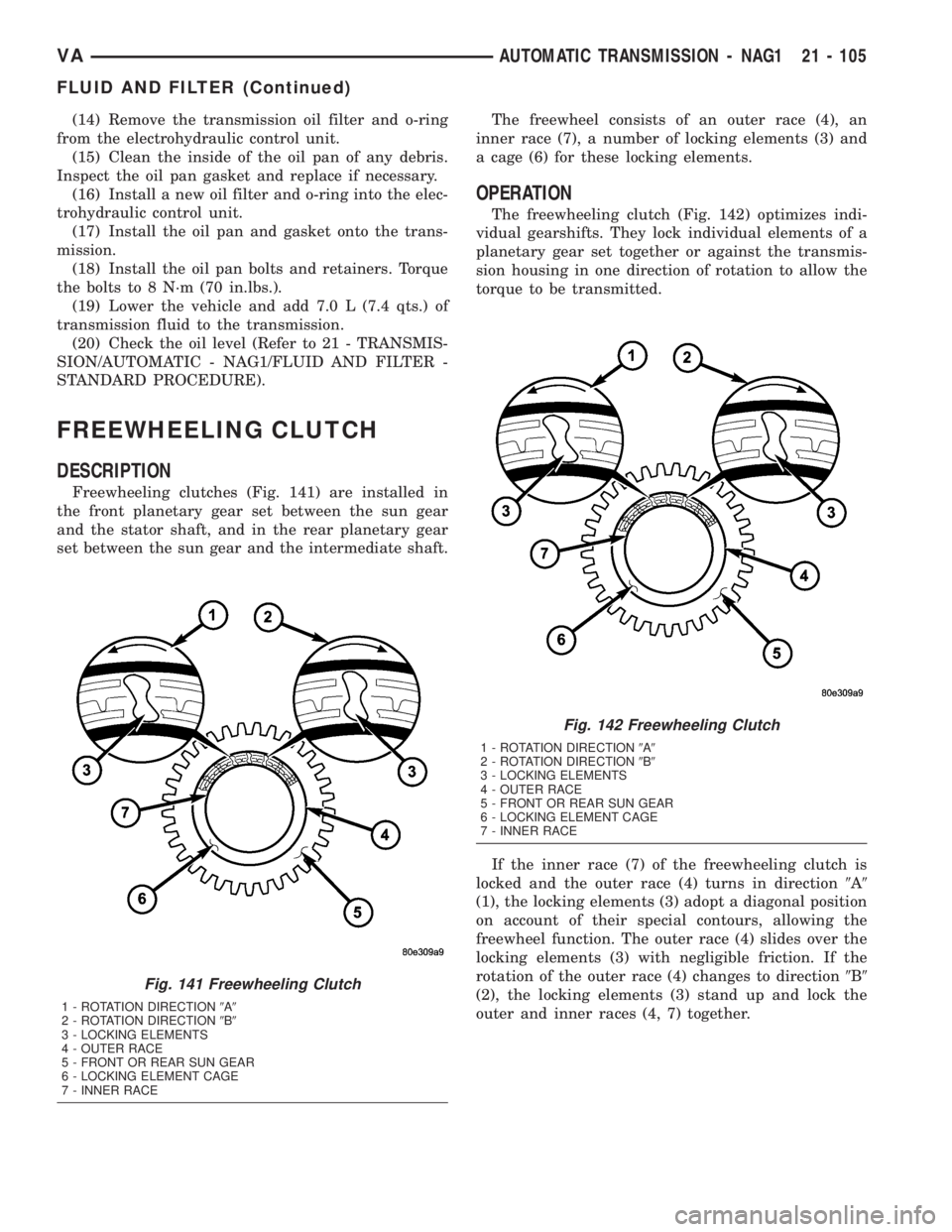
Freewheeling clutches (Fig. 141) are installed in
the front planetary gear set between the sun gear
and the stator shaft, and in the rear planetary gear
set between the sun gear and the intermediate shaft.The freewheel consists of an outer race (4), an
inner race (7), a number of locking elements (3) and
a cage (6) for these locking elements.
OPERATION
The freewheeling clutch (Fig. 142) optimizes indi-
vidual gearshifts. They lock individual elements of a
planetary gear set together or against the transmis-
sion housing in one direction of rotation to allow the
torque to be transmitted.
If the inner race (7) of the freewheeling clutch is
locked and the outer race (4) turns in direction9A9
(1), the locking elements (3) adopt a diagonal position
on account of their special contours, allowing the
freewheel function. The outer race (4) slides over the
locking elements (3) with negligible friction. If the
rotation of the outer race (4) changes to direction9B9
(2), the locking elements (3) stand up and lock the
outer and inner races (4, 7) together.
Fig. 141 Freewheeling Clutch
1 - ROTATION DIRECTION9A9
2 - ROTATION DIRECTION9B9
3 - LOCKING ELEMENTS
4 - OUTER RACE
5 - FRONT OR REAR SUN GEAR
6 - LOCKING ELEMENT CAGE
7 - INNER RACE
Fig. 142 Freewheeling Clutch
1 - ROTATION DIRECTION9A9
2 - ROTATION DIRECTION9B9
3 - LOCKING ELEMENTS
4 - OUTER RACE
5 - FRONT OR REAR SUN GEAR
6 - LOCKING ELEMENT CAGE
7 - INNER RACE
VAAUTOMATIC TRANSMISSION - NAG1 21 - 105
FLUID AND FILTER (Continued)
Page 989 of 1232
ASSEMBLY
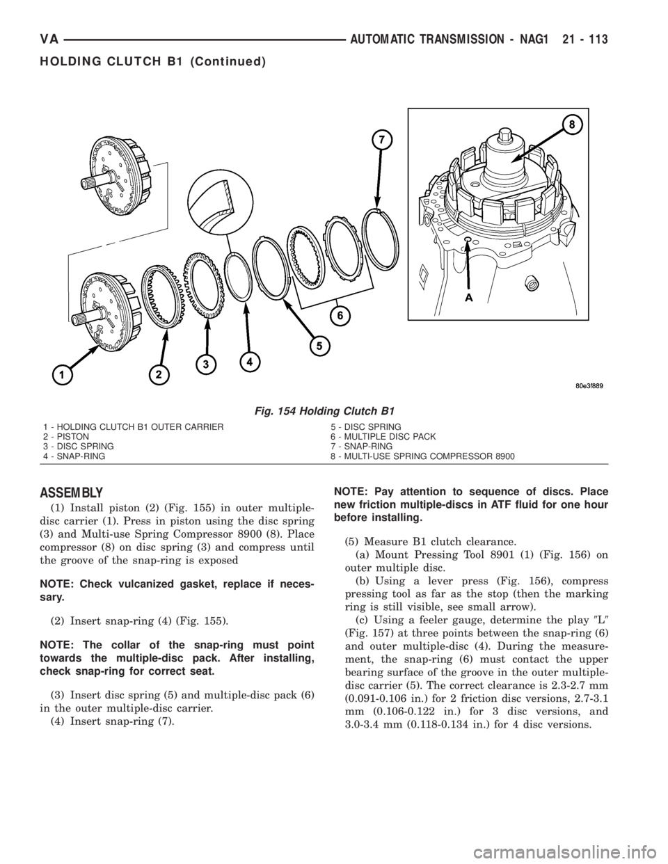
(1) Install piston (2) (Fig. 155) in outer multiple-
disc carrier (1). Press in piston using the disc spring
(3) and Multi-use Spring Compressor 8900 (8). Place
compressor (8) on disc spring (3) and compress until
the groove of the snap-ring is exposed
NOTE: Check vulcanized gasket, replace if neces-
sary.
(2) Insert snap-ring (4) (Fig. 155).
NOTE: The collar of the snap-ring must point
towards the multiple-disc pack. After installing,
check snap-ring for correct seat.
(3) Insert disc spring (5) and multiple-disc pack (6)
in the outer multiple-disc carrier.
(4) Insert snap-ring (7).NOTE: Pay attention to sequence of discs. Place
new friction multiple-discs in ATF fluid for one hour
before installing.
(5) Measure B1 clutch clearance.
(a) Mount Pressing Tool 8901 (1) (Fig. 156) on
outer multiple disc.
(b) Using a lever press (Fig. 156), compress
pressing tool as far as the stop (then the marking
ring is still visible, see small arrow).
(c) Using a feeler gauge, determine the play9L9
(Fig. 157) at three points between the snap-ring (6)
and outer multiple-disc (4). During the measure-
ment, the snap-ring (6) must contact the upper
bearing surface of the groove in the outer multiple-
disc carrier (5). The correct clearance is 2.3-2.7 mm
(0.091-0.106 in.) for 2 friction disc versions, 2.7-3.1
mm (0.106-0.122 in.) for 3 disc versions, and
3.0-3.4 mm (0.118-0.134 in.) for 4 disc versions.
Fig. 154 Holding Clutch B1
1 - HOLDING CLUTCH B1 OUTER CARRIER 5 - DISC SPRING
2 - PISTON 6 - MULTIPLE DISC PACK
3 - DISC SPRING 7 - SNAP-RING
4 - SNAP-RING 8 - MULTI-USE SPRING COMPRESSOR 8900
VAAUTOMATIC TRANSMISSION - NAG1 21 - 113
HOLDING CLUTCH B1 (Continued)
Page 992 of 1232
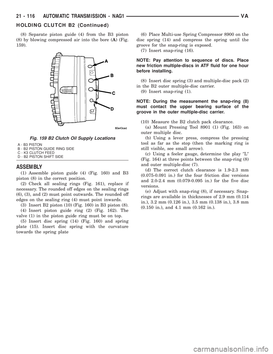
(8) Separate piston guide (4) from the B3 piston
(8) by blowing compressed air into the bore (A) (Fig.
159).
ASSEMBLY
(1) Assemble piston guide (4) (Fig. 160) and B3
piston (8) in the correct position.
(2) Check all sealing rings (Fig. 161), replace if
necessary. The rounded off edges on the sealing rings
(6), (3), and (2) must point outwards. The rounded off
edges on the sealing ring (4) must point inwards.
(3) Insert B2 piston (10) (Fig. 160) in B3 piston (8).
(4) Insert piston guide ring (2) (Fig. 162). The
valve (1) in the piston guide ring must be on top.
(5) Insert disc spring (14) (Fig. 160) and spring
plate (15). Insert disc spring with the curvature
towards the spring plate(6) Place Multi-use Spring Compressor 8900 on the
disc spring (14) and compress the spring until the
groove for the snap-ring is exposed.
(7) Insert snap-ring (16).
NOTE: Pay attention to sequence of discs. Place
new friction multiple-discs in ATF fluid for one hour
before installing.
(8) Insert disc spring (3) and multiple-disc pack (2)
in the B2 outer multiple-disc carrier.
(9) Insert snap-ring (1).
NOTE: During the measurement the snap-ring (8)
must contact the upper bearing surface of the
groove in the outer multiple-disc carrier.
(10) Measure the B2 clutch pack clearance.
(a) Mount Pressing Tool 8901 (1) (Fig. 163) on
outer multiple disc.
(b) Using a lever press, compress the pressing
tool as far as the stop (then the marking ring is
still visible, see small arrow).
(c) Using a feeler gauge, determine the play9L9
(Fig. 164) at three points between the snap-ring (8)
and outer multiple-disc (7).
(d) The correct clutch clearance is 1.9-2.3 mm
(0.075-0.091 in.) for the four friction disc versions
and 2.0-2.4 mm (0.079-0.095 in.) for the five disc
versions.
(e) Adjust with snap-ring (8), if necessary. Snap-
rings are available in thicknesses of 2.9 mm (0.114
in.), 3.2 mm (0.126 in.), 3.5 mm (0.138 in.), 3.8 mm
(0.150 in.), and 4.1 mm (0.162 in.).
Fig. 159 B2 Clutch Oil Supply Locations
A - B3 PISTON
B - B2 PISTON GUIDE RING SIDE
C - K3 CLUTCH FEED
D - B2 PISTON SHIFT SIDE
21 - 116 AUTOMATIC TRANSMISSION - NAG1VA
HOLDING CLUTCH B2 (Continued)
Page 1022 of 1232
TORQUE CONVERTER CLUTCH (TCC)
In a standard torque converter, the impeller and
turbine are rotating at about the same speed and the
stator is freewheeling, providing no torque multipli-
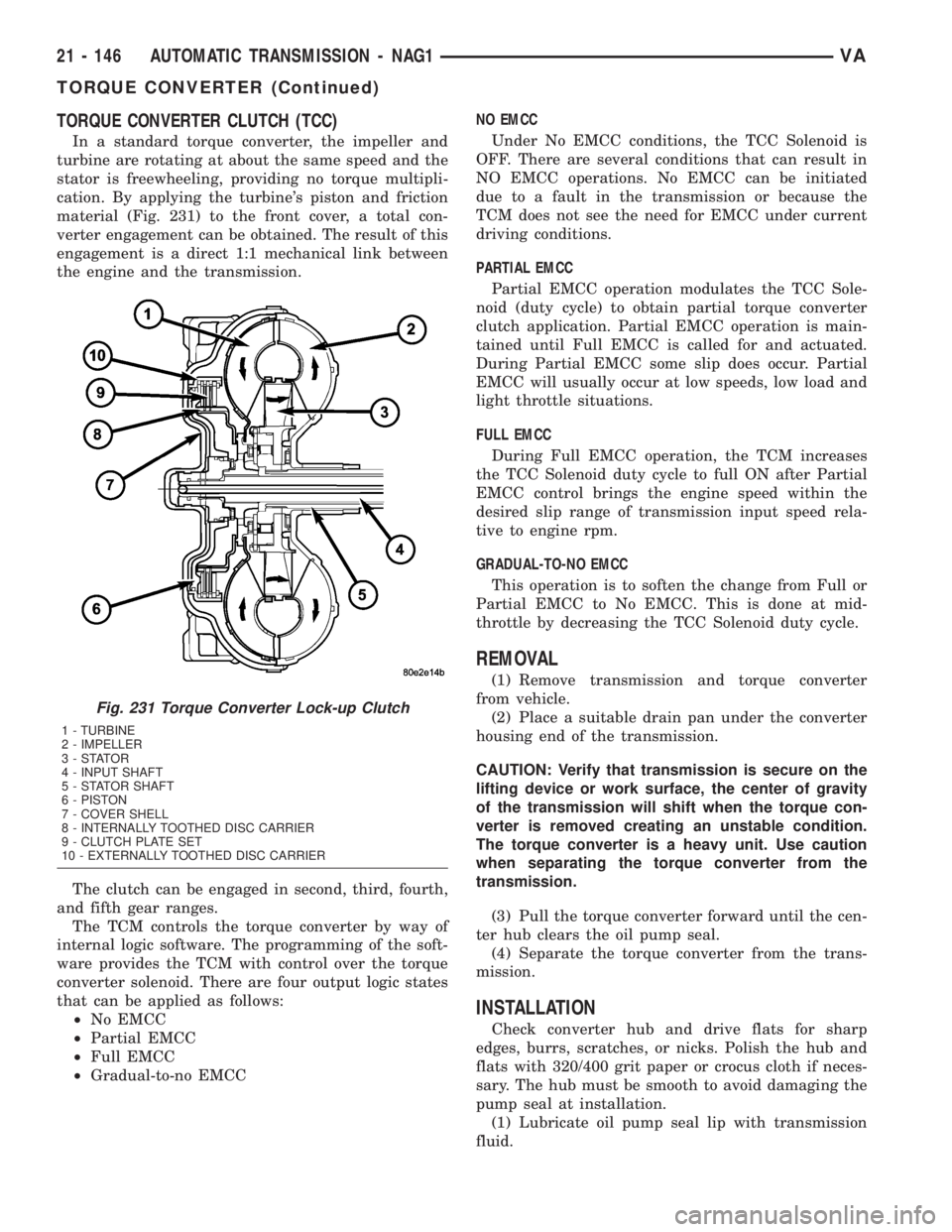
cation. By applying the turbine's piston and friction
material (Fig. 231) to the front cover, a total con-
verter engagement can be obtained. The result of this
engagement is a direct 1:1 mechanical link between
the engine and the transmission.
The clutch can be engaged in second, third, fourth,
and fifth gear ranges.
The TCM controls the torque converter by way of
internal logic software. The programming of the soft-
ware provides the TCM with control over the torque
converter solenoid. There are four output logic states
that can be applied as follows:
²No EMCC
²Partial EMCC
²Full EMCC
²Gradual-to-no EMCCNO EMCC
Under No EMCC conditions, the TCC Solenoid is
OFF. There are several conditions that can result in
NO EMCC operations. No EMCC can be initiated
due to a fault in the transmission or because the
TCM does not see the need for EMCC under current
driving conditions.
PARTIAL EMCC
Partial EMCC operation modulates the TCC Sole-
noid (duty cycle) to obtain partial torque converter
clutch application. Partial EMCC operation is main-
tained until Full EMCC is called for and actuated.
During Partial EMCC some slip does occur. Partial
EMCC will usually occur at low speeds, low load and
light throttle situations.
FULL EMCC
During Full EMCC operation, the TCM increases
the TCC Solenoid duty cycle to full ON after Partial
EMCC control brings the engine speed within the
desired slip range of transmission input speed rela-
tive to engine rpm.
GRADUAL-TO-NO EMCC
This operation is to soften the change from Full or
Partial EMCC to No EMCC. This is done at mid-
throttle by decreasing the TCC Solenoid duty cycle.
REMOVAL
(1) Remove transmission and torque converter
from vehicle.
(2) Place a suitable drain pan under the converter
housing end of the transmission.
CAUTION: Verify that transmission is secure on the
lifting device or work surface, the center of gravity
of the transmission will shift when the torque con-
verter is removed creating an unstable condition.
The torque converter is a heavy unit. Use caution
when separating the torque converter from the
transmission.
(3) Pull the torque converter forward until the cen-
ter hub clears the oil pump seal.
(4) Separate the torque converter from the trans-
mission.
INSTALLATION
Check converter hub and drive flats for sharp
edges, burrs, scratches, or nicks. Polish the hub and
flats with 320/400 grit paper or crocus cloth if neces-
sary. The hub must be smooth to avoid damaging the
pump seal at installation.
(1) Lubricate oil pump seal lip with transmission
fluid.
Fig. 231 Torque Converter Lock-up Clutch
1 - TURBINE
2 - IMPELLER
3-STATOR
4 - INPUT SHAFT
5 - STATOR SHAFT
6 - PISTON
7 - COVER SHELL
8 - INTERNALLY TOOTHED DISC CARRIER
9 - CLUTCH PLATE SET
10 - EXTERNALLY TOOTHED DISC CARRIER
21 - 146 AUTOMATIC TRANSMISSION - NAG1VA
TORQUE CONVERTER (Continued)
Page 1023 of 1232
(2) Place torque converter in position on transmis-
sion.
CAUTION: Do not damage oil pump seal or con-
verter hub while inserting torque converter into the
front of the transmission.
(3) Align torque converter to oil pump seal open-
ing.
(4) Insert torque converter hub into oil pump.
(5) While pushing torque converter inward, rotate
converter until converter is fully seated in the oil
pump gears.
(6) Check converter seating with a scale and
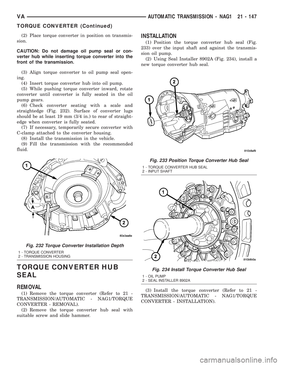
straightedge (Fig. 232). Surface of converter lugs
should be at least 19 mm (3/4 in.) to rear of straight-
edge when converter is fully seated.
(7) If necessary, temporarily secure converter with
C-clamp attached to the converter housing.
(8) Install the transmission in the vehicle.
(9) Fill the transmission with the recommended
fluid.
TORQUE CONVERTER HUB
SEAL
REMOVAL
(1) Remove the torque converter (Refer to 21 -
TRANSMISSION/AUTOMATIC - NAG1/TORQUE
CONVERTER - REMOVAL).
(2) Remove the torque converter hub seal with
suitable screw and slide hammer.
INSTALLATION
(1) Position the torque converter hub seal (Fig.
233) over the input shaft and against the transmis-
sion oil pump.
(2) Using Seal Installer 8902A (Fig. 234), install a
new torque converter hub seal.
(3) Install the torque converter (Refer to 21 -
TRANSMISSION/AUTOMATIC - NAG1/TORQUE
CONVERTER - INSTALLATION).
Fig. 232 Torque Converter Installation Depth
1 - TORQUE CONVERTER
2 - TRANSMISSION HOUSING
Fig. 233 Position Torque Converter Hub Seal
1 - TORQUE CONVERTER HUB SEAL
2 - INPUT SHAFT
Fig. 234 Install Torque Converter Hub Seal
1 - OIL PUMP
2 - SEAL INSTALLER 8902A
VAAUTOMATIC TRANSMISSION - NAG1 21 - 147
TORQUE CONVERTER (Continued)