2005 MERCEDES-BENZ SPRINTER Clutch fan
[x] Cancel search: Clutch fanPage 98 of 1232
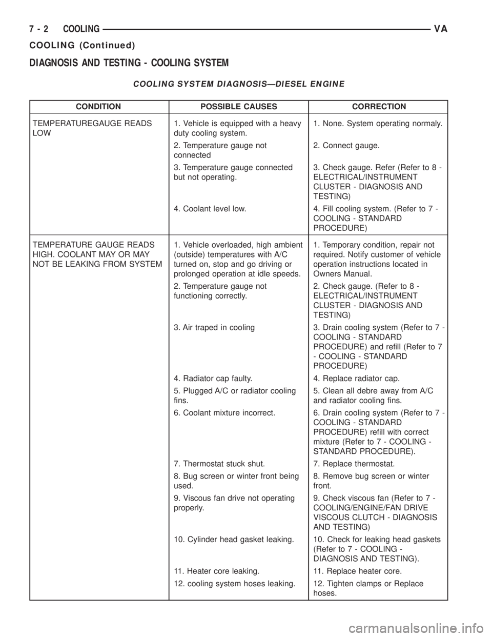
DIAGNOSIS AND TESTING - COOLING SYSTEM
COOLING SYSTEM DIAGNOSISÐDIESEL ENGINE
CONDITION POSSIBLE CAUSES CORRECTION
TEMPERATUREGAUGE READS
LOW1. Vehicle is equipped with a heavy
duty cooling system.1. None. System operating normaly.
2. Temperature gauge not
connected2. Connect gauge.
3. Temperature gauge connected
but not operating.3. Check gauge. Refer (Refer to 8 -
ELECTRICAL/INSTRUMENT
CLUSTER - DIAGNOSIS AND
TESTING)
4. Coolant level low. 4. Fill cooling system. (Refer to 7 -
COOLING - STANDARD
PROCEDURE)
TEMPERATURE GAUGE READS
HIGH. COOLANT MAY OR MAY
NOT BE LEAKING FROM SYSTEM1. Vehicle overloaded, high ambient
(outside) temperatures with A/C
turned on, stop and go driving or
prolonged operation at idle speeds.1. Temporary condition, repair not
required. Notify customer of vehicle
operation instructions located in
Owners Manual.
2. Temperature gauge not
functioning correctly.2. Check gauge. (Refer to 8 -
ELECTRICAL/INSTRUMENT
CLUSTER - DIAGNOSIS AND
TESTING)
3. Air traped in cooling 3. Drain cooling system (Refer to 7 -
COOLING - STANDARD
PROCEDURE) and refill (Refer to 7
- COOLING - STANDARD
PROCEDURE)
4. Radiator cap faulty. 4. Replace radiator cap.
5. Plugged A/C or radiator cooling
fins.5. Clean all debre away from A/C
and radiator cooling fins.
6. Coolant mixture incorrect. 6. Drain cooling system (Refer to 7 -
COOLING - STANDARD
PROCEDURE) refill with correct
mixture (Refer to 7 - COOLING -
STANDARD PROCEDURE).
7. Thermostat stuck shut. 7. Replace thermostat.
8. Bug screen or winter front being
used.8. Remove bug screen or winter
front.
9. Viscous fan drive not operating
properly.9. Check viscous fan (Refer to 7 -
COOLING/ENGINE/FAN DRIVE
VISCOUS CLUTCH - DIAGNOSIS
AND TESTING)
10. Cylinder head gasket leaking. 10. Check for leaking head gaskets
(Refer to 7 - COOLING -
DIAGNOSIS AND TESTING).
11. Heater core leaking. 11. Replace heater core.
12. cooling system hoses leaking. 12. Tighten clamps or Replace
hoses.
7 - 2 COOLINGVA
COOLING (Continued)
Page 100 of 1232
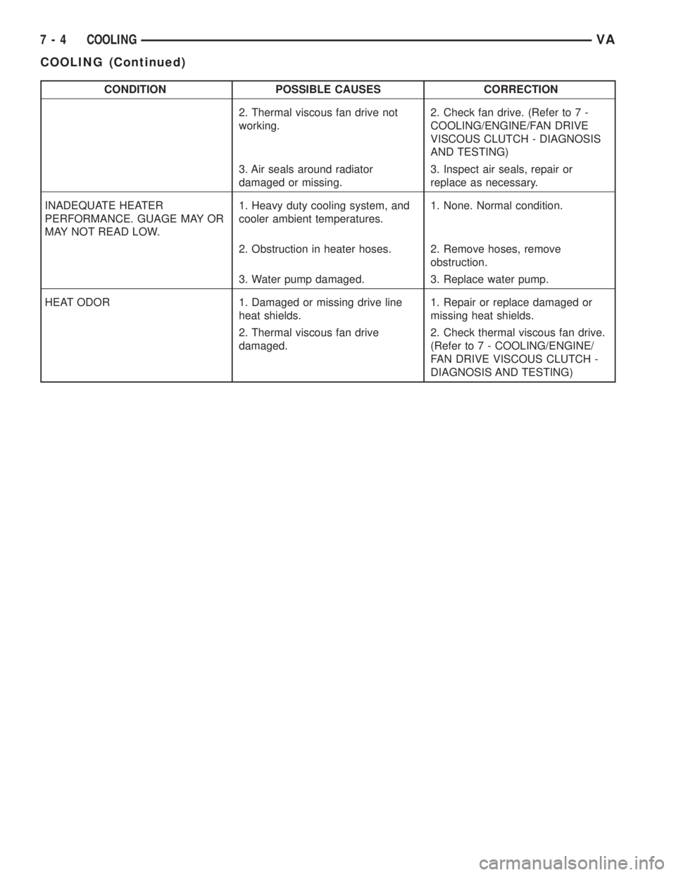
CONDITION POSSIBLE CAUSES CORRECTION
2. Thermal viscous fan drive not
working.2. Check fan drive. (Refer to 7 -
COOLING/ENGINE/FAN DRIVE
VISCOUS CLUTCH - DIAGNOSIS
AND TESTING)
3. Air seals around radiator
damaged or missing.3. Inspect air seals, repair or
replace as necessary.
INADEQUATE HEATER
PERFORMANCE. GUAGE MAY OR
MAY NOT READ LOW.1. Heavy duty cooling system, and
cooler ambient temperatures.1. None. Normal condition.
2. Obstruction in heater hoses. 2. Remove hoses, remove
obstruction.
3. Water pump damaged. 3. Replace water pump.
HEAT ODOR 1. Damaged or missing drive line
heat shields.1. Repair or replace damaged or
missing heat shields.
2. Thermal viscous fan drive
damaged.2. Check thermal viscous fan drive.
(Refer to 7 - COOLING/ENGINE/
FAN DRIVE VISCOUS CLUTCH -
DIAGNOSIS AND TESTING)
7 - 4 COOLINGVA
COOLING (Continued)
Page 105 of 1232
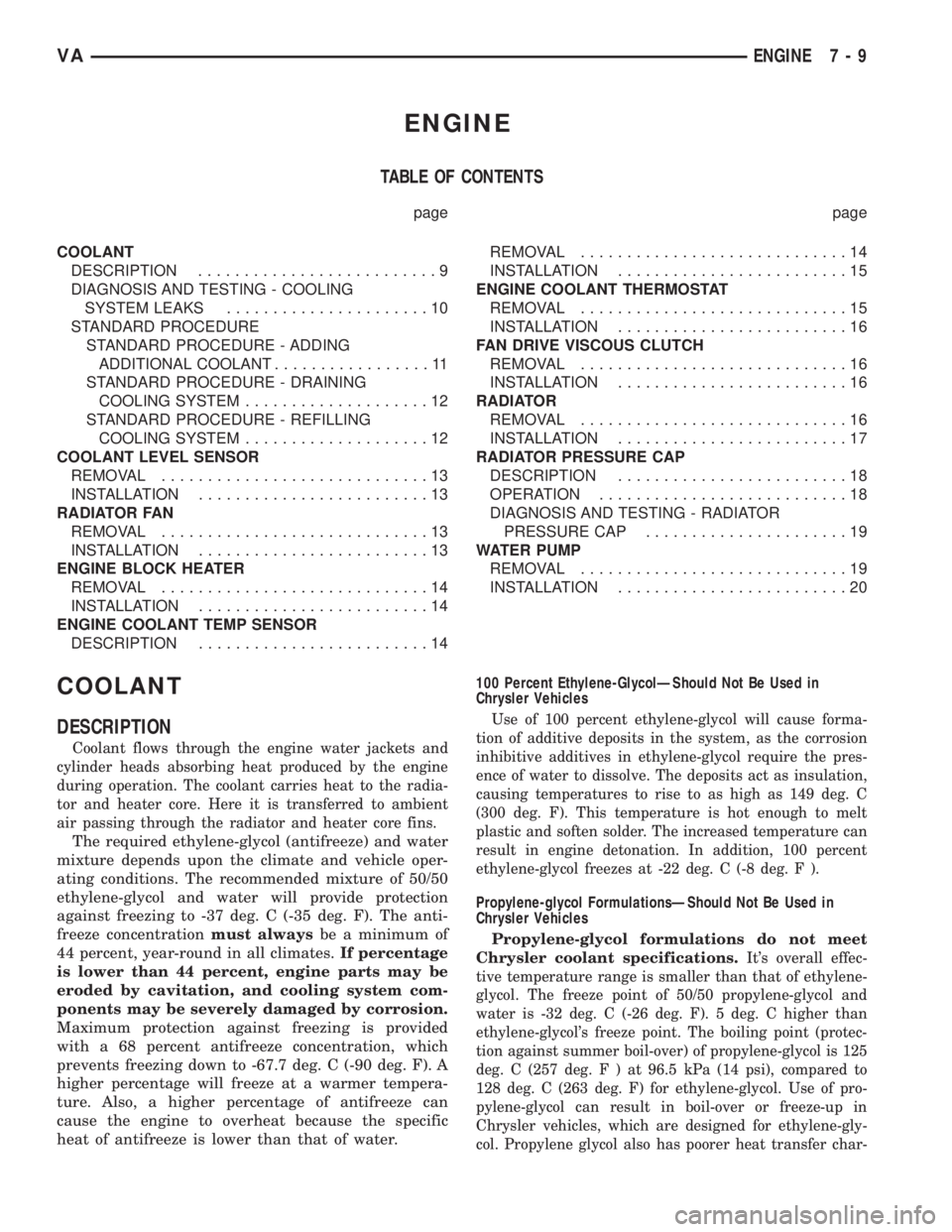
ENGINE
TABLE OF CONTENTS
page page
COOLANT
DESCRIPTION..........................9
DIAGNOSIS AND TESTING - COOLING
SYSTEM LEAKS......................10
STANDARD PROCEDURE
STANDARD PROCEDURE - ADDING
ADDITIONAL COOLANT.................11
STANDARD PROCEDURE - DRAINING
COOLING SYSTEM....................12
STANDARD PROCEDURE - REFILLING
COOLING SYSTEM....................12
COOLANT LEVEL SENSOR
REMOVAL.............................13
INSTALLATION.........................13
RADIATOR FAN
REMOVAL.............................13
INSTALLATION.........................13
ENGINE BLOCK HEATER
REMOVAL.............................14
INSTALLATION.........................14
ENGINE COOLANT TEMP SENSOR
DESCRIPTION.........................14REMOVAL.............................14
INSTALLATION.........................15
ENGINE COOLANT THERMOSTAT
REMOVAL.............................15
INSTALLATION.........................16
FAN DRIVE VISCOUS CLUTCH
REMOVAL.............................16
INSTALLATION.........................16
RADIATOR
REMOVAL.............................16
INSTALLATION.........................17
RADIATOR PRESSURE CAP
DESCRIPTION.........................18
OPERATION...........................18
DIAGNOSIS AND TESTING - RADIATOR
PRESSURE CAP......................19
WATER PUMP
REMOVAL.............................19
INSTALLATION.........................20
COOLANT
DESCRIPTION
Coolant flows through the engine water jackets and
cylinder heads absorbing heat produced by the engine
during operation. The coolant carries heat to the radia-
tor and heater core. Here it is transferred to ambient
air passing through the radiator and heater core fins.
The required ethylene-glycol (antifreeze) and water
mixture depends upon the climate and vehicle oper-
ating conditions. The recommended mixture of 50/50
ethylene-glycol and water will provide protection
against freezing to -37 deg. C (-35 deg. F). The anti-
freeze concentrationmust alwaysbe a minimum of
44 percent, year-round in all climates.If percentage
is lower than 44 percent, engine parts may be
eroded by cavitation, and cooling system com-
ponents may be severely damaged by corrosion.
Maximum protection against freezing is provided
with a 68 percent antifreeze concentration, which
prevents freezing down to -67.7 deg. C (-90 deg. F). A
higher percentage will freeze at a warmer tempera-
ture. Also, a higher percentage of antifreeze can
cause the engine to overheat because the specific
heat of antifreeze is lower than that of water.100 Percent Ethylene-GlycolÐShould Not Be Used in
Chrysler Vehicles
Use of 100 percent ethylene-glycol will cause forma-
tion of additive deposits in the system, as the corrosion
inhibitive additives in ethylene-glycol require the pres-
ence of water to dissolve. The deposits act as insulation,
causing temperatures to rise to as high as 149 deg. C
(300 deg. F). This temperature is hot enough to melt
plastic and soften solder. The increased temperature can
result in engine detonation. In addition, 100 percent
ethylene-glycol freezes at -22 deg. C (-8 deg. F ).
Propylene-glycol FormulationsÐShould Not Be Used in
Chrysler Vehicles
Propylene-glycol formulations do not meet
Chrysler coolant specifications.
It's overall effec-
tive temperature range is smaller than that of ethylene-
glycol. The freeze point of 50/50 propylene-glycol and
water is -32 deg. C (-26 deg. F). 5 deg. C higher than
ethylene-glycol's freeze point. The boiling point (protec-
tion against summer boil-over) of propylene-glycol is 125
deg. C (257 deg.F)at96.5 kPa (14 psi), compared to
128 deg. C (263 deg. F) for ethylene-glycol. Use of pro-
pylene-glycol can result in boil-over or freeze-up in
Chrysler vehicles, which are designed for ethylene-gly-
col. Propylene glycol also has poorer heat transfer char-
VAENGINE 7 - 9
Page 109 of 1232
COOLANT LEVEL SENSOR
REMOVAL
WARNING: RISK OF INJURY TO SKIN AND EYES
DUE TO SCALDING FROM HOT COOLANT. DO NOT
OPEN THE COOLING SYSTEM UNLESS THE TEM-
PERATURE IS BELOW 194ÉF (90ÉC). WEAR PRO-
TECTIVE CLOTHING AND EYE WEAR. RISK OF
POISONING IF COOLANT IS SWALLOWED. STORE
COOLANT IN PROPER AND APPROPRIATELY
MARKED CONTAINERS.
NOTE: Drain coolant from radiator drain plug only.
(1) Drain coolant until the coolant reservoir is
emptied.
(2) Disconnect the wiring harness electrical con-
nector.
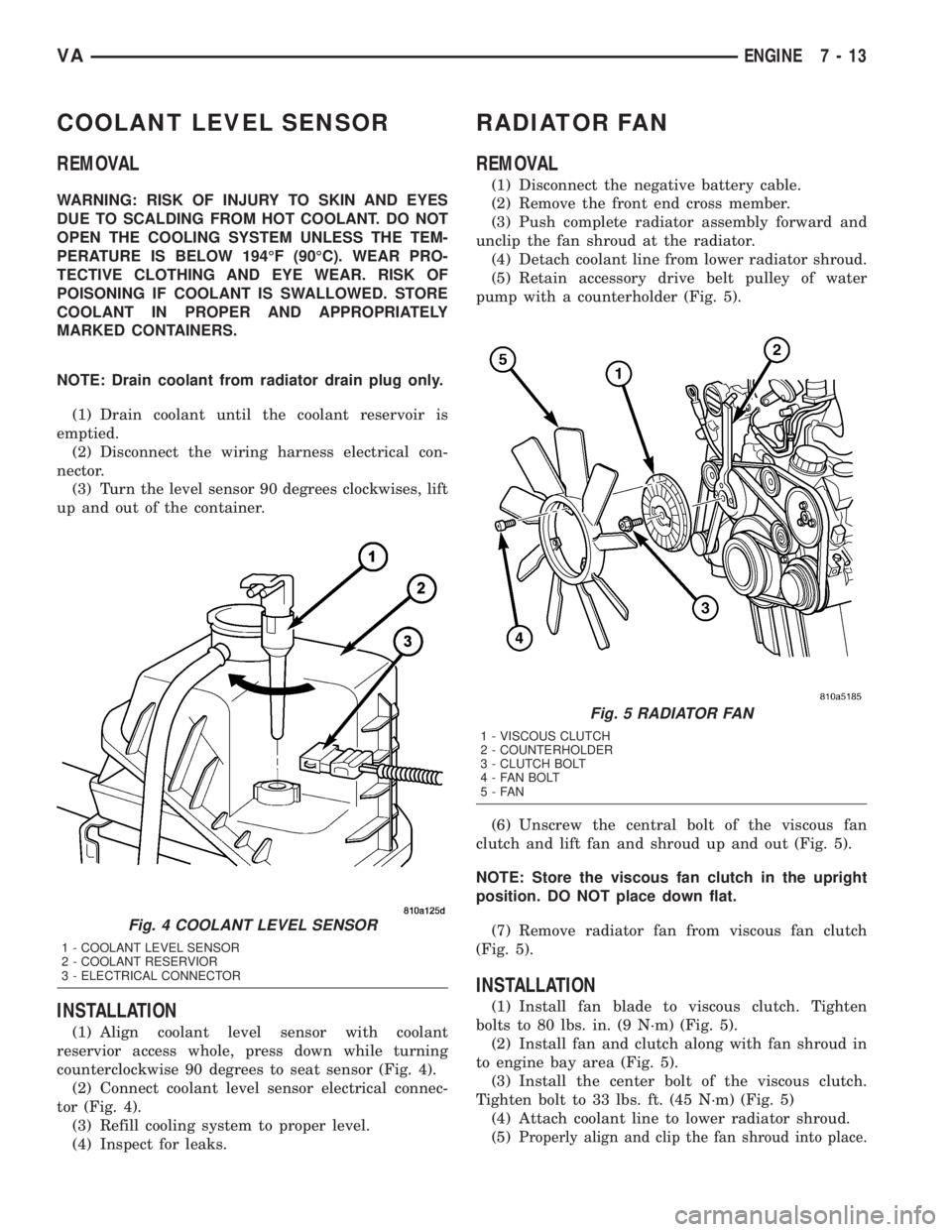
(3) Turn the level sensor 90 degrees clockwises, lift
up and out of the container.
INSTALLATION
(1) Align coolant level sensor with coolant
reservior access whole, press down while turning
counterclockwise 90 degrees to seat sensor (Fig. 4).
(2) Connect coolant level sensor electrical connec-
tor (Fig. 4).
(3) Refill cooling system to proper level.
(4) Inspect for leaks.
RADIATOR FAN
REMOVAL
(1) Disconnect the negative battery cable.
(2) Remove the front end cross member.
(3) Push complete radiator assembly forward and
unclip the fan shroud at the radiator.
(4) Detach coolant line from lower radiator shroud.
(5) Retain accessory drive belt pulley of water
pump with a counterholder (Fig. 5).
(6) Unscrew the central bolt of the viscous fan
clutch and lift fan and shroud up and out (Fig. 5).
NOTE: Store the viscous fan clutch in the upright
position. DO NOT place down flat.
(7) Remove radiator fan from viscous fan clutch
(Fig. 5).
INSTALLATION
(1) Install fan blade to viscous clutch. Tighten
bolts to 80 lbs. in. (9 N´m) (Fig. 5).
(2) Install fan and clutch along with fan shroud in
to engine bay area (Fig. 5).
(3) Install the center bolt of the viscous clutch.
Tighten bolt to 33 lbs. ft. (45 N´m) (Fig. 5)
(4) Attach coolant line to lower radiator shroud.
(5)
Properly align and clip the fan shroud into place.
Fig. 4 COOLANT LEVEL SENSOR
1 - COOLANT LEVEL SENSOR
2 - COOLANT RESERVIOR
3 - ELECTRICAL CONNECTOR
Fig. 5 RADIATOR FAN
1 - VISCOUS CLUTCH
2 - COUNTERHOLDER
3 - CLUTCH BOLT
4 - FAN BOLT
5-FAN
VAENGINE 7 - 13
Page 112 of 1232
INSTALLATION
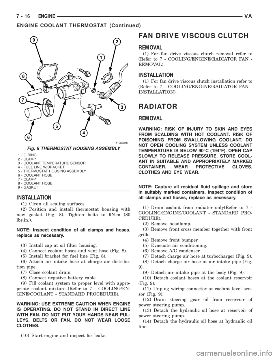
(1) Clean all sealing surfaces.
(2) Position and install thermostat housing with
new gasket (Fig. 8). Tighten bolts to 9N´m (80
lbs.in.).
NOTE: Inspect condition of all clamps and hoses,
replace as necessary.
(3) Install cap at oil filter housing.
(4) Connect coolant hoses and vent hose (Fig. 8).
(5) Install bracket for fuel line (Fig. 8).
(6) Attach air intake hose at charge air distribu-
tion pipe.
(7) Close coolant drain.
(8) Connect negative battery cable.
(9) Fill coolant system to proper level with appro-
priate coolant mixture (Refer to 7 - COOLING/EN-
GINE/COOLANT - STANDARD PROCEDURE).
WARNING: USE EXTREME CAUTION WHEN ENGINE
IS OPERATING. DO NOT STAND IN DIRECT LINE
WITH FAN. DO NOT PUT YOUR HANDS NEAR PUL-
LEYS, BELTS OR FAN. DO NOT WEAR LOOSE
CLOTHES.
(10) Start engine and inspect for leaks.
FAN DRIVE VISCOUS CLUTCH
REMOVAL
(1) For fan drive viscous clutch removal refer to
(Refer to 7 - COOLING/ENGINE/RADIATOR FAN -
REMOVAL).
INSTALLATION
(1) For fan drive viscous clutch installation refer to
(Refer to 7 - COOLING/ENGINE/RADIATOR FAN -
INSTALLATION).
RADIATOR
REMOVAL
WARNING: RISK OF INJURY TO SKIN AND EYES
FROM SCALDING WITH HOT COOLANT. RISK OF
POISONING FROM SWALLOWING COOLANT. DO
NOT OPEN COOLING SYSTEM UNLESS COOLANT
TEMPERATURE IS BELOW 90ÉC (194ÉF). OPEN CAP
SLOWLY TO RELEASE PRESSURE. STORE COOL-
ANT IN SUITABLE AND APPROPRIATELY MARKED
CONTAINER. WEAR PROTECTIVE GLOVES,
CLOTHES AND EYE WEAR.
NOTE: Capture all residual fluid spillage and store
in suitably marked containers. Inspect condition of
all clamps and hoses, replace as necessary.
(1) Drain coolant from radiator only(Refer to 7 -
COOLING/ENGINE/COOLANT - STANDARD PRO-
CEDURE).
(2) Remove headlamp.
(3) Remove front cross member together with front
grille.
(4) Remove front bumper.
(5) Evacuate air conditioning.
(6) Remove A/C condenser.
(7) Detach charge air hose at turbocharger (Fig. 9).
(8) Detach charge air hose at air intake pipe (Fig.
9).
(9) Detach air intake pipe at the body (Fig. 9).
(10) Detach coolant hoses at the coolant reservoir
(Fig. 9).
(11) Unplug wiring connector at coolant level sen-
sor (Fig. 9).
(12) Drain steering gear oil from reservoir of
power steering pump.
(13) Detach the hydraulic oil hose at reservoir of
power steering pump.
(14) Detach the hydraulic oil hose at hydraulic oil
line.
Fig. 8 THERMOSTAT HOUSING ASSEMBLY
1 - O-RING
2 - CLAMP
3 - COOLANT TEMPERATURE SENSOR
4 - FUEL LINE W/BRACKET
5 - THERMOSTAT HOUSING ASSEMBLY
6 - COOLANT HOSE
7 - CLAMP
8 - COOLANT HOSE
9 - GASKET
7 - 16 ENGINEVA
ENGINE COOLANT THERMOSTAT (Continued)
Page 115 of 1232
DIAGNOSIS AND TESTING - RADIATOR
PRESSURE CAP
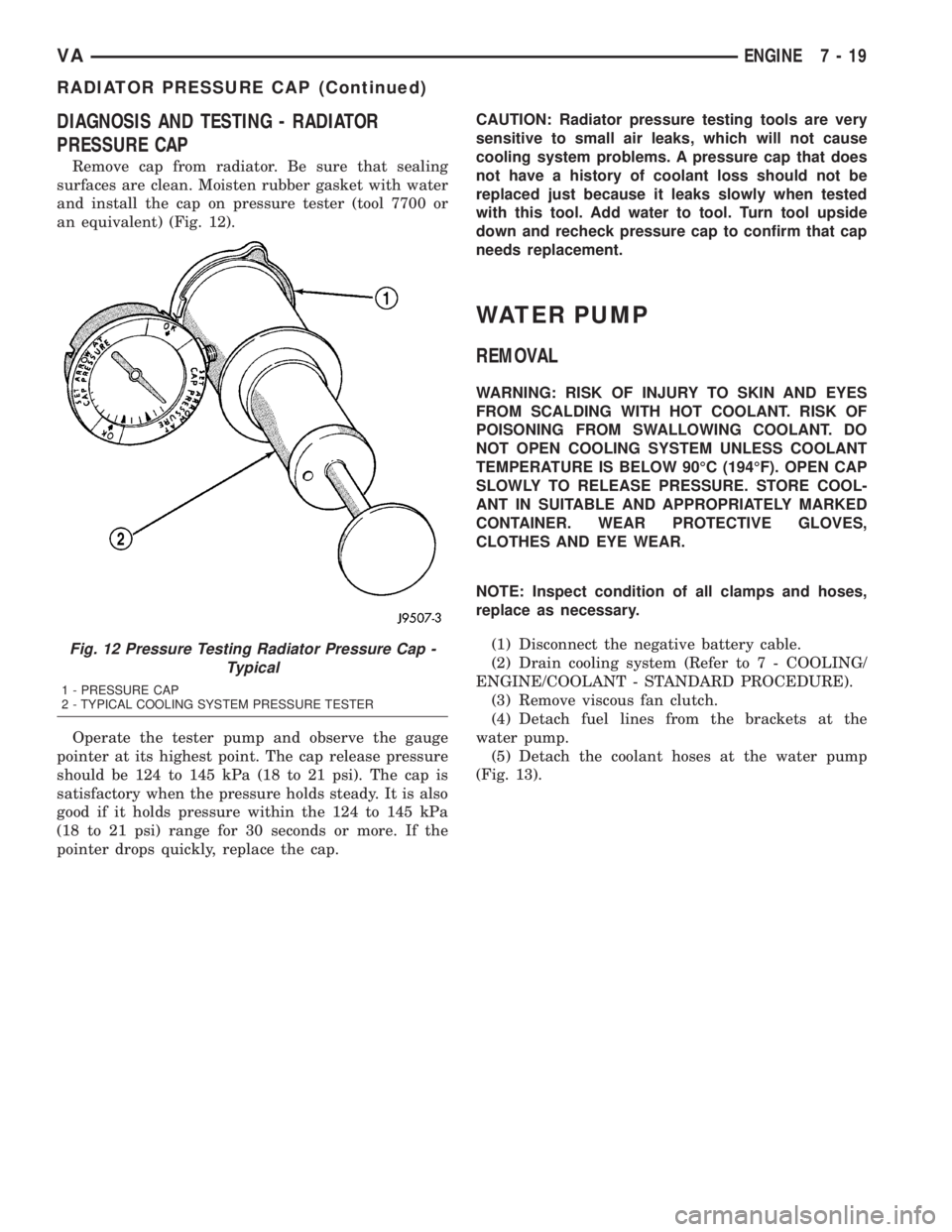
Remove cap from radiator. Be sure that sealing
surfaces are clean. Moisten rubber gasket with water
and install the cap on pressure tester (tool 7700 or
an equivalent) (Fig. 12).
Operate the tester pump and observe the gauge
pointer at its highest point. The cap release pressure
should be 124 to 145 kPa (18 to 21 psi). The cap is
satisfactory when the pressure holds steady. It is also
good if it holds pressure within the 124 to 145 kPa
(18 to 21 psi) range for 30 seconds or more. If the
pointer drops quickly, replace the cap.CAUTION: Radiator pressure testing tools are very
sensitive to small air leaks, which will not cause
cooling system problems. A pressure cap that does
not have a history of coolant loss should not be
replaced just because it leaks slowly when tested
with this tool. Add water to tool. Turn tool upside
down and recheck pressure cap to confirm that cap
needs replacement.
WATER PUMP
REMOVAL
WARNING: RISK OF INJURY TO SKIN AND EYES
FROM SCALDING WITH HOT COOLANT. RISK OF
POISONING FROM SWALLOWING COOLANT. DO
NOT OPEN COOLING SYSTEM UNLESS COOLANT
TEMPERATURE IS BELOW 90ÉC (194ÉF). OPEN CAP
SLOWLY TO RELEASE PRESSURE. STORE COOL-
ANT IN SUITABLE AND APPROPRIATELY MARKED
CONTAINER. WEAR PROTECTIVE GLOVES,
CLOTHES AND EYE WEAR.
NOTE: Inspect condition of all clamps and hoses,
replace as necessary.
(1) Disconnect the negative battery cable.
(2) Drain cooling system (Refer to 7 - COOLING/
ENGINE/COOLANT - STANDARD PROCEDURE).
(3) Remove viscous fan clutch.
(4) Detach fuel lines from the brackets at the
water pump.
(5) Detach the coolant hoses at the water pump
(Fig. 13).
Fig. 12 Pressure Testing Radiator Pressure Cap -
Typical
1 - PRESSURE CAP
2 - TYPICAL COOLING SYSTEM PRESSURE TESTER
VAENGINE 7 - 19
RADIATOR PRESSURE CAP (Continued)
Page 116 of 1232
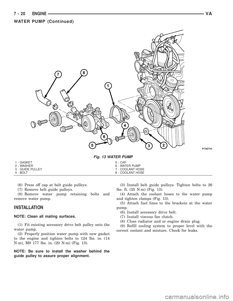
(6) Press off cap at belt guide pulleys.
(7) Remove belt guide pulleys.
(8) Remove water pump retaining bolts and
remove water pump.
INSTALLATION
NOTE: Clean all mating surfaces.
(1) Fit existing accessory drive belt pulley onto the
water pump.
(2) Properly position water pump with new gasket
to the engine and tighten bolts to 124 lbs. in. (14
N´m), M8 177 lbs. in. (20 N´m) (Fig. 13).
NOTE: Be sure to install the washer behind the
guide pulley to assure proper alignment.(3) Install belt guide pulleys. Tighten bolts to 26
lbs. ft. (35 N´m) (Fig. 13).
(4) Attach the coolant hoses to the water pump
and tighten clamps (Fig. 13).
(5) Attach fuel lines to the brackets at the water
pump.
(6) Install accessory drive belt.
(7) Install viscous fan clutch.
(8) Close radiator and or engine drain plug.
(9) Refill cooling system to proper level with the
correct coolant and mixture. Check for leaks.
Fig. 13 WATER PUMP
1 - GASKET 5 - CAP
2 - WASHER 6 - WATER PUMP
3 - GUIDE PULLEY 7 - COOLANT HOSE
4 - BOLT 8 - COOLANT HOSE
7 - 20 ENGINEVA
WATER PUMP (Continued)
Page 317 of 1232
8W-02 COMPONENT INDEX
Component Page
A/C Auxiliary Fan Relay................ 8W-42
A/C Auxiliary Fan..................... 8W-42
A/C Compressor Clutch................. 8W-42
A/C Control Module-Roof................ 8W-42
A/C Fan Switch....................... 8W-42
A/C Switch-Roof...................... 8W-42
Accelerator Pedal Position Sensor......... 8W-30
Air Outlet Temperature Sensor........... 8W-42
Airbag Control Module................. 8W-43
Airbag Squibs........................ 8W-43
Ambient Temperature Sensor............ 8W-42
Ash Receiver Lamp.................... 8W-44
Automatic Temperature Control Module.... 8W-42
Auxiliary Heater Relay................. 8W-42
Auxiliary Heater Switch................ 8W-42
Battery Relay-Auxiliary................ 8W-20
Batteries............................ 8W-20
Beam Select Switch.................... 8W-50
Blower Motors........................ 8W-42
Body Plug Connector................... 8W-11
Boost Pressure Sensor.................. 8W-30
Boost Pressure Solenoid................ 8W-30
Brake Fluid Level Switch............... 8W-35
Brake Lamp Switch.................... 8W-35
Brake Wear Sensors................... 8W-35
Cabin Heater Assembly................. 8W-42
Cabin Heater Control Module............ 8W-42
Camshaft Position Sensor............... 8W-30
Center High Mounted Stop Lamp......... 8W-51
Central Timer Module.................. 8W-45
Cigar Lighter Lamp................... 8W-44
Cigar Lighter......................... 8W-41
Circulation Pump Diode................ 8W-42
Circulation Pump Relay................ 8W-42
Circulation Pump..................... 8W-42
Clockspring....................... 8W-41, 43
Contact Switch Door-Tailgate............ 8W-44
Controller Antilock Brake............... 8W-35
Courtesy Lamps...................... 8W-44
Crankcase Heater..................... 8W-30
Crankshaft Position Sensor.............. 8W-30
Ctel Antenna Connector................ 8W-55
Ctel Connector..................... 8W-47, 55
Cylinder Lock Switch-Driver............. 8W-61
D+ Relay No. 1....................... 8W-10
D+ Relay No. 2....................... 8W-11
Data Link Connector................... 8W-18
Daytime Running Lamp Relays........... 8W-50
Differential Lock Solenoid Valve.......... 8W-31
Dome Lamp.......................... 8W-44
Door Jamb Switches................... 8W-44
Door Lock Motor/Ajar Switch Assemblies . . . 8W-61Component Page
Dosing Pump......................... 8W-42
EGR Valve........................... 8W-30
Engine Control Module................. 8W-30
Engine Control Relay.................. 8W-31
Engine Coolant Level Switch............. 8W-30
Engine Coolant Temperature Sensor....... 8W-30
Engine Oil Sensor..................... 8W-30
Evaporator Temperature Sensor.......... 8W-42
Fan Stage 1 Relay..................... 8W-42
Fog Lamp Relay...................... 8W-50
Fog Lamp Switch..................... 8W-50
Fuel Injectors........................ 8W-30
Fuel Level Sensor..................... 8W-30
Fuel Pressure Sensor.................. 8W-30
Fuel Pressure Solenoid................. 8W-30
Fuel Shutdown Solenoid................ 8W-30
Fuel Temperature Sensor............... 8W-30
Fuses............................ 8W-10, 11
Fuse Blocks.......................... 8W-10
Fuse/Relay Block...................... 8W-11
Fused Ignition Switch Run-Start Relay..... 8W-11
Grounds............................ 8W-70
Generator........................... 8W-20
Glow Plug Control Module.............. 8W-30
Glow Plugs.......................... 8W-30
Hazard Warning Switch................ 8W-52
Headlamp Adjust Switch................ 8W-50
Headlamp Assemblies............... 8W-50, 52
Headlamp Switch..................... 8W-50
Heat Exchanger Connector.............. 8W-42
Heat Exchanger Switch................. 8W-42
Heated Seat Modules.................. 8W-63
Heated Seat Switches.................. 8W-63
Heater Timer-Auxiliary................. 8W-42
Hood Ajar Switch..................... 8W-39
Horn Relay.......................... 8W-41
Horn Switch......................... 8W-41
Horn............................... 8W-41
Ignition Lock Switch................... 8W-40
Ignition Switch....................... 8W-10
Instrument Cluster.................... 8W-40
Instrument Panel Socket................ 8W-40
Intake Air Temperature Sensor........... 8W-30
Interior Lamps....................... 8W-44
Interior Light Switches................. 8W-44
Interior Lighting Connector.............. 8W-44
Intrusion Sensors..................... 8W-39
Kickdown Switch...................... 8W-30
Lamp Relays......................... 8W-50
License Plate Lamps................... 8W-51
Locker Switches...................... 8W-31
Low Fuel Pressure Sensor............... 8W-30
VA8W-02 COMPONENT INDEX 8W - 02 - 1