2005 MERCEDES-BENZ SPRINTER warning
[x] Cancel search: warningPage 1104 of 1232
STEERING COLUMN OPENING
COVER
REMOVAL
WARNING: ON VEHICLES EQUIPPED WITH AIR-
BAGS, DISABLE THE AIRBAG SYSTEM BEFORE
ATTEMPTING ANY STEERING WHEEL, STEERING
COLUMN, SEAT BELT TENSIONER, OR INSTRU-
MENT PANEL COMPONENT DIAGNOSIS OR SER-
VICE. DISCONNECT AND ISOLATE THE BATTERY
NEGATIVE (GROUND) CABLE, THEN WAIT TWO
MINUTES FOR THE AIRBAG SYSTEM CAPACITOR
TO DISCHARGE BEFORE PERFORMING FURTHER
DIAGNOSIS OR SERVICE. THIS IS THE ONLY SURE
WAY TO DISABLE THE AIRBAG SYSTEM. FAILURE
TO TAKE THE PROPER PRECAUTIONS COULD
RESULT IN ACCIDENTAL AIRBAG DEPLOYMENT
AND POSSIBLE PERSONAL INJURY.
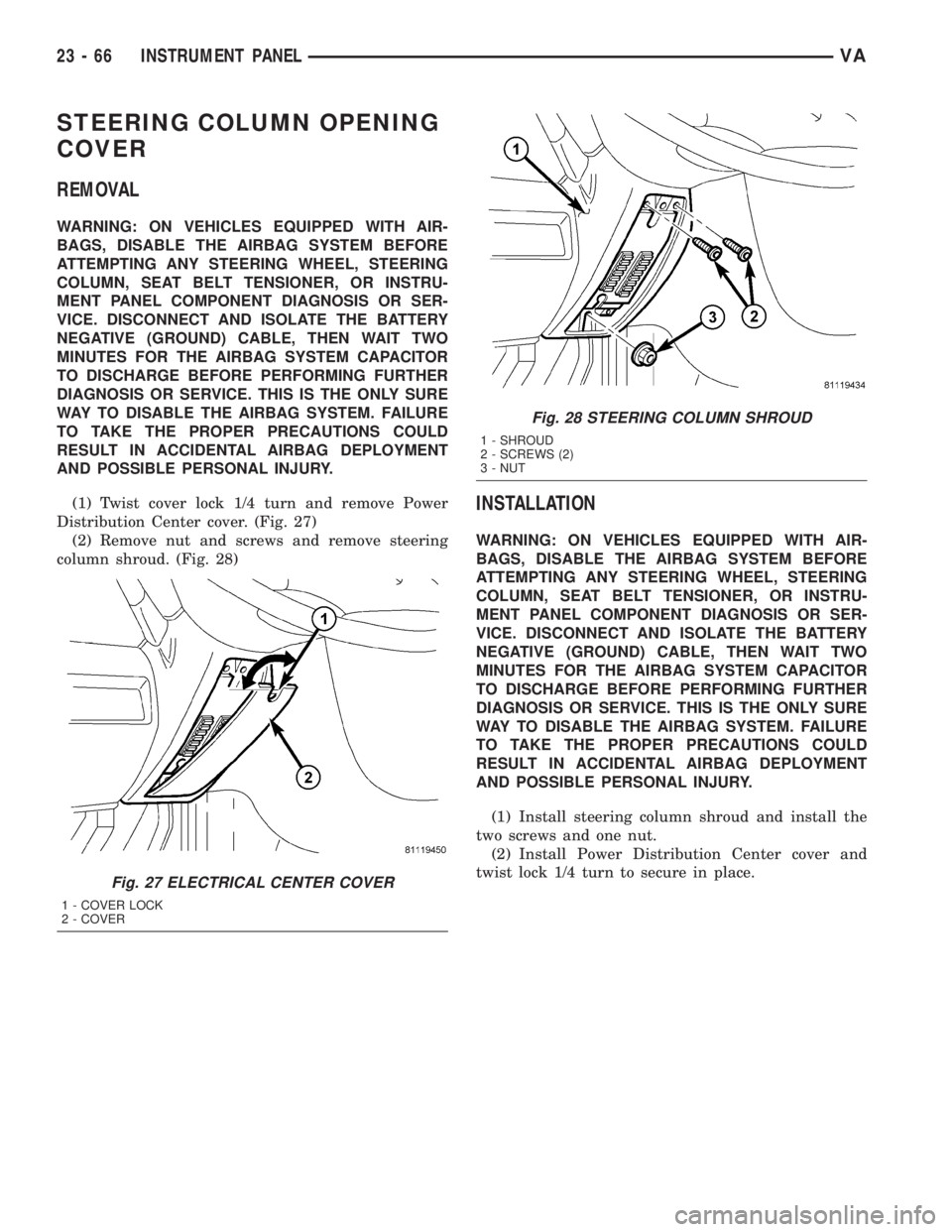
(1) Twist cover lock 1/4 turn and remove Power
Distribution Center cover. (Fig. 27)
(2) Remove nut and screws and remove steering
column shroud. (Fig. 28)
INSTALLATION
WARNING: ON VEHICLES EQUIPPED WITH AIR-
BAGS, DISABLE THE AIRBAG SYSTEM BEFORE
ATTEMPTING ANY STEERING WHEEL, STEERING
COLUMN, SEAT BELT TENSIONER, OR INSTRU-
MENT PANEL COMPONENT DIAGNOSIS OR SER-
VICE. DISCONNECT AND ISOLATE THE BATTERY
NEGATIVE (GROUND) CABLE, THEN WAIT TWO
MINUTES FOR THE AIRBAG SYSTEM CAPACITOR
TO DISCHARGE BEFORE PERFORMING FURTHER
DIAGNOSIS OR SERVICE. THIS IS THE ONLY SURE
WAY TO DISABLE THE AIRBAG SYSTEM. FAILURE
TO TAKE THE PROPER PRECAUTIONS COULD
RESULT IN ACCIDENTAL AIRBAG DEPLOYMENT
AND POSSIBLE PERSONAL INJURY.
(1) Install steering column shroud and install the
two screws and one nut.
(2) Install Power Distribution Center cover and
twist lock 1/4 turn to secure in place.
Fig. 27 ELECTRICAL CENTER COVER
1 - COVER LOCK
2 - COVER
Fig. 28 STEERING COLUMN SHROUD
1 - SHROUD
2 - SCREWS (2)
3 - NUT
23 - 66 INSTRUMENT PANELVA
Page 1112 of 1232
PAINT
TABLE OF CONTENTS
page page
PAINT
SPECIFICATIONS - PAINT CODES..........74
BASECOAT/CLEARCOAT FINISH
DESCRIPTION.........................74
PAINT TOUCH-UP
DESCRIPTION.........................74STANDARD PROCEDURE - PAINT TOUCH-UP . 75
FINESSE SANDING/BUFFING & POLISH
DESCRIPTION.........................75
PAINT
SPECIFICATIONS - PAINT CODES
EXTERIOR COLORS
EXTERIOR COLOR DAIMLERCHRYSLER
CODE
Steel Blue MB 5389
Brilliant Blue MB 5362
Orchid Green MB 6464
Flame Red MB 3534
Arctic White MB 9147
Black Blue MB 7103
Calcite Yellow MB 1234
Piedmont Red MB 3636
Hycanith Blue MB 5376
Black Gray MB 7103
Stone Gray MB 7160
Silver Gray MB 7708
BASECOAT/CLEARCOAT
FINISH
DESCRIPTION
The original equipment finish is a multi step pro-
cess that involves cleaning, applying electro de-posi-tion (E-coat), anti-chip primer, basecoat, and
clearcoat steps.
On most vehicles a two-part paint application
(basecoat/clearcoat) is used. Color paint that is
applied to primer is called basecoat. The clear coat
protects the basecoat from ultraviolet light and pro-
vides a durable high-gloss finish.
CAUTION: Do not use abrasive chemicals or com-
pounds on painted surfaces. Damage to finish can
result.
Do not use harsh alkaline based cleaning solvents
on painted surfaces. Damage to finish or color can
result.
PAINT TOUCH-UP
DESCRIPTION
When a painted metal surface has been scratched
or chipped, it should be touched-up as soon as possi-
ble to avoid corrosion. For best results, use MOPARt
Scratch Filler/Primer, Touch-Up Paints and Clear Top
Coat.
WARNING: USE AN OSHA APPROVED RESPIRATOR
AND SAFETY GLASSES WHEN SPRAYING PAINT
OR SOLVENTS IN A CONFINED AREA. PERSONAL
INJURY CAN RESULT.
23 - 74 PAINTVA
Page 1113 of 1232
STANDARD PROCEDURE - PAINT TOUCH-UP
(1) Scrape loose paint and corrosion from inside
scratch or chip.
(2) Clean affected area with MOPARtTar/Road
Oil Remover or equivalent, and allow to dry.
(3) Fill the inside of the scratch or chip with a coat
of filler/primer. Do not overlap primer onto good sur-
face finish. The applicator brush should be wet
enough to puddle-fill the scratch or chip without run-
ning. Do not stroke brush applicator on body surface.
Allow the filler/primer to dry hard.
(4) Cover the filler/primer with color touch-up
paint. Do not overlap touch-up color onto the original
color coat around the scratch or chip. Butt the new
color to the original color, if possible. Do not stroke
applicator brush on body surface. Allow touch-up
paint to dry hard.
(5) On vehicles without clearcoat, the touch-up
color can be lightly finesse sanded (1500 grit) and
polished with rubbing compound.
(6) On vehicles with clearcoat, apply clear top coat
to touch-up paint with the same technique as
described in Step 4. Allow clear top coat to dry hard.
If desired, Step 5 can be performed on clear top coat.
WARNING: AVOID PROLONGED SKIN CONTACT
WITH PETROLEUM OR ALCOHOL ± BASED CLEAN-ING SOLVENTS. PERSONAL INJURY CAN
RESULT.AVOID PROLONGED SKIN CONTACT WITH
PETROLEUM OR ALCOHOL ± BASED CLEANING
SOLVENTS. PERSONAL INJURY CAN RESULT.
FINESSE SANDING/BUFFING &
POLISH
DESCRIPTION
CAUTION: Do not remove more than .5 mils of
clearcoat finish, if equipped. Basecoat paint must
retain clearcoat for durability.
Use a Paint Thickness Gauge #PR-ETG-2X or equiv-
alent to determine film thickness before and after
the repair.
Minor acid etching, orange peel, or smudging in
clearcoat or single-stage finishes can be reduced with
light finesse sanding, hand buffing, and polishing.If
the finish has been finesse sanded in the past,
it cannot be repeated. Finesse sanding opera-
tion should be performed by a trained automo-
tive paint technician.
VAPAINT 23 - 75
PAINT TOUCH-UP (Continued)
Page 1119 of 1232
STATIONARY GLASS
TABLE OF CONTENTS
page page
BACKLITE - BULKHEAD TRIM PANEL
REMOVAL.............................81
INSTALLATION.........................81
QUARTER WINDOW
REMOVAL.............................81
INSTALLATION.........................81WINDSHIELD
WARNING
WINDSHIELD SAFETY PRECAUTIONS.....82
REMOVAL.............................82
INSTALLATION.........................83
BACKLITE - BULKHEAD TRIM
PANEL
REMOVAL
(1) Position an assistant opposite side of the bulk-
head trim panel to receive the glass and weatherstrip
seal.
(2) Start at an upper corner and separate the seal
from the window opening. Push the glass and seal
outward from the window opening. Remove the glass
and seal.
(3) Remove seal from glass if necessary.
(4) Clean the window opening.
INSTALLATION
(1) Install the weatherstrip seal on the window
glass. Verify that the glass is seated in the groove
around the edge of the seal.
(2) Insert an installation cord in the weatherstrip
seal inner groove.
NOTE: Use mineral spirits as a lubricant to aid seal
installation in the window opening.
(3) Position the glass and seal in the trim panel
opening.
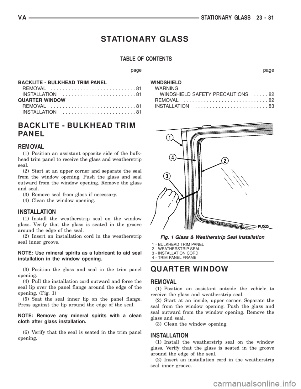
(4) Pull the installation cord outward and force the
seal lip over the panel flange around the edge of the
opening. (Fig. 1)
(5) Seat the seal inner lip on the panel flange.
Press against the lip around the edge of the seal.
NOTE: Remove any mineral spirits with a clean
cloth after glass installation.
(6) Verify that the seal is seated in the trim panel
opening.
QUARTER WINDOW
REMOVAL
(1) Position an assistant outside the vehicle to
receive the glass and weatherstrip seal.
(2) Start at an inside, upper corner. Separate the
seal from the window opening. Push the glass and
seal outward from the window opening. Remove the
glass and seal.
(3) Clean the window opening.
INSTALLATION
(1) Install the weatherstrip seal on the window
glass. Verify that the glass is seated in the groove
around the edge of the seal.
(2) Insert an installation cord in the weatherstrip
seal inner groove.
Fig. 1 Glass & Weatherstrip Seal Installation
1 - BULKHEAD TRIM PANEL
2 - WEATHERSTRIP SEAL
3 - INSTALLATION CORD
4 - TRIM PANEL FRAME
VASTATIONARY GLASS 23 - 81
Page 1120 of 1232
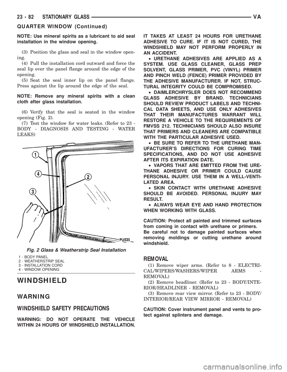
NOTE: Use mineral spirits as a lubricant to aid seal
installation in the window opening.
(3) Position the glass and seal in the window open-
ing.
(4) Pull the installation cord outward and force the
seal lip over the panel flange around the edge of the
opening.
(5) Seat the seal inner lip on the panel flange.
Press against the lip around the edge of the seal.
NOTE: Remove any mineral spirits with a clean
cloth after glass installation.
(6) Verify that the seal is seated in the window
opening (Fig. 2).
(7) Test the window for water leaks. (Refer to 23 -
BODY - DIAGNOSIS AND TESTING - WATER
LEAKS)
WINDSHIELD
WARNING
WINDSHIELD SAFETY PRECAUTIONS
WARNING: DO NOT OPERATE THE VEHICLE
WITHIN 24 HOURS OF WINDSHIELD INSTALLATION.IT TAKES AT LEAST 24 HOURS FOR URETHANE
ADHESIVE TO CURE. IF IT IS NOT CURED, THE
WINDSHIELD MAY NOT PERFORM PROPERLY IN
AN ACCIDENT.
²URETHANE ADHESIVES ARE APPLIED AS A
SYSTEM. USE GLASS CLEANER, GLASS PREP
SOLVENT, GLASS PRIMER, PVC (VINYL) PRIMER
AND PINCH WELD (FENCE) PRIMER PROVIDED BY
THE ADHESIVE MANUFACTURER. IF NOT, STRUC-
TURAL INTEGRITY COULD BE COMPROMISED.
²DAIMLERCHRYSLER DOES NOT RECOMMEND
GLASS ADHESIVE BY BRAND. TECHNICIANS
SHOULD REVIEW PRODUCT LABELS AND TECHNI-
CAL DATA SHEETS, AND USE ONLY ADHESIVES
THAT THEIR MANUFACTURES WARRANT WILL
RESTORE A VEHICLE TO THE REQUIREMENTS OF
FMVSS 212. TECHNICIANS SHOULD ALSO INSURE
THAT PRIMERS AND CLEANERS ARE COMPATIBLE
WITH THE PARTICULAR ADHESIVE USED.
²BE SURE TO REFER TO THE URETHANE MAN-
UFACTURER'S DIRECTIONS FOR CURING TIME
SPECIFICATIONS, AND DO NOT USE ADHESIVE
AFTER ITS EXPIRATION DATE.
²VAPORS THAT ARE EMITTED FROM THE URE-
THANE ADHESIVE OR PRIMER COULD CAUSE
PERSONAL INJURY. USE THEM IN A WELL-VENTI-
LATED AREA.
²SKIN CONTACT WITH URETHANE ADHESIVE
SHOULD BE AVOIDED. PERSONAL INJURY MAY
RESULT.
²ALWAYS WEAR EYE AND HAND PROTECTION
WHEN WORKING WITH GLASS.
CAUTION: Protect all painted and trimmed surfaces
from coming in contact with urethane or primers.
Be careful not to damage painted surfaces when
removing moldings or cutting urethane around
windshield.
REMOVAL
(1) Remove wiper arms. (Refer to 8 - ELECTRI-
CAL/WIPERS/WASHERS/WIPER ARMS -
REMOVAL)
(2) Remove headliner. (Refer to 23 - BODY/INTE-
RIOR/HEADLINER - REMOVAL)
(3) Remove rear view mirror. (Refer to 23 - BODY/
INTERIOR/REAR VIEW MIRROR - REMOVAL)
CAUTION: Cover instrument panel and vents to pro-
tect against splinters and damage.
Fig. 2 Glass & Weatherstrip Seal Installation
1 - BODY PANEL
2 - WEATHERSTRIP SEAL
3 - INSTALLATION CORD
4 - WINDOW OPENING
23 - 82 STATIONARY GLASSVA
QUARTER WINDOW (Continued)
Page 1121 of 1232
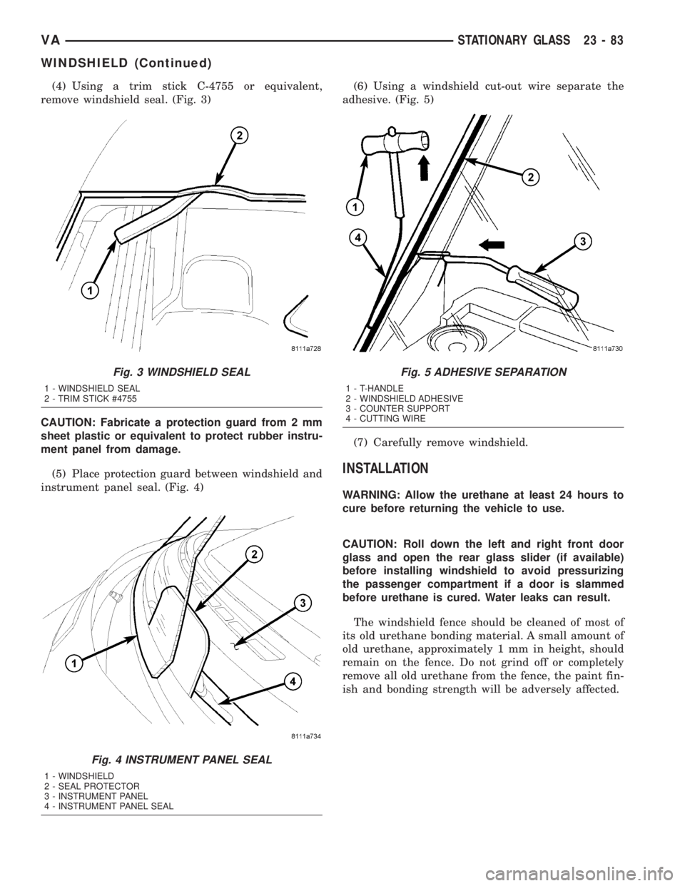
(4) Using a trim stick C-4755 or equivalent,
remove windshield seal. (Fig. 3)
CAUTION: Fabricate a protection guard from 2 mm
sheet plastic or equivalent to protect rubber instru-
ment panel from damage.
(5) Place protection guard between windshield and
instrument panel seal. (Fig. 4)(6) Using a windshield cut-out wire separate the
adhesive. (Fig. 5)
(7) Carefully remove windshield.
INSTALLATION
WARNING: Allow the urethane at least 24 hours to
cure before returning the vehicle to use.
CAUTION: Roll down the left and right front door
glass and open the rear glass slider (if available)
before installing windshield to avoid pressurizing
the passenger compartment if a door is slammed
before urethane is cured. Water leaks can result.
The windshield fence should be cleaned of most of
its old urethane bonding material. A small amount of
old urethane, approximately 1 mm in height, should
remain on the fence. Do not grind off or completely
remove all old urethane from the fence, the paint fin-
ish and bonding strength will be adversely affected.
Fig. 3 WINDSHIELD SEAL
1 - WINDSHIELD SEAL
2 - TRIM STICK #4755
Fig. 4 INSTRUMENT PANEL SEAL
1 - WINDSHIELD
2 - SEAL PROTECTOR
3 - INSTRUMENT PANEL
4 - INSTRUMENT PANEL SEAL
Fig. 5 ADHESIVE SEPARATION
1 - T-HANDLE
2 - WINDSHIELD ADHESIVE
3 - COUNTER SUPPORT
4 - CUTTING WIRE
VASTATIONARY GLASS 23 - 83
WINDSHIELD (Continued)
Page 1131 of 1232
To maintain minimum evaporator temperature and
prevent evaporator freezing, an evaporator tempera-
ture sensor is used.
Vehicles equipped with the available rear A/C sys-
tem have an individual temperature control and
blower motor speed switches. When the rear A/C sys-
tem is turned on, a solenoid valve opens the rear
refrigerant circuit and activates the blower motor for
the rear evaporator. The circulated internal air tem-
perature is measured by a temperature sensor and
the temperature value is compared within the rear
A/C control module to an adjusted value at the tem-
perature control switch. To prevent icing of the rear
evaporator, the temperature switch cuts off the flow
of refrigerant through the rear A/C circuit by de-en-
ergizing the solenoid valve.
The front and rear A/C systems are designed for
the use of non-CFC, R-134a refrigerant only. Both
the front and rear systems use an expansion valve to
meter refrigerant flow to the evaporator.
DIAGNOSIS AND TESTING
DIAGNOSIS AND TESTING - FUNCTION TEST
The ATC system can perform an self-test, which
can be activated by the DRBIIItscan tool to confirm
that the air conditioning system is performing satis-
factorily. This test provides a quick confirmation of
heater - air conditioning system performance to the
service technician. Refer to Body Diagnostic Proce-
dures for the appropriate diagnostic information.
DIAGNOSIS AND TESTING - A/C
PERFORMANCE TEST
The air conditioning system is designed to provide
the passenger compartment with low temperature
and low specific humidity air. The evaporator, located
in the heater housing on the dash panel below the
instrument panel, is cooled to temperatures near the
freezing point. As warm damp air passes through the
cooled evaporator, the air transfers its heat to the
refrigerant in the evaporator and the moisture in the
air condenses on the evaporator fins. During periods
of high heat and humidity, an air conditioning sys-
tem will be more effective in the Recirculation Mode.
With the system in the Recirculation Mode, only air
from the passenger compartment passes through the
evaporator. As the passenger compartment air dehu-
midifies, the air conditioning system performance
levels improve.
Humidity has an important bearing on the temper-
ature of the air delivered to the interior of the vehi-
cle. It is important to understand the effect that
humidity has on the performance of the air condition-
ing system. When humidity is high, the evaporatorhas to perform a double duty. It must lower the air
temperature, and it must lower the temperature of
the moisture in the air that condenses on the evapo-
rator fins. Condensing the moisture in the air trans-
fers heat energy into the evaporator fins and tubing.
This reduces the amount of heat the evaporator can
absorb from the air. High humidity greatly reduces
the ability of the evaporator to lower the temperature
of the air.
However, evaporator capacity used to reduce the
amount of moisture in the air is not wasted. Remov-
ing some of the moisture out of the air entering the
vehicle adds to the comfort of the passengers.
Although, an owner may expect too much from their
air conditioning system on humid days. A perfor-
mance test is the best way to determine whether the
system is performing up to standard. This test also
provides valuable clues as to the possible cause of
trouble with the air conditioning system.
WARNING: REFER TO THE APPLICABLE WARN-
INGS AND CAUTIONS FOR THIS SYSTEM BEFORE
PERFORMING THE FOLLOWING OPERATION (Refer
to 24 - HEATING & AIR CONDITIONING/PLUMBING -
WARNING) and (Refer to 24 - HEATING & AIR CON-
DITIONING/PLUMBING - CAUTION).
NOTE: Very specific instructions and conditions
pertain to this procedure which are significantly dif-
ferent than procedures used in other vehicle appli-
cations. Follow each step in the order they are
presented. Do not skip steps or change conditions
from those stated or results will be adversely
affected and invalid.
The compressor clutch is de-energized under any of
the following conditions:
²Blocked compressor (thermal fuse in the pulley)
²Low pressure in the system
²Low evaporator temperature
²Hard acceleration (WOT)
²High coolant temperatures
(1) Place the vehicle in the shade with all widows
open.
(2) Turn the temperature control to cold.
(3) Select Fresh Air, not Recirculate and open all
air conditioning duct louvers.
(4) Start the vehicle and allow it to idle.
(5) Turn the blower switch to the maximum blower
speed setting and allow to operate for a short period
of time before proceeding.
(6) Perform an outlet temperature test as follows:
a. Turn the blower switch to the lowest blower
speed setting.
b. Insert a thermometer into a center duct for at
least five minutes.
VAHEATING & AIR CONDITIONING 24 - 3
HEATING & AIR CONDITIONING (Continued)
Page 1140 of 1232
(11) Reconnect the engine wire harness connector
for the compressor clutch coil to the coil wire harness
connector on the top of the compressor.
(12) Reinstall the serpentine accessory drive belt
(Refer to 7 - COOLING/ACCESSORY DRIVE/DRIVE
BELTS - INSTALLATION).
(13) Reconnect the battery negative cable.
(14) If a new clutch plate and/or clutch pulley are
being installed, the new clutch components must be
burnished (Refer to 24 - HEATING & AIR CONDI-
TIONING/CONTROLS/A/C COMPRESSOR CLUTCH
- STANDARD PROCEDURE).
A/C COMPRESSOR CLUTCH
COIL
DIAGNOSIS AND TESTING - COMPRESSOR
CLUTCH COIL
The air conditioning compressor clutch coil electri-
cal circuit is controlled by the ATC control module
which is integral to the heater-A/C control. Begin
testing of a suspected compressor clutch coil problem
by performing the ATC Function Test using the
DRBIIItscan tool.
A/C HEATER CONTROL
DESCRIPTION
This ATC system uses a combination of electrical
and mechanical controls. These controls provide the
vehicle operator with a number of setting options to
help control the climate and comfort within the vehi-
cle.
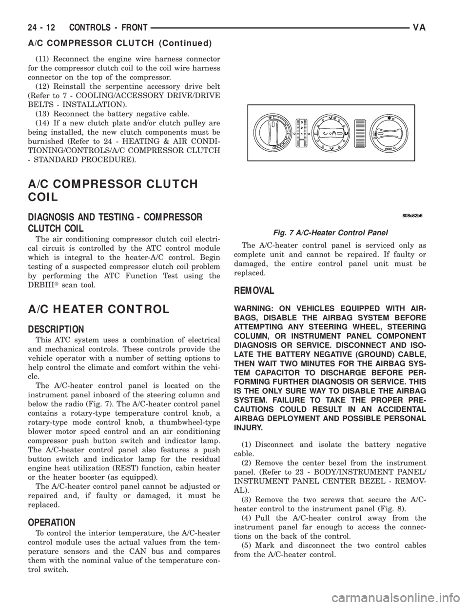
The A/C-heater control panel is located on the
instrument panel inboard of the steering column and
below the radio (Fig. 7). The A/C-heater control panel
contains a rotary-type temperature control knob, a
rotary-type mode control knob, a thumbwheel-type
blower motor speed control and an air conditioning
compressor push button switch and indicator lamp.
The A/C-heater control panel also features a push
button switch and indicator lamp for the residual
engine heat utilization (REST) function, cabin heater
or the heater booster (as equipped).
The A/C-heater control panel cannot be adjusted or
repaired and, if faulty or damaged, it must be
replaced.
OPERATION
To control the interior temperature, the A/C-heater
control module uses the actual values from the tem-
perature sensors and the CAN bus and compares
them with the nominal value of the temperature con-
trol switch.The A/C-heater control panel is serviced only as
complete unit and cannot be repaired. If faulty or
damaged, the entire control panel unit must be
replaced.
REMOVAL
WARNING: ON VEHICLES EQUIPPED WITH AIR-
BAGS, DISABLE THE AIRBAG SYSTEM BEFORE
ATTEMPTING ANY STEERING WHEEL, STEERING
COLUMN, OR INSTRUMENT PANEL COMPONENT
DIAGNOSIS OR SERVICE. DISCONNECT AND ISO-
LATE THE BATTERY NEGATIVE (GROUND) CABLE,
THEN WAIT TWO MINUTES FOR THE AIRBAG SYS-
TEM CAPACITOR TO DISCHARGE BEFORE PER-
FORMING FURTHER DIAGNOSIS OR SERVICE. THIS
IS THE ONLY SURE WAY TO DISABLE THE AIRBAG
SYSTEM. FAILURE TO TAKE THE PROPER PRE-
CAUTIONS COULD RESULT IN AN ACCIDENTAL
AIRBAG DEPLOYMENT AND POSSIBLE PERSONAL
INJURY.
(1) Disconnect and isolate the battery negative
cable.
(2) Remove the center bezel from the instrument
panel. (Refer to 23 - BODY/INSTRUMENT PANEL/
INSTRUMENT PANEL CENTER BEZEL - REMOV-
AL).
(3) Remove the two screws that secure the A/C-
heater control to the instrument panel (Fig. 8).
(4) Pull the A/C-heater control away from the
instrument panel far enough to access the connec-
tions on the back of the control.
(5) Mark and disconnect the two control cables
from the A/C-heater control.
Fig. 7 A/C-Heater Control Panel
24 - 12 CONTROLS - FRONTVA
A/C COMPRESSOR CLUTCH (Continued)