2005 MERCEDES-BENZ SPRINTER engine
[x] Cancel search: enginePage 701 of 1232
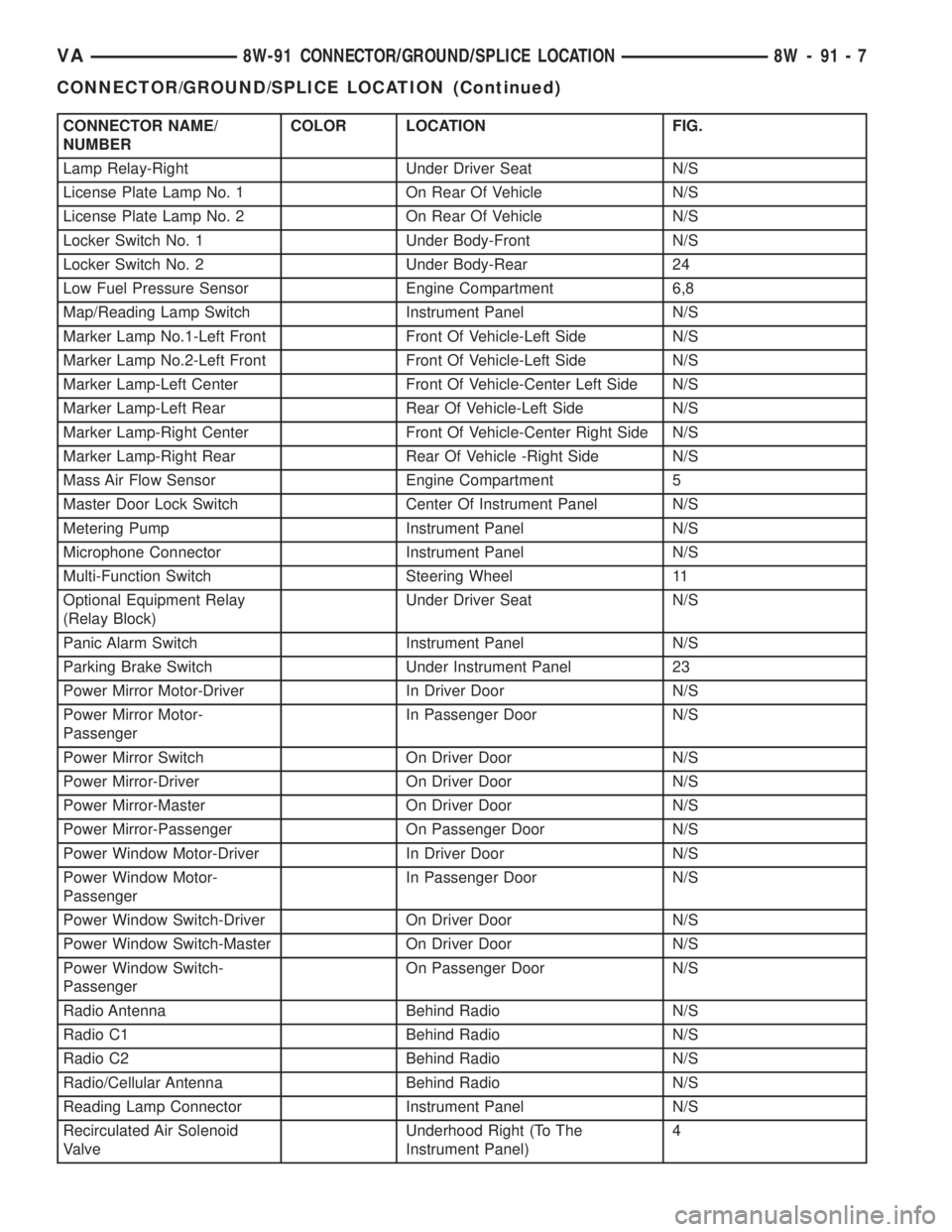
CONNECTOR NAME/
NUMBERCOLOR LOCATION FIG.
Lamp Relay-Right Under Driver Seat N/S
License Plate Lamp No. 1 On Rear Of Vehicle N/S
License Plate Lamp No. 2 On Rear Of Vehicle N/S
Locker Switch No. 1 Under Body-Front N/S
Locker Switch No. 2 Under Body-Rear 24
Low Fuel Pressure Sensor Engine Compartment 6,8
Map/Reading Lamp Switch Instrument Panel N/S
Marker Lamp No.1-Left Front Front Of Vehicle-Left Side N/S
Marker Lamp No.2-Left Front Front Of Vehicle-Left Side N/S
Marker Lamp-Left Center Front Of Vehicle-Center Left Side N/S
Marker Lamp-Left Rear Rear Of Vehicle-Left Side N/S
Marker Lamp-Right Center Front Of Vehicle-Center Right Side N/S
Marker Lamp-Right Rear Rear Of Vehicle -Right Side N/S
Mass Air Flow Sensor Engine Compartment 5
Master Door Lock Switch Center Of Instrument Panel N/S
Metering Pump Instrument Panel N/S
Microphone Connector Instrument Panel N/S
Multi-Function Switch Steering Wheel 11
Optional Equipment Relay
(Relay Block)Under Driver Seat N/S
Panic Alarm Switch Instrument Panel N/S
Parking Brake Switch Under Instrument Panel 23
Power Mirror Motor-Driver In Driver Door N/S
Power Mirror Motor-
PassengerIn Passenger Door N/S
Power Mirror Switch On Driver Door N/S
Power Mirror-Driver On Driver Door N/S
Power Mirror-Master On Driver Door N/S
Power Mirror-Passenger On Passenger Door N/S
Power Window Motor-Driver In Driver Door N/S
Power Window Motor-
PassengerIn Passenger Door N/S
Power Window Switch-Driver On Driver Door N/S
Power Window Switch-Master On Driver Door N/S
Power Window Switch-
PassengerOn Passenger Door N/S
Radio Antenna Behind Radio N/S
Radio C1 Behind Radio N/S
Radio C2 Behind Radio N/S
Radio/Cellular Antenna Behind Radio N/S
Reading Lamp Connector Instrument Panel N/S
Recirculated Air Solenoid
ValveUnderhood Right (To The
Instrument Panel)4
VA8W-91 CONNECTOR/GROUND/SPLICE LOCATION 8W - 91 - 7
CONNECTOR/GROUND/SPLICE LOCATION (Continued)
Page 702 of 1232
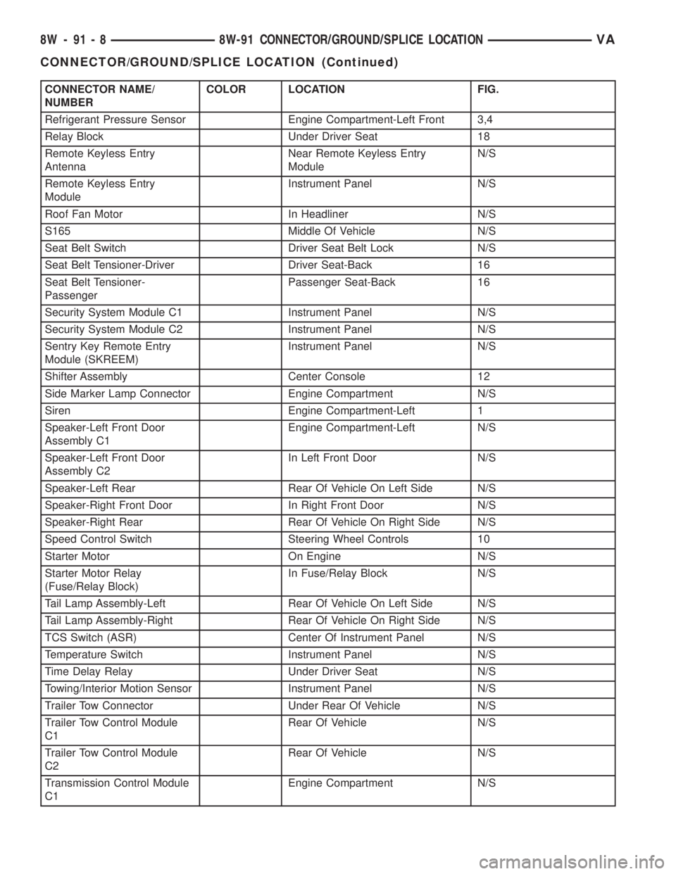
CONNECTOR NAME/
NUMBERCOLOR LOCATION FIG.
Refrigerant Pressure Sensor Engine Compartment-Left Front 3,4
Relay Block Under Driver Seat 18
Remote Keyless Entry
AntennaNear Remote Keyless Entry
ModuleN/S
Remote Keyless Entry
ModuleInstrument Panel N/S
Roof Fan Motor In Headliner N/S
S165 Middle Of Vehicle N/S
Seat Belt Switch Driver Seat Belt Lock N/S
Seat Belt Tensioner-Driver Driver Seat-Back 16
Seat Belt Tensioner-
PassengerPassenger Seat-Back 16
Security System Module C1 Instrument Panel N/S
Security System Module C2 Instrument Panel N/S
Sentry Key Remote Entry
Module (SKREEM)Instrument Panel N/S
Shifter Assembly Center Console 12
Side Marker Lamp Connector Engine Compartment N/S
Siren Engine Compartment-Left 1
Speaker-Left Front Door
Assembly C1Engine Compartment-Left N/S
Speaker-Left Front Door
Assembly C2In Left Front Door N/S
Speaker-Left Rear Rear Of Vehicle On Left Side N/S
Speaker-Right Front Door In Right Front Door N/S
Speaker-Right Rear Rear Of Vehicle On Right Side N/S
Speed Control Switch Steering Wheel Controls 10
Starter Motor On Engine N/S
Starter Motor Relay
(Fuse/Relay Block)In Fuse/Relay Block N/S
Tail Lamp Assembly-Left Rear Of Vehicle On Left Side N/S
Tail Lamp Assembly-Right Rear Of Vehicle On Right Side N/S
TCS Switch (ASR) Center Of Instrument Panel N/S
Temperature Switch Instrument Panel N/S
Time Delay Relay Under Driver Seat N/S
Towing/Interior Motion Sensor Instrument Panel N/S
Trailer Tow Connector Under Rear Of Vehicle N/S
Trailer Tow Control Module
C1Rear Of Vehicle N/S
Trailer Tow Control Module
C2Rear Of Vehicle N/S
Transmission Control Module
C1Engine Compartment N/S
8W - 91 - 8 8W-91 CONNECTOR/GROUND/SPLICE LOCATIONVA
CONNECTOR/GROUND/SPLICE LOCATION (Continued)
Page 703 of 1232
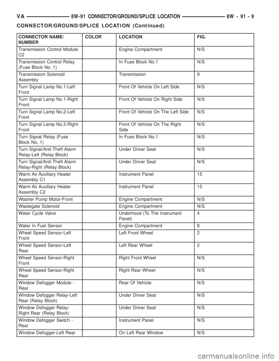
CONNECTOR NAME/
NUMBERCOLOR LOCATION FIG.
Transmission Control Module
C2Engine Compartment N/S
Transmission Control Relay
(Fuse Block No. 1)In Fuse Block No.1 N/S
Transmission Solenoid
AssemblyTransmission 9
Turn Signal Lamp No.1-Left
FrontFront Of Vehicle On Left Side N/S
Turn Signal Lamp No.1-Right
FrontFront Of Vehicle On Right Side N/S
Turn Signal Lamp No.2-Left
FrontFront Of Vehicle On The Left Side N/S
Turn Signal Lamp No.2-Right
FrontFront Of Vehicle On The Right
SideN/S
Turn Signal Relay (Fuse
Block No. 1)In Fuse Block No.1 N/S
Turn Signal/Anti-Theft Alarm
Relay-Left (Relay Block)Under Driver Seat N/S
Turn Signal/Anti-Theft Alarm
Relay-Right (Relay Block)Under Driver Seat N/S
Warm Air Auxiliary Heater
Assembly C1Instrument Panel 15
Warm Air Auxiliary Heater
Assembly C2Instrument Panel 15
Washer Pump Motor-Front Engine Compartment N/S
Wastegate Solenoid Engine Compartment N/S
Water Cycle Valve Underhood (To The Instrument
Panel)4
Water In Fuel Sensor Engine Compartment 8
Wheel Speed Sensor-Left
FrontLeft Front Wheel 2
Wheel Speed Sensor-Left
RearLeft Rear Wheel 2
Wheel Speed Sensor-Right
FrontRight Front Wheel N/S
Wheel Speed Sensor-Right
RearRight Rear Wheel N/S
Window Defogger Module -
RearRear Of Vehicle N/S
Window Defogger Relay-Left
Rear (Relay Block)Under Driver Seat N/S
Window Defogger Relay-
Right Rear (Relay Block)Under Driver Seat N/S
Window Defogger Switch -
RearInstrument Panel N/S
Window Defogger-Left Rear On Left Rear Window N/S
VA8W-91 CONNECTOR/GROUND/SPLICE LOCATION 8W - 91 - 9
CONNECTOR/GROUND/SPLICE LOCATION (Continued)
Page 704 of 1232
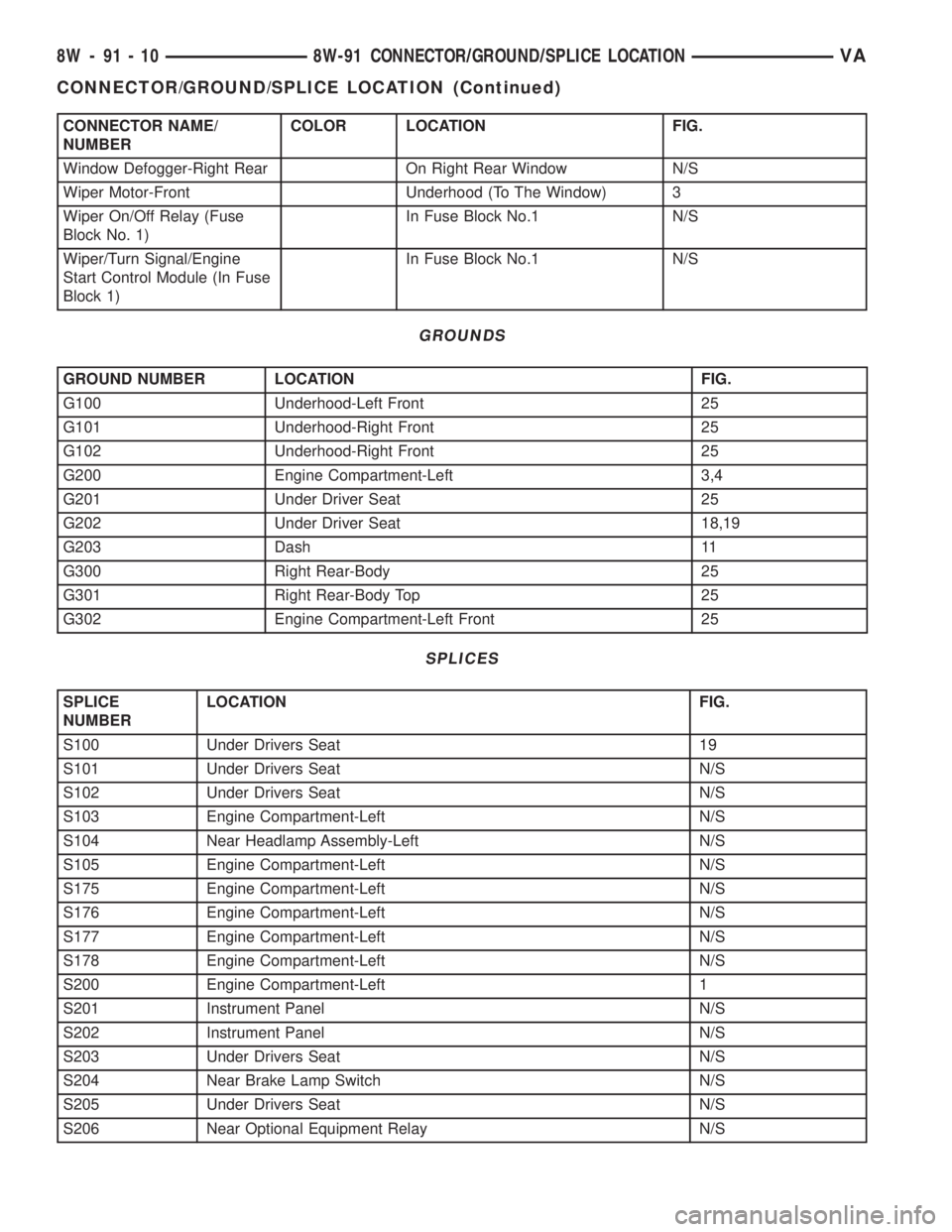
CONNECTOR NAME/
NUMBERCOLOR LOCATION FIG.
Window Defogger-Right Rear On Right Rear Window N/S
Wiper Motor-Front Underhood (To The Window) 3
Wiper On/Off Relay (Fuse
Block No. 1)In Fuse Block No.1 N/S
Wiper/Turn Signal/Engine
Start Control Module (In Fuse
Block 1)In Fuse Block No.1 N/S
GROUNDS
GROUND NUMBER LOCATION FIG.
G100 Underhood-Left Front 25
G101 Underhood-Right Front 25
G102 Underhood-Right Front 25
G200 Engine Compartment-Left 3,4
G201 Under Driver Seat 25
G202 Under Driver Seat 18,19
G203 Dash 11
G300 Right Rear-Body 25
G301 Right Rear-Body Top 25
G302 Engine Compartment-Left Front 25
SPLICES
SPLICE
NUMBERLOCATION FIG.
S100 Under Drivers Seat 19
S101 Under Drivers Seat N/S
S102 Under Drivers Seat N/S
S103 Engine Compartment-Left N/S
S104 Near Headlamp Assembly-Left N/S
S105 Engine Compartment-Left N/S
S175 Engine Compartment-Left N/S
S176 Engine Compartment-Left N/S
S177 Engine Compartment-Left N/S
S178 Engine Compartment-Left N/S
S200 Engine Compartment-Left 1
S201 Instrument Panel N/S
S202 Instrument Panel N/S
S203 Under Drivers Seat N/S
S204 Near Brake Lamp Switch N/S
S205 Under Drivers Seat N/S
S206 Near Optional Equipment Relay N/S
8W - 91 - 10 8W-91 CONNECTOR/GROUND/SPLICE LOCATIONVA
CONNECTOR/GROUND/SPLICE LOCATION (Continued)
Page 705 of 1232
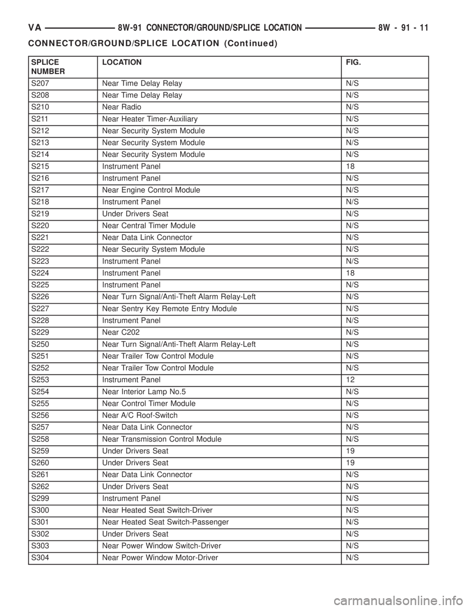
SPLICE
NUMBERLOCATION FIG.
S207 Near Time Delay Relay N/S
S208 Near Time Delay Relay N/S
S210 Near Radio N/S
S211 Near Heater Timer-Auxiliary N/S
S212 Near Security System Module N/S
S213 Near Security System Module N/S
S214 Near Security System Module N/S
S215 Instrument Panel 18
S216 Instrument Panel N/S
S217 Near Engine Control Module N/S
S218 Instrument Panel N/S
S219 Under Drivers Seat N/S
S220 Near Central Timer Module N/S
S221 Near Data Link Connector N/S
S222 Near Security System Module N/S
S223 Instrument Panel N/S
S224 Instrument Panel 18
S225 Instrument Panel N/S
S226 Near Turn Signal/Anti-Theft Alarm Relay-Left N/S
S227 Near Sentry Key Remote Entry Module N/S
S228 Instrument Panel N/S
S229 Near C202 N/S
S250 Near Turn Signal/Anti-Theft Alarm Relay-Left N/S
S251 Near Trailer Tow Control Module N/S
S252 Near Trailer Tow Control Module N/S
S253 Instrument Panel 12
S254 Near Interior Lamp No.5 N/S
S255 Near Control Timer Module N/S
S256 Near A/C Roof-Switch N/S
S257 Near Data Link Connector N/S
S258 Near Transmission Control Module N/S
S259 Under Drivers Seat 19
S260 Under Drivers Seat 19
S261 Near Data Link Connector N/S
S262 Under Drivers Seat N/S
S299 Instrument Panel N/S
S300 Near Heated Seat Switch-Driver N/S
S301 Near Heated Seat Switch-Passenger N/S
S302 Under Drivers Seat N/S
S303 Near Power Window Switch-Driver N/S
S304 Near Power Window Motor-Driver N/S
VA8W-91 CONNECTOR/GROUND/SPLICE LOCATION 8W - 91 - 11
CONNECTOR/GROUND/SPLICE LOCATION (Continued)
Page 706 of 1232
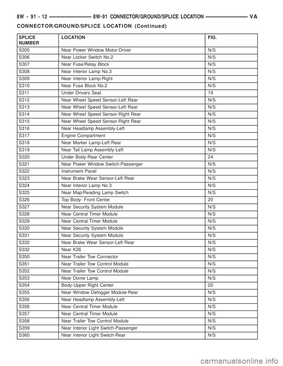
SPLICE
NUMBERLOCATION FIG.
S305 Near Power Window Motor-Driver N/S
S306 Near Locker Switch No.2 N/S
S307 Near Fuse/Relay Block N/S
S308 Near Interior Lamp No.3 N/S
S309 Near Interior Lamp-Right N/S
S310 Near Fuse Block No.2 N/S
S311 Under Drivers Seat 19
S312 Near Wheel Speed Sensor-Left Rear N/S
S313 Near Wheel Speed Sensor-Left Rear N/S
S314 Near Wheel Speed Sensor-Right Rear N/S
S315 Near Wheel Speed Sensor-Right Rear N/S
S316 Near Headlamp Assembly-Left N/S
S317 Engine Compartment N/S
S318 Near Marker Lamp-Left Rear N/S
S319 Near Tail Lamp Assembly-Left N/S
S320 Under Body-Rear Center 24
S321 Near Power Window Switch-Passenger N/S
S322 Instrument Panel N/S
S323 Near Brake Wear Sensor-Left Rear N/S
S324 Near Interior Lamp No.3 N/S
S325 Near Map/Reading Lamp Switch N/S
S326 Top Body- Front Center 20
S327 Near Security System Module N/S
S328 Near Central Timer Module N/S
S329 Near Central Timer Module N/S
S330 Near Security System Module N/S
S331 Near Security System Module N/S
S332 Near Brake Wear Sensor-Left Rear N/S
S332 Near K26 N/S
S350 Near Trailer Tow Connector N/S
S351 Near Trailer Tow Control Module N/S
S352 Near Trailer Tow Control Module N/S
S353 Near Dome Lamp N/S
S354 Body-Upper Right Center 20
S355 Near Window Defogger Module-Rear N/S
S356 Near Headlamp Assembly-Left N/S
S356 Near Central Timer Module N/S
S357 Near Central Timer Module N/S
S358 Near Trailer Tow Control Module N/S
S359 Near Interior Light Switch-Passenger N/S
S360 Near Interior Light Switch-Rear N/S
8W - 91 - 12 8W-91 CONNECTOR/GROUND/SPLICE LOCATIONVA
CONNECTOR/GROUND/SPLICE LOCATION (Continued)
Page 735 of 1232
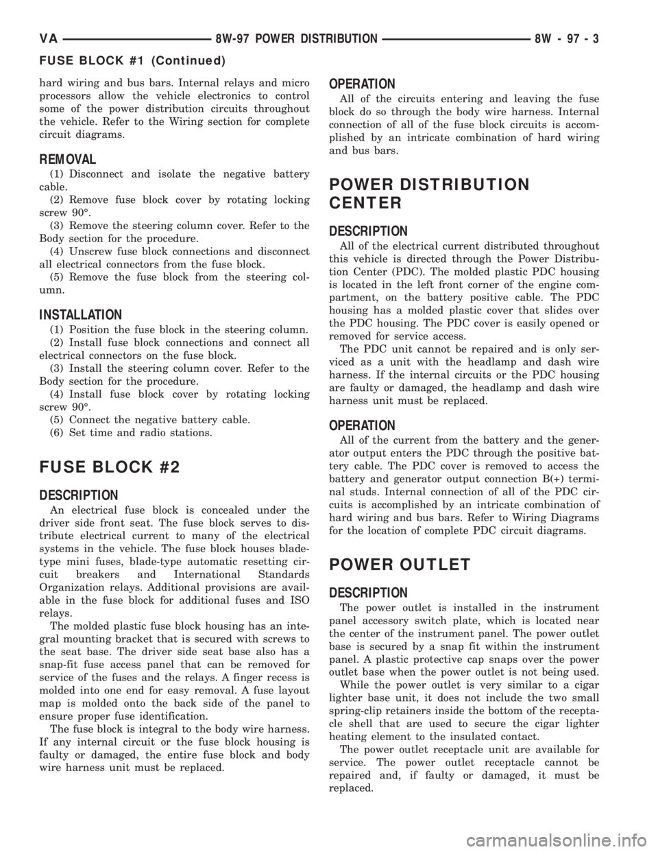
hard wiring and bus bars. Internal relays and micro
processors allow the vehicle electronics to control
some of the power distribution circuits throughout
the vehicle. Refer to the Wiring section for complete
circuit diagrams.
REMOVAL
(1) Disconnect and isolate the negative battery
cable.
(2) Remove fuse block cover by rotating locking
screw 90É.
(3) Remove the steering column cover. Refer to the
Body section for the procedure.
(4) Unscrew fuse block connections and disconnect
all electrical connectors from the fuse block.
(5) Remove the fuse block from the steering col-
umn.
INSTALLATION
(1) Position the fuse block in the steering column.
(2) Install fuse block connections and connect all
electrical connectors on the fuse block.
(3) Install the steering column cover. Refer to the
Body section for the procedure.
(4) Install fuse block cover by rotating locking
screw 90É.
(5) Connect the negative battery cable.
(6) Set time and radio stations.
FUSE BLOCK #2
DESCRIPTION
An electrical fuse block is concealed under the
driver side front seat. The fuse block serves to dis-
tribute electrical current to many of the electrical
systems in the vehicle. The fuse block houses blade-
type mini fuses, blade-type automatic resetting cir-
cuit breakers and International Standards
Organization relays. Additional provisions are avail-
able in the fuse block for additional fuses and ISO
relays.
The molded plastic fuse block housing has an inte-
gral mounting bracket that is secured with screws to
the seat base. The driver side seat base also has a
snap-fit fuse access panel that can be removed for
service of the fuses and the relays. A finger recess is
molded into one end for easy removal. A fuse layout
map is molded onto the back side of the panel to
ensure proper fuse identification.
The fuse block is integral to the body wire harness.
If any internal circuit or the fuse block housing is
faulty or damaged, the entire fuse block and body
wire harness unit must be replaced.
OPERATION
All of the circuits entering and leaving the fuse
block do so through the body wire harness. Internal
connection of all of the fuse block circuits is accom-
plished by an intricate combination of hard wiring
and bus bars.
POWER DISTRIBUTION
CENTER
DESCRIPTION
All of the electrical current distributed throughout
this vehicle is directed through the Power Distribu-
tion Center (PDC). The molded plastic PDC housing
is located in the left front corner of the engine com-
partment, on the battery positive cable. The PDC
housing has a molded plastic cover that slides over
the PDC housing. The PDC cover is easily opened or
removed for service access.
The PDC unit cannot be repaired and is only ser-
viced as a unit with the headlamp and dash wire
harness. If the internal circuits or the PDC housing
are faulty or damaged, the headlamp and dash wire
harness unit must be replaced.
OPERATION
All of the current from the battery and the gener-
ator output enters the PDC through the positive bat-
tery cable. The PDC cover is removed to access the
battery and generator output connection B(+) termi-
nal studs. Internal connection of all of the PDC cir-
cuits is accomplished by an intricate combination of
hard wiring and bus bars. Refer to Wiring Diagrams
for the location of complete PDC circuit diagrams.
POWER OUTLET
DESCRIPTION
The power outlet is installed in the instrument
panel accessory switch plate, which is located near
the center of the instrument panel. The power outlet
base is secured by a snap fit within the instrument
panel. A plastic protective cap snaps over the power
outlet base when the power outlet is not being used.
While the power outlet is very similar to a cigar
lighter base unit, it does not include the two small
spring-clip retainers inside the bottom of the recepta-
cle shell that are used to secure the cigar lighter
heating element to the insulated contact.
The power outlet receptacle unit are available for
service. The power outlet receptacle cannot be
repaired and, if faulty or damaged, it must be
replaced.
VA8W-97 POWER DISTRIBUTION 8W - 97 - 3
FUSE BLOCK #1 (Continued)
Page 739 of 1232
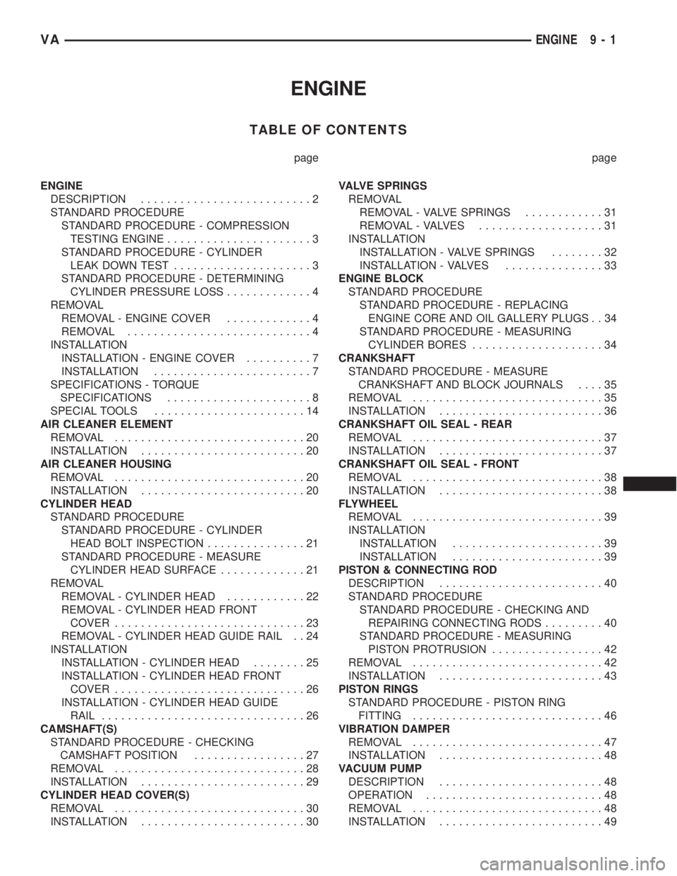
ENGINE
TABLE OF CONTENTS
page page
ENGINE
DESCRIPTION..........................2
STANDARD PROCEDURE
STANDARD PROCEDURE - COMPRESSION
TESTING ENGINE......................3
STANDARD PROCEDURE - CYLINDER
LEAK DOWN TEST.....................3
STANDARD PROCEDURE - DETERMINING
CYLINDER PRESSURE LOSS.............4
REMOVAL
REMOVAL - ENGINE COVER.............4
REMOVAL............................4
INSTALLATION
INSTALLATION - ENGINE COVER..........7
INSTALLATION........................7
SPECIFICATIONS - TORQUE
SPECIFICATIONS......................8
SPECIAL TOOLS.......................14
AIR CLEANER ELEMENT
REMOVAL.............................20
INSTALLATION.........................20
AIR CLEANER HOUSING
REMOVAL.............................20
INSTALLATION.........................20
CYLINDER HEAD
STANDARD PROCEDURE
STANDARD PROCEDURE - CYLINDER
HEAD BOLT INSPECTION...............21
STANDARD PROCEDURE - MEASURE
CYLINDER HEAD SURFACE.............21
REMOVAL
REMOVAL - CYLINDER HEAD............22
REMOVAL - CYLINDER HEAD FRONT
COVER.............................23
REMOVAL - CYLINDER HEAD GUIDE RAIL . . 24
INSTALLATION
INSTALLATION - CYLINDER HEAD........25
INSTALLATION - CYLINDER HEAD FRONT
COVER.............................26
INSTALLATION - CYLINDER HEAD GUIDE
RAIL...............................26
CAMSHAFT(S)
STANDARD PROCEDURE - CHECKING
CAMSHAFT POSITION.................27
REMOVAL.............................28
INSTALLATION.........................29
CYLINDER HEAD COVER(S)
REMOVAL.............................30
INSTALLATION.........................30VALVE SPRINGS
REMOVAL
REMOVAL - VALVE SPRINGS............31
REMOVAL - VALVES...................31
INSTALLATION
INSTALLATION - VALVE SPRINGS........32
INSTALLATION - VALVES...............33
ENGINE BLOCK
STANDARD PROCEDURE
STANDARD PROCEDURE - REPLACING
ENGINE CORE AND OIL GALLERY PLUGS . . 34
STANDARD PROCEDURE - MEASURING
CYLINDER BORES....................34
CRANKSHAFT
STANDARD PROCEDURE - MEASURE
CRANKSHAFT AND BLOCK JOURNALS....35
REMOVAL.............................35
INSTALLATION.........................36
CRANKSHAFT OIL SEAL - REAR
REMOVAL.............................37
INSTALLATION.........................37
CRANKSHAFT OIL SEAL - FRONT
REMOVAL.............................38
INSTALLATION.........................38
FLYWHEEL
REMOVAL.............................39
INSTALLATION
INSTALLATION.......................39
INSTALLATION.......................39
PISTON & CONNECTING ROD
DESCRIPTION.........................40
STANDARD PROCEDURE
STANDARD PROCEDURE - CHECKING AND
REPAIRING CONNECTING RODS.........40
STANDARD PROCEDURE - MEASURING
PISTON PROTRUSION.................42
REMOVAL.............................42
INSTALLATION.........................43
PISTON RINGS
STANDARD PROCEDURE - PISTON RING
FITTING.............................46
VIBRATION DAMPER
REMOVAL.............................47
INSTALLATION.........................48
VACUUM PUMP
DESCRIPTION.........................48
OPERATION...........................48
REMOVAL.............................48
INSTALLATION.........................49
VAENGINE 9 - 1