2005 MERCEDES-BENZ SPRINTER ECU
[x] Cancel search: ECUPage 84 of 1232
REMOVAL - REAR (SRW)
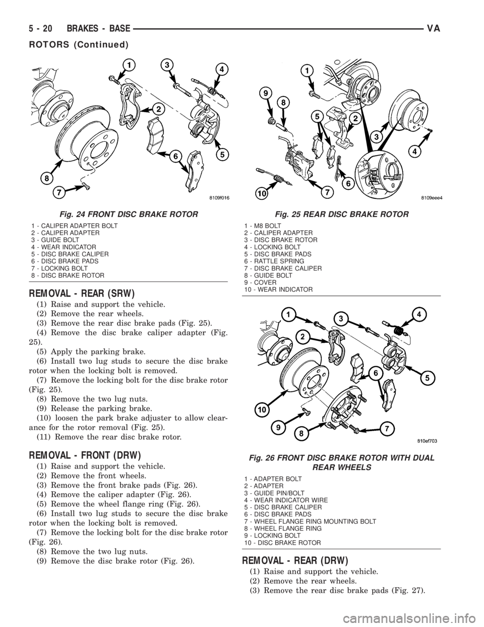
(1) Raise and support the vehicle.
(2) Remove the rear wheels.
(3) Remove the rear disc brake pads (Fig. 25).
(4) Remove the disc brake caliper adapter (Fig.
25).
(5) Apply the parking brake.
(6) Install two lug studs to secure the disc brake
rotor when the locking bolt is removed.
(7) Remove the locking bolt for the disc brake rotor
(Fig. 25).
(8) Remove the two lug nuts.
(9) Release the parking brake.
(10) loosen the park brake adjuster to allow clear-
ance for the rotor removal (Fig. 25).
(11) Remove the rear disc brake rotor.
REMOVAL - FRONT (DRW)
(1) Raise and support the vehicle.
(2) Remove the front wheels.
(3) Remove the front brake pads (Fig. 26).
(4) Remove the caliper adapter (Fig. 26).
(5) Remove the wheel flange ring (Fig. 26).
(6) Install two lug studs to secure the disc brake
rotor when the locking bolt is removed.
(7) Remove the locking bolt for the disc brake rotor
(Fig. 26).
(8) Remove the two lug nuts.
(9) Remove the disc brake rotor (Fig. 26).
REMOVAL - REAR (DRW)
(1) Raise and support the vehicle.
(2) Remove the rear wheels.
(3) Remove the rear disc brake pads (Fig. 27).
Fig. 24 FRONT DISC BRAKE ROTOR
1 - CALIPER ADAPTER BOLT
2 - CALIPER ADAPTER
3 - GUIDE BOLT
4 - WEAR INDICATOR
5 - DISC BRAKE CALIPER
6 - DISC BRAKE PADS
7 - LOCKING BOLT
8 - DISC BRAKE ROTOR
Fig. 25 REAR DISC BRAKE ROTOR
1-M8BOLT
2 - CALIPER ADAPTER
3 - DISC BRAKE ROTOR
4 - LOCKING BOLT
5 - DISC BRAKE PADS
6 - RATTLE SPRING
7 - DISC BRAKE CALIPER
8 - GUIDE BOLT
9 - COVER
10 - WEAR INDICATOR
Fig. 26 FRONT DISC BRAKE ROTOR WITH DUAL
REAR WHEELS
1 - ADAPTER BOLT
2 - ADAPTER
3 - GUIDE PIN/BOLT
4 - WEAR INDICATOR WIRE
5 - DISC BRAKE CALIPER
6 - DISC BRAKE PADS
7 - WHEEL FLANGE RING MOUNTING BOLT
8 - WHEEL FLANGE RING
9 - LOCKING BOLT
10 - DISC BRAKE ROTOR
5 - 20 BRAKES - BASEVA
ROTORS (Continued)
Page 85 of 1232
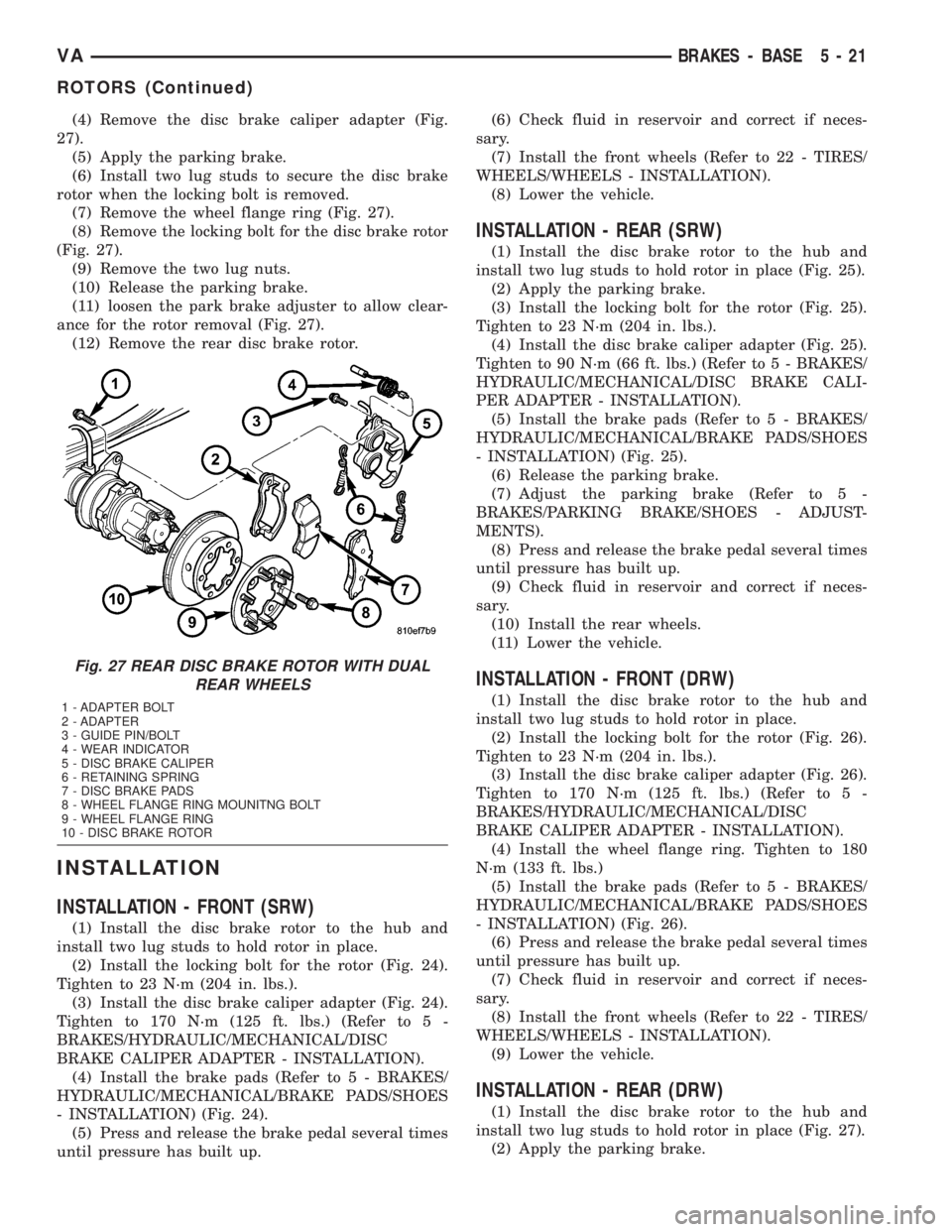
(4) Remove the disc brake caliper adapter (Fig.
27).
(5) Apply the parking brake.
(6) Install two lug studs to secure the disc brake
rotor when the locking bolt is removed.
(7) Remove the wheel flange ring (Fig. 27).
(8) Remove the locking bolt for the disc brake rotor
(Fig. 27).
(9) Remove the two lug nuts.
(10) Release the parking brake.
(11) loosen the park brake adjuster to allow clear-
ance for the rotor removal (Fig. 27).
(12) Remove the rear disc brake rotor.
INSTALLATION
INSTALLATION - FRONT (SRW)
(1) Install the disc brake rotor to the hub and
install two lug studs to hold rotor in place.
(2) Install the locking bolt for the rotor (Fig. 24).
Tighten to 23 N´m (204 in. lbs.).
(3) Install the disc brake caliper adapter (Fig. 24).
Tighten to 170 N´m (125 ft. lbs.) (Refer to 5 -
BRAKES/HYDRAULIC/MECHANICAL/DISC
BRAKE CALIPER ADAPTER - INSTALLATION).
(4) Install the brake pads (Refer to 5 - BRAKES/
HYDRAULIC/MECHANICAL/BRAKE PADS/SHOES
- INSTALLATION) (Fig. 24).
(5) Press and release the brake pedal several times
until pressure has built up.(6) Check fluid in reservoir and correct if neces-
sary.
(7) Install the front wheels (Refer to 22 - TIRES/
WHEELS/WHEELS - INSTALLATION).
(8) Lower the vehicle.
INSTALLATION - REAR (SRW)
(1) Install the disc brake rotor to the hub and
install two lug studs to hold rotor in place (Fig. 25).
(2) Apply the parking brake.
(3) Install the locking bolt for the rotor (Fig. 25).
Tighten to 23 N´m (204 in. lbs.).
(4) Install the disc brake caliper adapter (Fig. 25).
Tighten to 90 N´m (66 ft. lbs.) (Refer to 5 - BRAKES/
HYDRAULIC/MECHANICAL/DISC BRAKE CALI-
PER ADAPTER - INSTALLATION).
(5) Install the brake pads (Refer to 5 - BRAKES/
HYDRAULIC/MECHANICAL/BRAKE PADS/SHOES
- INSTALLATION) (Fig. 25).
(6) Release the parking brake.
(7) Adjust the parking brake (Refer to 5 -
BRAKES/PARKING BRAKE/SHOES - ADJUST-
MENTS).
(8) Press and release the brake pedal several times
until pressure has built up.
(9) Check fluid in reservoir and correct if neces-
sary.
(10) Install the rear wheels.
(11) Lower the vehicle.
INSTALLATION - FRONT (DRW)
(1) Install the disc brake rotor to the hub and
install two lug studs to hold rotor in place.
(2) Install the locking bolt for the rotor (Fig. 26).
Tighten to 23 N´m (204 in. lbs.).
(3) Install the disc brake caliper adapter (Fig. 26).
Tighten to 170 N´m (125 ft. lbs.) (Refer to 5 -
BRAKES/HYDRAULIC/MECHANICAL/DISC
BRAKE CALIPER ADAPTER - INSTALLATION).
(4) Install the wheel flange ring. Tighten to 180
N´m (133 ft. lbs.)
(5) Install the brake pads (Refer to 5 - BRAKES/
HYDRAULIC/MECHANICAL/BRAKE PADS/SHOES
- INSTALLATION) (Fig. 26).
(6) Press and release the brake pedal several times
until pressure has built up.
(7) Check fluid in reservoir and correct if neces-
sary.
(8) Install the front wheels (Refer to 22 - TIRES/
WHEELS/WHEELS - INSTALLATION).
(9) Lower the vehicle.
INSTALLATION - REAR (DRW)
(1) Install the disc brake rotor to the hub and
install two lug studs to hold rotor in place (Fig. 27).
(2) Apply the parking brake.
Fig. 27 REAR DISC BRAKE ROTOR WITH DUAL
REAR WHEELS
1 - ADAPTER BOLT
2 - ADAPTER
3 - GUIDE PIN/BOLT
4 - WEAR INDICATOR
5 - DISC BRAKE CALIPER
6 - RETAINING SPRING
7 - DISC BRAKE PADS
8 - WHEEL FLANGE RING MOUNITNG BOLT
9 - WHEEL FLANGE RING
10 - DISC BRAKE ROTOR
VABRAKES - BASE 5 - 21
ROTORS (Continued)
Page 110 of 1232
(6) Properly align the radiator assembly and
install the front end cross member.
(7) Connect negative battery cable.
ENGINE BLOCK HEATER
REMOVAL
WARNING: RISK OF INJURY TO SKIN AND EYES
DUE TO SCALDING FROM HOT COOLANT. DO NOT
OPEN THE COOLING SYSTEM UNLESS THE TEM-
PERATURE IS BELOW 194ÉF (90ÉC). WEAR PRO-
TECTIVE CLOTHING AND EYE WEAR. RISK OF
POISONING IF COOLANT IS SWALLOWED. STORE
COOLANT IN PROPER AND APPROPRIATELY
MARKED CONTAINERS.
(1) Disconnect the negative battery cable.
(2) Drain the cooling system.
(3) Record the location and snip the wire ties.
(4) Unscrew the engine block heater from the core
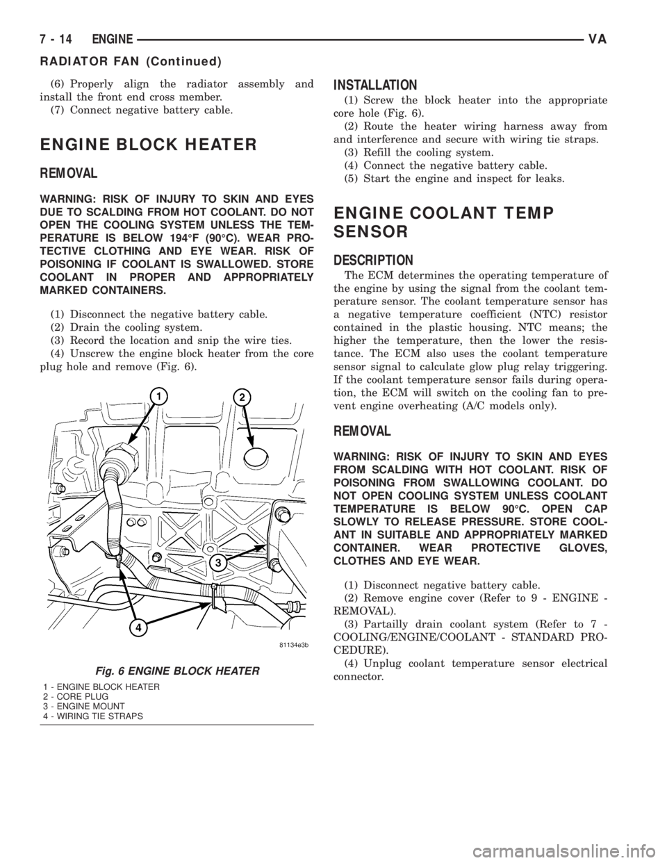
plug hole and remove (Fig. 6).
INSTALLATION
(1) Screw the block heater into the appropriate
core hole (Fig. 6).
(2) Route the heater wiring harness away from
and interference and secure with wiring tie straps.
(3) Refill the cooling system.
(4) Connect the negative battery cable.
(5) Start the engine and inspect for leaks.
ENGINE COOLANT TEMP
SENSOR
DESCRIPTION
The ECM determines the operating temperature of
the engine by using the signal from the coolant tem-
perature sensor. The coolant temperature sensor has
a negative temperature coefficient (NTC) resistor
contained in the plastic housing. NTC means; the
higher the temperature, then the lower the resis-
tance. The ECM also uses the coolant temperature
sensor signal to calculate glow plug relay triggering.
If the coolant temperature sensor fails during opera-
tion, the ECM will switch on the cooling fan to pre-
vent engine overheating (A/C models only).
REMOVAL
WARNING: RISK OF INJURY TO SKIN AND EYES
FROM SCALDING WITH HOT COOLANT. RISK OF
POISONING FROM SWALLOWING COOLANT. DO
NOT OPEN COOLING SYSTEM UNLESS COOLANT
TEMPERATURE IS BELOW 90ÉC. OPEN CAP
SLOWLY TO RELEASE PRESSURE. STORE COOL-
ANT IN SUITABLE AND APPROPRIATELY MARKED
CONTAINER. WEAR PROTECTIVE GLOVES,
CLOTHES AND EYE WEAR.
(1) Disconnect negative battery cable.
(2) Remove engine cover (Refer to 9 - ENGINE -
REMOVAL).
(3) Partailly drain coolant system (Refer to 7 -
COOLING/ENGINE/COOLANT - STANDARD PRO-
CEDURE).
(4) Unplug coolant temperature sensor electrical
connector.
Fig. 6 ENGINE BLOCK HEATER
1 - ENGINE BLOCK HEATER
2 - CORE PLUG
3 - ENGINE MOUNT
4 - WIRING TIE STRAPS
7 - 14 ENGINEVA
RADIATOR FAN (Continued)
Page 121 of 1232
ELECTRONIC CONTROL MODULES
TABLE OF CONTENTS
page page
CENTRAL TIMER MODULE
DESCRIPTION..........................1
OPERATION............................2
DIAGNOSIS AND TESTING - CENTRAL TIMER
MODULE.............................2
REMOVAL.............................2
INSTALLATION..........................2
CONTROLLER ANTILOCK BRAKE
DESCRIPTION..........................3
REMOVAL.............................3INSTALLATION..........................3
ENGINE CONTROL MODULE
DESCRIPTION..........................3
REMOVAL.............................4
INSTALLATION..........................4
TRANSMISSION CONTROL MODULE
DESCRIPTION..........................5
OPERATION............................5
STANDARD PROCEDURE - TCM ADAPTATION . 8
CENTRAL TIMER MODULE
DESCRIPTION
The central timer module (CTM) is located beneath
the driver seat. The CTM uses information carried on
the programmable communications interface (PCI)
data bus network along with many hard wired inputs
to monitor many sensor and switch inputs. In
response to those inputs, the circuitry and program-
ming of the CTM allow it to supply the vehicle occu-
pants with audible and visual information, and to
control and integrate many functions and features of
the vehicle through both hard wired outputs and the
transmission of message outputs to other modules in
the vehicle over the PCI data bus.
The features that the CTM supports or controls
include the following:
²Central Locking- The CTM on vehicles
equipped with the optional Vehicle Theft Security
System (VTSS) includes a central locking/unlocking
feature.
²Enhanced Accident Response- The CTM pro-
vides an optional enhanced accident response fea-
ture. This is a programmable feature.
²Panic Mode- The CTM provides support for
the optional RKE system panic mode including horn,
headlamp, and park lamp flash features.
²Power Lock Control- The CTM provides the
optional power lock system features, including sup-
port for the automatic door lock and door lock inhibit
modes.²Programmable Features- The CTM provides
support for certain programmable features.
²Remote Keyless Entry- The CTM provides
the optional Remote Keyless Entry (RKE) system fea-
tures, including support for the RKE Lock (with
optional horn and park lamps flash), Unlock (with
park lamps flash, driver-door-only unlock, and
unlock-all-doors), Panic, and illuminated entry
modes, as well as the ability to be programmed to
recognize up to four RKE transmitters. The RKE
horn, driver-door-only unlock, and unlock-all-doors
features are programmable.
²Vehicle Theft Security System- The CTM
provides control of the optional Vehicle Theft Secu-
rity System (VTSS) features, including support for
the central locking/unlocking mode and control of the
Security indicator in the instrument cluster.
Hard wired circuitry connects the CTM to the elec-
trical system of the vehicle. Refer to the appropriate
wiring information.
Many of the features in the vehicle controlled or
supported by the CTM are programmable using the
DRBIIItscan tool. However, if any of the CTM hard-
ware components are damaged or faulty, the entire
CTM unit must be replaced. The hard wired inputs
or outputs of all CTM versions can be diagnosed
using conventional diagnostic tools and methods;
however, for diagnosis of the CTM or the PCI data
bus, the use of a DRBIIItscan tool is required. Refer
to the appropriate diagnostic information.
VAELECTRONIC CONTROL MODULES 8E - 1
Page 122 of 1232
OPERATION
The central timer module (CTM) monitors many
hard wired switch and sensor inputs as well as those
resources it shares with other modules in the vehicle
through its communication over the programmable
communications interface (PCI) data bus network.
The internal programming and all of these inputs
allow the CTM to determine the tasks it needs to
perform and their priorities, as well as both the stan-
dard and optional features that it should provide.
The CTM then performs those tasks and provides
those features through both PCI data bus communi-
cation with other modules and hard wired outputs
through a number of driver circuits, relays, and
actuators.These outputs allow the CTM the ability to
control numerous accessory systems in the vehicle.
The CTM monitors its own internal circuitry as
well as many of its input and output circuits, and
will store a Diagnostic Trouble Code (DTC) in elec-
tronic memory for any failure it detects. These DTCs
can be retrieved and diagnosed using a DRBIIItscan
tool. Refer to the appropriate diagnostic information.
HARD WIRED INPUTS
The hard wired inputs to the CTM include the fol-
lowing:
²Fused B(+)
²Fused ignition switch output (run-acc)
²Fused ignition switch output (run-start)
²Ground
²Key-in ignition switch sense
²Sliding door switch sense
²Passenger door switch sense
²Driver door switch sense
²PCI bus circuit
HARD WIRED OUTPUTS
The hard wired outputs of the CTM include the fol-
lowing:
²Door lock relay output
²Door unlock relay output
²VTSS indicator driver
MESSAGING
The CTM uses the following messages received
from other electronic modules over the PCI data bus:
²Airbag Deploy (ACM)
²Beep request (CMTC)
²Charging System Failure (PCM)
²Chime request (EMIC)
²Engine RPM (PCM)
²OK to Arm VTSS (PCM)
²Security indicator request (SKIM)
²System Voltage (PCM)
²Valid/Invalid Key (SKIM)
²Vehicle Distance (PCM)²Vehicle Speed (PCM)DIAGNOSIS AND TESTING - CENTRAL TIMER
MODULE
WARNING: ON VEHICLES EQUIPPED WITH AIR-
BAGS, DISABLE THE AIRBAG SYSTEM BEFORE
ATTEMPTING ANY STEERING WHEEL, STEERING
COLUMN, SEAT BELT TENSIONER, OR INSTRU-
MENT PANEL COMPONENT DIAGNOSIS OR SER-
VICE. DISCONNECT AND ISOLATE THE BATTERY
NEGATIVE (GROUND) CABLE, THEN WAIT TWO
MINUTES FOR THE AIRBAG SYSTEM CAPACITOR
TO DISCHARGE BEFORE PERFORMING FURTHER
DIAGNOSIS OR SERVICE. THIS IS THE ONLY SURE
WAY TO DISABLE THE AIRBAG SYSTEM. FAILURE
TO TAKE THE PROPER PRECAUTIONS COULD
RESULT IN ACCIDENTAL AIRBAG DEPLOYMENT
AND POSSIBLE PERSONAL INJURY.
The hard wired inputs to and outputs from the
central timer module (CTM) may be diagnosed and
tested using conventional diagnostic tools and meth-
ods. Refer to the appropriate wiring information.
However, conventional diagnostic methods may not
prove conclusive in the diagnosis of the CTM. In
order to obtain conclusive testing of the CTM, the
programmable communications interface (PCI) data
bus network and all of the modules that provide
inputs to or receive outputs from the CTM must also
be checked. The most reliable, efficient, and accurate
means to diagnose the CTM, the PCI data bus net-
work, and the modules that provide inputs to, or
receive outputs from, the CTM requires the use of a
DRBIIItscan tool. Refer to the appropriate diagnos-
tic information.
REMOVAL
(1) Disconnect and isolate the battery negative
cable.
(2) Slide the driver seat to the full forward posi-
tion.
(3) Disconnect the wire harness connector for the
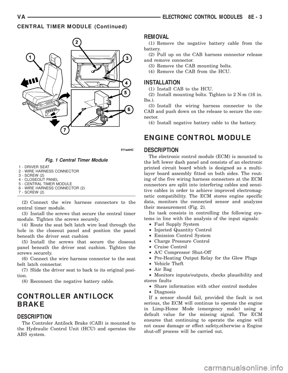
seat belt latch. (Fig. 1).
(4) Remove the screws that secure the closeout
panel beneathe the driver seat cushion and remove
the panel.
(5) Remove the screws that secure the central
timer module to the bracket.
(6) Disconnect the wire harness connectors from
the central timer module.
(7) Remove the central timer module from the
vehicle.
INSTALLATION
(1) Position the central timer module in the vehicle
8E - 2 ELECTRONIC CONTROL MODULESVA
CENTRAL TIMER MODULE (Continued)
Page 123 of 1232
(2) Connect the wire harness connectors to the
central timer module.
(3) Install the screws that secure the central timer
module. Tighten the screws securely.
(4) Route the seat belt latch wire lead through the
hole in the closeout panel and position the panel
beneath the driver seat cushion
(5) Install the screws that secure the closeout
panel beneath the driver seat cushion. Tighten the
screws securely.
(6) Connect the wire harness connector to the seat
belt latch connector.
(7) Slide the driver seat to back to its original posi-
tion.
(8) Reconnect the negative battery cable.
CONTROLLER ANTILOCK
BRAKE
DESCRIPTION
The Controler Antilock Brake (CAB) is mounted to
the Hydraulic Control Unit (HCU) and operates the
ABS system.
REMOVAL
(1) Remove the negative battery cable from the
battery.
(2) Pull up on the CAB harness connector release
and remove connector.
(3) Remove the CAB mounting bolts.
(4) Remove the CAB from the HCU.
INSTALLATION
(1) Install CAB to the HCU.
(2) Install mounting bolts. Tighten to 2 N´m (16 in.
lbs.).
(3) Install the wiring harness connector to the
CAB and push down on the release to secure the con-
nector.
(4) Install negative battery cable to the battery.
ENGINE CONTROL MODULE
DESCRIPTION
The electronic control module (ECM) is mounted to
the left lower dash panel and consists of an electronic
printed circuit board which is designed as a multi-
layer board assembly fitted on both sides. The rout-
ing of the five wiring harness connectors at the ECM
connectors are split into interfering cables and sensi-
tive cables in order to achieve improved electromag-
netic compatibility. The ECM stores engine specific
data, monitors the connected sensor and analyzes
their measurement (Fig. 2).
Its task consists in controlling the following sys-
tems in line with the analysis of the input signals:
²Fuel Supply System
²Injected Quantity Control
²Emission Control System
²Charge Pressure Control
²Cruise Control
²A/C Compressor Shut-Off
²Pre-Heating Output Relay for the Glow Plugs
²Vehicle Theft
²Air Bag
²Monitors inputs/outputs, checks plausibility and
stores faults
²Share information with other control modules
²Diagnosis
If a sensor should fail, provided the fault is not
serious, the ECM will continue to operate the engine
in Limp-Home Mode (emergency mode) using a
default value for the missing signal. The ECM
ensures that continuing to operate the engine will
not cause damage or effect safety,otherwise a Engine
shut-off process will be carried out.Fig. 1 Central Timer Module
1 - DRIVER SEAT
2 - WIRE HARNESS CONNECTOR
3 - SCREW (2)
4 - CLOSEOUT PANEL
5 - CENTRAL TIMER MODULE
6 - WIRE HARNESS CONNECTOR (2)
7 - SCREW (2)
VAELECTRONIC CONTROL MODULES 8E - 3
CENTRAL TIMER MODULE (Continued)
Page 130 of 1232

²Battery Holddown- The battery holddown
hardware secures the battery in the battery tray in
the engine compartment.
²Battery Tray- The battery tray provides a
secure mounting location in the vehicle for the bat-
tery and an anchor point for the battery holddown
hardware.
For battery system maintenance schedules and
jump starting procedures, see the owner's manual in
the vehicle glove box. Optionally, refer to the Lubri-
cation and Maintenance section of this manual for
the recommended battery maintenance schedules and
for the proper battery jump starting procedure. While
battery charging can be considered a maintenance
procedure, the battery charging procedure and
related information are located later in this section of
this service manual. This was done because the bat-
tery must be fully-charged before any battery system
diagnosis or testing procedures can be performed.
OPERATION
The battery system is designed to provide a safe,
efficient, reliable and mobile means of delivering and
storing electrical energy. This electrical energy is
required to operate the engine starting system, as
well as to operate many of the other vehicle acces-
sory systems for limited durations while the engine
and/or the charging system are not operating. The
battery system is also designed to provide a reserve
of electrical energy to supplement the charging sys-
tem for short durations while the engine is running
and the electrical current demands of the vehicle
exceed the output of the charging system. In addition
to delivering, and storing electrical energy for the
vehicle, the battery system serves as a capacitor and
voltage stabilizer for the vehicle electrical system. It
absorbs most abnormal or transient voltages caused
by the switching of any of the electrical components
or circuits in the vehicle.
DIAGNOSIS AND TESTING - BATTERY SYSTEM
The battery, starting, and charging systems in the
vehicle operate with one another and must be testedas a complete system. In order for the engine to start
and the battery to maintain its charge properly, all of
the components that are used in these systems must
perform within specifications. It is important that
the battery, starting, and charging systems be thor-
oughly tested and inspected any time a battery needs
to be charged or replaced. The cause of abnormal bat-
tery discharge, overcharging or early battery failure
must be diagnosed and corrected before a battery is
replaced and before a vehicle is returned to service.
The service information for these systems has been
separated within this service manual to make it eas-
ier to locate the specific information you are seeking.
However, when attempting to diagnose any of these
systems, it is important that you keep their interde-
pendency in mind.
The diagnostic procedures used for the battery,
starting, and charging systems include the most
basic conventional diagnostic methods, to the more
sophisticated On-Board Diagnostics (OBD) built into
the Powertrain Control Module (PCM). Use of an
induction-type milliampere ammeter, a volt/ohmme-
ter, a battery charger, a carbon pile rheostat (load
tester) and a 12-volt test lamp may be required. All
OBD-sensed systems are monitored by the PCM.
Each monitored circuit is assigned a Diagnostic Trou-
ble Code (DTC). The PCM will store a DTC in elec-
tronic memory for any failure it detects. Refer to
Charging System for the proper charging system on-
board diagnostic test procedures.
MICRO 420 BATTERY TESTER
The Micro 420 automotive battery tester is
designed to help the dealership technicians diagnose
the cause of a defective battery. Follow the instruc-
tion manual supplied with the tester to properly
diagnose a vehicle. If the instruction manual is not
available refer to the standard procedure in this sec-
tion, which includes the directions for using the
Micro 420 battery tester.
8F - 2 BATTERY SYSTEMVA
BATTERY SYSTEM (Continued)
Page 138 of 1232
STANDARD PROCEDURE - OPEN-CIRCUIT
VOLTAGE TEST
A battery open-circuit voltage (no load) test will
show the approximate state-of-charge of a battery.
This test can be used in place of the hydrometer test
when a hydrometer is not available, or for mainte-
nance-free batteries with non-removable cell caps.
Before proceeding with this test, completely charge
the battery (Refer to 8 - ELECTRICAL/BATTERY
SYSTEM/BATTERY - STANDARD PROCEDURE).
(1) Before measuring the open-circuit voltage, the
surface charge must be removed from the battery.
Turn on the headlamps for fifteen seconds, then
allow up to five minutes for the battery voltage to
stabilize.
(2) Disconnect and isolate both battery cables, neg-
ative cable first.
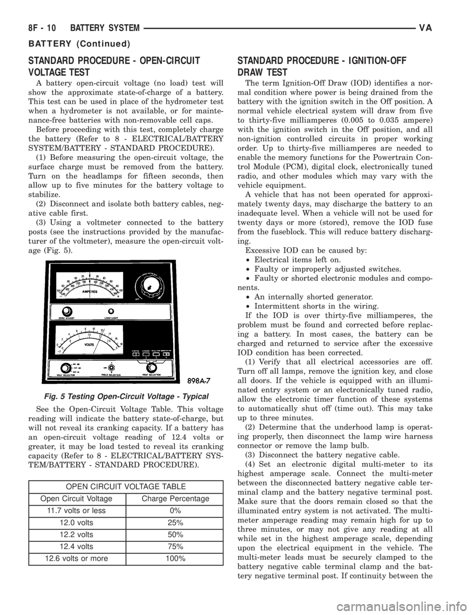
(3) Using a voltmeter connected to the battery
posts (see the instructions provided by the manufac-
turer of the voltmeter), measure the open-circuit volt-
age (Fig. 5).
See the Open-Circuit Voltage Table. This voltage
reading will indicate the battery state-of-charge, but
will not reveal its cranking capacity. If a battery has
an open-circuit voltage reading of 12.4 volts or
greater, it may be load tested to reveal its cranking
capacity (Refer to 8 - ELECTRICAL/BATTERY SYS-
TEM/BATTERY - STANDARD PROCEDURE).
OPEN CIRCUIT VOLTAGE TABLE
Open Circuit Voltage Charge Percentage
11.7 volts or less 0%
12.0 volts 25%
12.2 volts 50%
12.4 volts 75%
12.6 volts or more 100%
STANDARD PROCEDURE - IGNITION-OFF
DRAW TEST
The term Ignition-Off Draw (IOD) identifies a nor-
mal condition where power is being drained from the
battery with the ignition switch in the Off position. A
normal vehicle electrical system will draw from five
to thirty-five milliamperes (0.005 to 0.035 ampere)
with the ignition switch in the Off position, and all
non-ignition controlled circuits in proper working
order. Up to thirty-five milliamperes are needed to
enable the memory functions for the Powertrain Con-
trol Module (PCM), digital clock, electronically tuned
radio, and other modules which may vary with the
vehicle equipment.
A vehicle that has not been operated for approxi-
mately twenty days, may discharge the battery to an
inadequate level. When a vehicle will not be used for
twenty days or more (stored), remove the IOD fuse
from the fuseblock. This will reduce battery discharg-
ing.
Excessive IOD can be caused by:
²Electrical items left on.
²Faulty or improperly adjusted switches.
²Faulty or shorted electronic modules and compo-
nents.
²An internally shorted generator.
²Intermittent shorts in the wiring.
If the IOD is over thirty-five milliamperes, the
problem must be found and corrected before replac-
ing a battery. In most cases, the battery can be
charged and returned to service after the excessive
IOD condition has been corrected.
(1) Verify that all electrical accessories are off.
Turn off all lamps, remove the ignition key, and close
all doors. If the vehicle is equipped with an illumi-
nated entry system or an electronically tuned radio,
allow the electronic timer function of these systems
to automatically shut off (time out). This may take
up to three minutes.
(2) Determine that the underhood lamp is operat-
ing properly, then disconnect the lamp wire harness
connector or remove the lamp bulb.
(3) Disconnect the battery negative cable.
(4) Set an electronic digital multi-meter to its
highest amperage scale. Connect the multi-meter
between the disconnected battery negative cable ter-
minal clamp and the battery negative terminal post.
Make sure that the doors remain closed so that the
illuminated entry system is not activated. The multi-
meter amperage reading may remain high for up to
three minutes, or may not give any reading at all
while set in the highest amperage scale, depending
upon the electrical equipment in the vehicle. The
multi-meter leads must be securely clamped to the
battery negative cable terminal clamp and the bat-
tery negative terminal post. If continuity between the
Fig. 5 Testing Open-Circuit Voltage - Typical
8F - 10 BATTERY SYSTEMVA
BATTERY (Continued)