2005 MERCEDES-BENZ SPRINTER ECU
[x] Cancel search: ECUPage 180 of 1232
²ABS Lamp-On Message- Each time the clus-
ter receives a lamp-on message from the CAB, the
ABS indicator will be illuminated. The indicator
remains illuminated until the cluster receives a
lamp-off message from the CAB, or until the ignition
switch is turned to the Off position, whichever occurs
first.
The CAB continually monitors the ABS and EBV
circuits and sensors to decide whether the systems
are in good operating condition. The CAB then sends
the proper lamp-on or lamp-off messages to the
instrument cluster. If the CAB sends a lamp-on mes-
sage after the bulb test, it indicates that the CAB
has detected a system malfunction and/or that the
ABS or EBV systems have become inoperative. The
CAB will store a Diagnostic Trouble Code (DTC) for
any malfunction it detects. For proper diagnosis of
the ABS and EBV systems, the CAB, the CAN data
bus, the electronic message inputs to the instrument
cluster, or the instrument cluster circuitry that con-
trols the ABS indicator, a DRBIIItscan tool is
required. Refer to the appropriate diagnostic infor-
mation.
AIRBAG INDICATOR
DESCRIPTION
An airbag indicator is standard equipment on all
instrument clusters. The airbag indicator is located
near the left edge of the instrument cluster, next to
the tachometer. The airbag indicator consists of a
stencil-like cutout of the letters ªSRSº in the opaque
layer of the instrument cluster overlay. The dark
outer layer of the overlay prevents the indicator from
being clearly visible when it is not illuminated. A red
Light Emitting Diode (LED) behind the cutout in the
opaque layer of the overlay causes the ªSRSº text to
appear in red through the translucent outer layer of
the overlay when the indicator is illuminated from
behind by the LED, which is soldered onto the
instrument cluster electronic circuit board. The air-
bag indicator is serviced as a unit with the instru-
ment cluster.
OPERATION
The airbag (SRS) indicator gives an indication to
the vehicle operator when the Airbag Control Module
(ACM) has recorded a Diagnostic Trouble Code (DTC)
for a Supplemental Restraint System (SRS) circuit or
component malfunction. Such a DTC may indicate
that the SRS is faulty or inoperative. The airbag
indicator is controlled by a transistor on the instru-
ment cluster circuit board based upon cluster pro-
gramming and a hard wired input received by the
cluster from the ACM. The airbag indicator LightEmitting Diode (LED) is completely controlled by the
instrument cluster logic circuit, and that logic will
only allow this indicator to operate when the instru-
ment cluster detects that the ignition switch is in the
On position. Therefore, the LED will always be off
when the ignition switch is in any position except
On. The LED only illuminates when it is provided a
path to ground by the instrument cluster transistor.
The instrument cluster will turn on the airbag indi-
cator for the following reasons:
²Bulb Test- Each time the ignition switch is
turned to the On position the airbag indicator is illu-
minated for about four seconds. The entire four sec-
ond bulb test is a function of the ACM.
²Airbag Lamp-On Input- Each time the cluster
receives a lamp-on input from the ACM, the airbag
indicator will be illuminated. The indicator can be
flashed on and off, or illuminated solid, as dictated
by the ACM input. For some DTC's, if the problem
does not recur, the ACM will send a lamp-off input
automatically. Other DTC's may require that a fault
be repaired and the ACM be reset before a lamp-off
input will be sent. For more information on the ACM
and the DTC set and reset parameters, refer to 8 -
ELECTRICAL/RESTRAINTS/AIRBAG CONTROL
MODULE - OPERATION). The indicator remains
illuminated until the cluster receives a lamp-off
input from the ACM, or until the ignition switch is
turned to the Off position, whichever occurs first.
²Airbag Indicator Malfunction- Following the
seatbelt reminder function, each time the cluster
detects a malfunction in the airbag (SRS) indicator or
the airbag indicator circuit, the cluster will flash the
seatbelt indicator on and off. The cluster will con-
tinue to flash the seatbelt indicator until the airbag
indicator circuit fault is resolved, or until the ignition
switch is turned to the Off position, whichever occurs
first.
The ACM continually monitors the SRS circuits
and sensors to decide whether the system is in good
operating condition. The ACM then provides the
proper lamp-on or lamp-off inputs to the instrument
cluster. If the ACM provides a lamp-on input after
the bulb test, it indicates that the ACM has detected
a system malfunction and/or that the airbags and
seat belt tensioners may not deploy when required,
or may deploy when not required. The ACM will
store a DTC for any malfunction it detects. The ACM
input circuit to the instrument cluster can be diag-
nosed using conventional diagnostic tools and meth-
ods. For proper diagnosis of the SRS, the ACM, or
the instrument cluster circuitry that controls the air-
bag indicator, a DRBIIItscan tool is required. Refer
to the appropriate diagnostic information.
8J - 10 INSTRUMENT CLUSTERVA
ABS INDICATOR (Continued)
Page 205 of 1232
BRAKE/PARK LAMP BULB
REMOVAL
(1) Disconnect and isolate the battery negative
cable.
(2) If the vehicle is so equipped, remove the trim
from the inside of the right or left rear corner pillar.
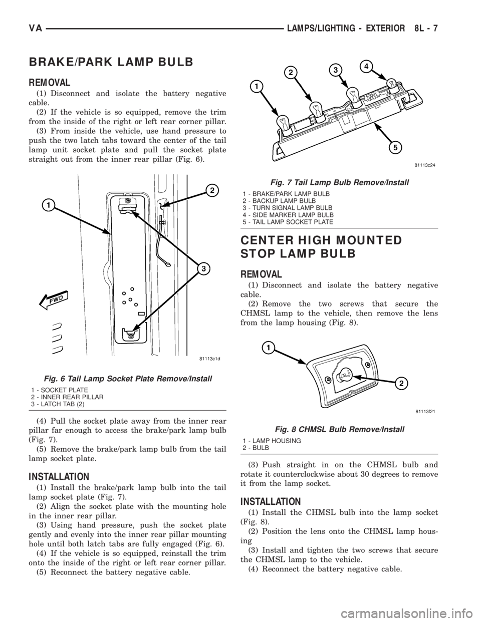
(3) From inside the vehicle, use hand pressure to
push the two latch tabs toward the center of the tail
lamp unit socket plate and pull the socket plate
straight out from the inner rear pillar (Fig. 6).
(4) Pull the socket plate away from the inner rear
pillar far enough to access the brake/park lamp bulb
(Fig. 7).
(5) Remove the brake/park lamp bulb from the tail
lamp socket plate.
INSTALLATION
(1) Install the brake/park lamp bulb into the tail
lamp socket plate (Fig. 7).
(2) Align the socket plate with the mounting hole
in the inner rear pillar.
(3) Using hand pressure, push the socket plate
gently and evenly into the inner rear pillar mounting
hole until both latch tabs are fully engaged (Fig. 6).
(4) If the vehicle is so equipped, reinstall the trim
onto the inside of the right or left rear corner pillar.
(5) Reconnect the battery negative cable.
CENTER HIGH MOUNTED
STOP LAMP BULB
REMOVAL
(1) Disconnect and isolate the battery negative
cable.
(2) Remove the two screws that secure the
CHMSL lamp to the vehicle, then remove the lens
from the lamp housing (Fig. 8).
(3) Push straight in on the CHMSL bulb and
rotate it counterclockwise about 30 degrees to remove
it from the lamp socket.
INSTALLATION
(1) Install the CHMSL bulb into the lamp socket
(Fig. 8).
(2) Position the lens onto the CHMSL lamp hous-
ing
(3) Install and tighten the two screws that secure
the CHMSL lamp to the vehicle.
(4) Reconnect the battery negative cable.
Fig. 6 Tail Lamp Socket Plate Remove/Install
1 - SOCKET PLATE
2 - INNER REAR PILLAR
3 - LATCH TAB (2)
Fig. 7 Tail Lamp Bulb Remove/Install
1 - BRAKE/PARK LAMP BULB
2 - BACKUP LAMP BULB
3 - TURN SIGNAL LAMP BULB
4 - SIDE MARKER LAMP BULB
5 - TAIL LAMP SOCKET PLATE
Fig. 8 CHMSL Bulb Remove/Install
1 - LAMP HOUSING
2 - BULB
VALAMPS/LIGHTING - EXTERIOR 8L - 7
Page 206 of 1232
CENTER HIGH MOUNTED
STOP LAMP UN
REMOVAL
(1) Disconnect and isolate the battery negative
cable.
(2) Remove the two screws that secure the
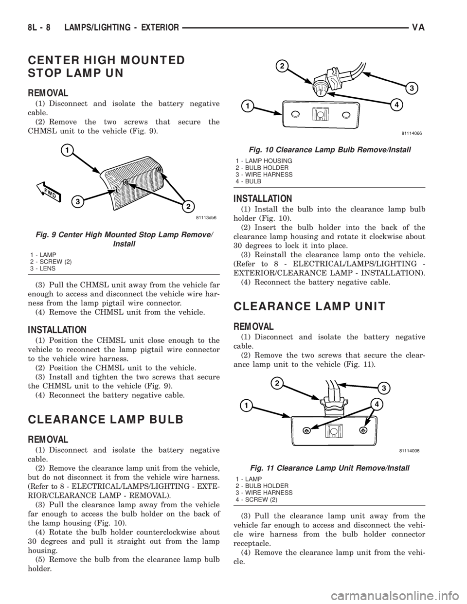
CHMSL unit to the vehicle (Fig. 9).
(3) Pull the CHMSL unit away from the vehicle far
enough to access and disconnect the vehicle wire har-
ness from the lamp pigtail wire connector.
(4) Remove the CHMSL unit from the vehicle.
INSTALLATION
(1) Position the CHMSL unit close enough to the
vehicle to reconnect the lamp pigtail wire connector
to the vehicle wire harness.
(2) Position the CHMSL unit to the vehicle.
(3) Install and tighten the two screws that secure
the CHMSL unit to the vehicle (Fig. 9).
(4) Reconnect the battery negative cable.
CLEARANCE LAMP BULB
REMOVAL
(1) Disconnect and isolate the battery negative
cable.
(2)
Remove the clearance lamp unit from the vehicle,
but do not disconnect it from the vehicle wire harness.
(Refer to 8 - ELECTRICAL/LAMPS/LIGHTING - EXTE-
RIOR/CLEARANCE LAMP - REMOVAL).
(3) Pull the clearance lamp away from the vehicle
far enough to access the bulb holder on the back of
the lamp housing (Fig. 10).
(4) Rotate the bulb holder counterclockwise about
30 degrees and pull it straight out from the lamp
housing.
(5) Remove the bulb from the clearance lamp bulb
holder.
INSTALLATION
(1) Install the bulb into the clearance lamp bulb
holder (Fig. 10).
(2) Insert the bulb holder into the back of the
clearance lamp housing and rotate it clockwise about
30 degrees to lock it into place.
(3) Reinstall the clearance lamp onto the vehicle.
(Refer to 8 - ELECTRICAL/LAMPS/LIGHTING -
EXTERIOR/CLEARANCE LAMP - INSTALLATION).
(4) Reconnect the battery negative cable.
CLEARANCE LAMP UNIT
REMOVAL
(1) Disconnect and isolate the battery negative
cable.
(2) Remove the two screws that secure the clear-
ance lamp unit to the vehicle (Fig. 11).
(3) Pull the clearance lamp unit away from the
vehicle far enough to access and disconnect the vehi-
cle wire harness from the bulb holder connector
receptacle.
(4) Remove the clearance lamp unit from the vehi-
cle.
Fig. 9 Center High Mounted Stop Lamp Remove/
Install
1 - LAMP
2 - SCREW (2)
3 - LENS
Fig. 10 Clearance Lamp Bulb Remove/Install
1 - LAMP HOUSING
2 - BULB HOLDER
3 - WIRE HARNESS
4 - BULB
Fig. 11 Clearance Lamp Unit Remove/Install
1 - LAMP
2 - BULB HOLDER
3 - WIRE HARNESS
4 - SCREW (2)
8L - 8 LAMPS/LIGHTING - EXTERIORVA
Page 207 of 1232
INSTALLATION
(1) Position the clearance lamp unit close enough
to the vehicle to reconnect the vehicle wire harness
to the bulb holder connector receptacle (Fig. 11).
(2) Position the clearance lamp unit to the vehicle.
(3) Install and tighten the two screws that secure
the clearance lamp unit to the vehicle.
(4) Reconnect the battery negative cable.
DAYTIME RUNNING LAMP
RELAY
REMOVAL
Daytime Running Lamps (DRL) are only used in
vehicles manufactured for the Canadian market,
where this is required equipment. On vehicles
equipped with DRL, a right and a left DRL relay are
each located in a dedicated connector of the vehicle
wire harness. Each connector is snapped into an
opening in a stamped sheet metal bracket which is
secured with screws within the driver side front seat
riser just beneath the seat riser cover panel.
WARNING: ON VEHICLES EQUIPPED WITH AIRBAGS,
DISABLE THE SUPPLEMENTAL RESTRAINT SYSTEM
BEFORE ATTEMPTING ANY STEERING WHEEL,
STEERING COLUMN, DRIVER AIRBAG, PASSENGER
AIRBAG, SEAT BELT TENSIONER, OR INSTRUMENT
PANEL COMPONENT DIAGNOSIS OR SERVICE. DIS-
CONNECT AND ISOLATE THE BATTERY NEGATIVE
(GROUND) CABLE, THEN WAIT TWO MINUTES FOR
THE SYSTEM CAPACITOR TO DISCHARGE BEFORE
PERFORMING FURTHER DIAGNOSIS OR SERVICE.
THIS IS THE ONLY SURE WAY TO DISABLE THE SUP-
PLEMENTAL RESTRAINT SYSTEM. FAILURE TO TAKE
THE PROPER PRECAUTIONS COULD RESULT IN
ACCIDENTAL AIRBAG DEPLOYMENT AND POSSIBLE
PERSONAL INJURY.
(1) Disconnect and isolate the battery negative
cable.
(2) Move the driver side front seat to its most for-
ward position for easiest access to the seat riser
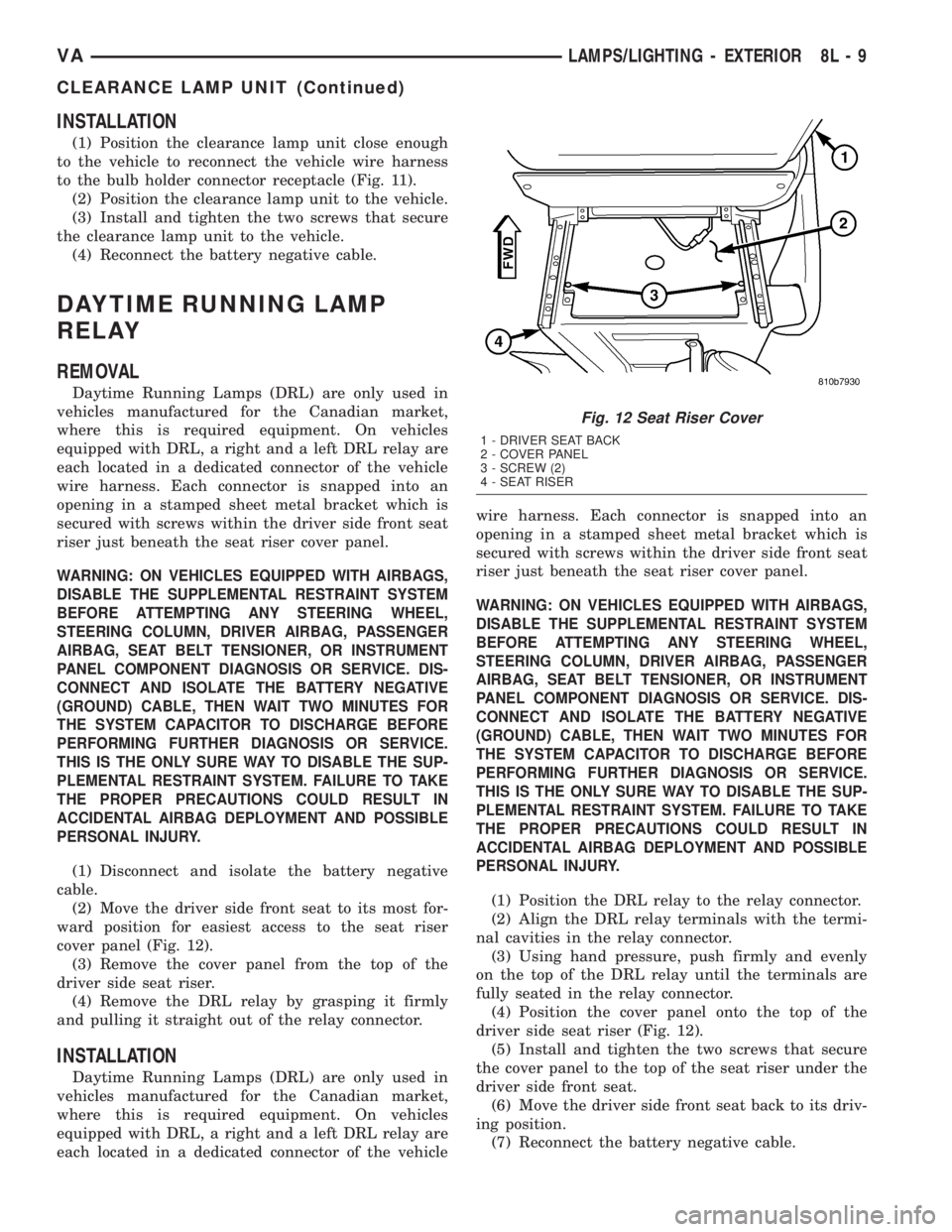
cover panel (Fig. 12).
(3) Remove the cover panel from the top of the
driver side seat riser.
(4) Remove the DRL relay by grasping it firmly
and pulling it straight out of the relay connector.
INSTALLATION
Daytime Running Lamps (DRL) are only used in
vehicles manufactured for the Canadian market,
where this is required equipment. On vehicles
equipped with DRL, a right and a left DRL relay are
each located in a dedicated connector of the vehiclewire harness. Each connector is snapped into an
opening in a stamped sheet metal bracket which is
secured with screws within the driver side front seat
riser just beneath the seat riser cover panel.
WARNING: ON VEHICLES EQUIPPED WITH AIRBAGS,
DISABLE THE SUPPLEMENTAL RESTRAINT SYSTEM
BEFORE ATTEMPTING ANY STEERING WHEEL,
STEERING COLUMN, DRIVER AIRBAG, PASSENGER
AIRBAG, SEAT BELT TENSIONER, OR INSTRUMENT
PANEL COMPONENT DIAGNOSIS OR SERVICE. DIS-
CONNECT AND ISOLATE THE BATTERY NEGATIVE
(GROUND) CABLE, THEN WAIT TWO MINUTES FOR
THE SYSTEM CAPACITOR TO DISCHARGE BEFORE
PERFORMING FURTHER DIAGNOSIS OR SERVICE.
THIS IS THE ONLY SURE WAY TO DISABLE THE SUP-
PLEMENTAL RESTRAINT SYSTEM. FAILURE TO TAKE
THE PROPER PRECAUTIONS COULD RESULT IN
ACCIDENTAL AIRBAG DEPLOYMENT AND POSSIBLE
PERSONAL INJURY.
(1) Position the DRL relay to the relay connector.
(2) Align the DRL relay terminals with the termi-
nal cavities in the relay connector.
(3) Using hand pressure, push firmly and evenly
on the top of the DRL relay until the terminals are
fully seated in the relay connector.
(4) Position the cover panel onto the top of the
driver side seat riser (Fig. 12).
(5) Install and tighten the two screws that secure
the cover panel to the top of the seat riser under the
driver side front seat.
(6) Move the driver side front seat back to its driv-
ing position.
(7) Reconnect the battery negative cable.
Fig. 12 Seat Riser Cover
1 - DRIVER SEAT BACK
2 - COVER PANEL
3 - SCREW (2)
4 - SEAT RISER
VALAMPS/LIGHTING - EXTERIOR 8L - 9
CLEARANCE LAMP UNIT (Continued)
Page 208 of 1232
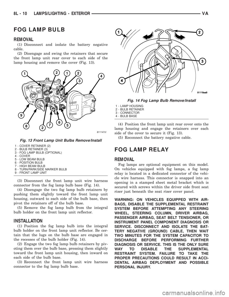
FOG LAMP BULB
REMOVAL
(1) Disconnect and isolate the battery negative
cable.
(2) Disengage and swing the retainers that secure
the front lamp unit rear cover to each side of the
lamp housing and remove the cover (Fig. 13).
(3) Disconnect the front lamp unit wire harness
connector from the fog lamp bulb base (Fig. 14).
(4) Disengage the two fog lamp bulb retainers by
pushing them slightly toward the front lamp unit
housing, outward to each side of the bulb base, then
pivot the retainers off of the bulb base.
(5) Remove the fog lamp bulb from the integral
bulb holder on the front lamp unit reflector.
INSTALLATION
(1) Position the fog lamp bulb into the integral
bulb holder on the front lamp unit reflector. Be cer-
tain that the lugs on the bulb base are engaged in
the recesses of the bulb holder (Fig. 14).
(2) Engage the two fog lamp bulb retainers by piv-
oting them over the bulb base, pressing them slightly
toward the front lamp unit housing, then inward on
each side of the bulb base.
(3) Reconnect the front lamp unit wire harness
connector to the fog lamp bulb base.(4) Position the front lamp unit rear cover onto the
lamp housing and engage the retainers over each
side of the cover to secure it (Fig. 13).
(5) Reconnect the battery negative cable.
FOG LAMP RELAY
REMOVAL
Fog lamps are optional equipment on this model.
On vehicles equipped with fog lamps, a fog lamp
relay is located in a dedicated connector of the vehi-
cle wire harness. This connector is snapped into an
opening in a stamped sheet metal bracket which is
secured with screws within the driver side front seat
riser just beneath the seat riser cover panel.
WARNING: ON VEHICLES EQUIPPED WITH AIR-
BAGS, DISABLE THE SUPPLEMENTAL RESTRAINT
SYSTEM BEFORE ATTEMPTING ANY STEERING
WHEEL, STEERING COLUMN, DRIVER AIRBAG,
PASSENGER AIRBAG, SEAT BELT TENSIONER, OR
INSTRUMENT PANEL COMPONENT DIAGNOSIS OR
SERVICE. DISCONNECT AND ISOLATE THE BAT-
TERY NEGATIVE (GROUND) CABLE, THEN WAIT
TWO MINUTES FOR THE SYSTEM CAPACITOR TO
DISCHARGE BEFORE PERFORMING FURTHER
DIAGNOSIS OR SERVICE. THIS IS THE ONLY SURE
WAY TO DISABLE THE SUPPLEMENTAL
RESTRAINT SYSTEM. FAILURE TO TAKE THE
PROPER PRECAUTIONS COULD RESULT IN ACCI-
DENTAL AIRBAG DEPLOYMENT AND POSSIBLE
PERSONAL INJURY.
Fig. 13 Front Lamp Unit Bulbs Remove/Install
1 - COVER RETAINER (2)
2 - BULB RETAINER (3)
3 - FOG LAMP BULB (OPTIONAL)
4 - COVER
5 - LOW BEAM BULB
6 - POSITION BULB
7 - HIGH BEAM BULB
8 - TURN/PARK/SIDE MARKER BULB
9 - FRONT LAMP UNIT
Fig. 14 Fog Lamp Bulb Remove/Install
1 - LAMP HOUSING
2 - BULB RETAINER
3 - CONNECTOR
4 - BULB BASE
8L - 10 LAMPS/LIGHTING - EXTERIORVA
Page 209 of 1232
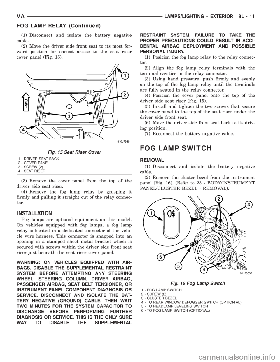
(1) Disconnect and isolate the battery negative
cable.
(2) Move the driver side front seat to its most for-
ward position for easiest access to the seat riser
cover panel (Fig. 15).
(3) Remove the cover panel from the top of the
driver side seat riser.
(4) Remove the fog lamp relay by grasping it
firmly and pulling it straight out of the relay connec-
tor.
INSTALLATION
Fog lamps are optional equipment on this model.
On vehicles equipped with fog lamps, a fog lamp
relay is located in a dedicated connector of the vehi-
cle wire harness. This connector is snapped into an
opening in a stamped sheet metal bracket which is
secured with screws within the driver side front seat
riser just beneath the seat riser cover panel.
WARNING: ON VEHICLES EQUIPPED WITH AIR-
BAGS, DISABLE THE SUPPLEMENTAL RESTRAINT
SYSTEM BEFORE ATTEMPTING ANY STEERING
WHEEL, STEERING COLUMN, DRIVER AIRBAG,
PASSENGER AIRBAG, SEAT BELT TENSIONER, OR
INSTRUMENT PANEL COMPONENT DIAGNOSIS OR
SERVICE. DISCONNECT AND ISOLATE THE BAT-
TERY NEGATIVE (GROUND) CABLE, THEN WAIT
TWO MINUTES FOR THE SYSTEM CAPACITOR TO
DISCHARGE BEFORE PERFORMING FURTHER
DIAGNOSIS OR SERVICE. THIS IS THE ONLY SURE
WAY TO DISABLE THE SUPPLEMENTALRESTRAINT SYSTEM. FAILURE TO TAKE THE
PROPER PRECAUTIONS COULD RESULT IN ACCI-
DENTAL AIRBAG DEPLOYMENT AND POSSIBLE
PERSONAL INJURY.
(1) Position the fog lamp relay to the relay connec-
tor.
(2) Align the fog lamp relay terminals with the
terminal cavities in the relay connector.
(3) Using hand pressure, push firmly and evenly
on the top of the fog lamp relay until the terminals
are fully seated in the relay connector.
(4) Position the cover panel onto the top of the
driver side seat riser (Fig. 15).
(5) Install and tighten the two screws that secure
the cover panel to the top of the seat riser under the
driver side front seat.
(6) Move the driver side front seat back to its driv-
ing position.
(7) Reconnect the battery negative cable.
FOG LAMP SWITCH
REMOVAL
(1) Disconnect and isolate the battery negative
cable.
(2) Remove the cluster bezel from the instrument
panel (Fig. 16). (Refer to 23 - BODY/INSTRUMENT
PANEL/CLUSTER BEZEL - REMOVAL).
Fig. 15 Seat Riser Cover
1 - DRIVER SEAT BACK
2 - COVER PANEL
3 - SCREW (2)
4 - SEAT RISER
Fig. 16 Fog Lamp Switch
1 - FOG LAMP SWITCH
2 - SCREW (2)
3 - CLUSTER BEZEL
4 - TO REAR WINDOW DEFOGGER SWITCH (OPTION AL)
5 - TO HEADLAMP LEVELING SWITCH
6 - TO FOG LAMP SWITCH (OPTIONAL)
VALAMPS/LIGHTING - EXTERIOR 8L - 11
FOG LAMP RELAY (Continued)
Page 210 of 1232
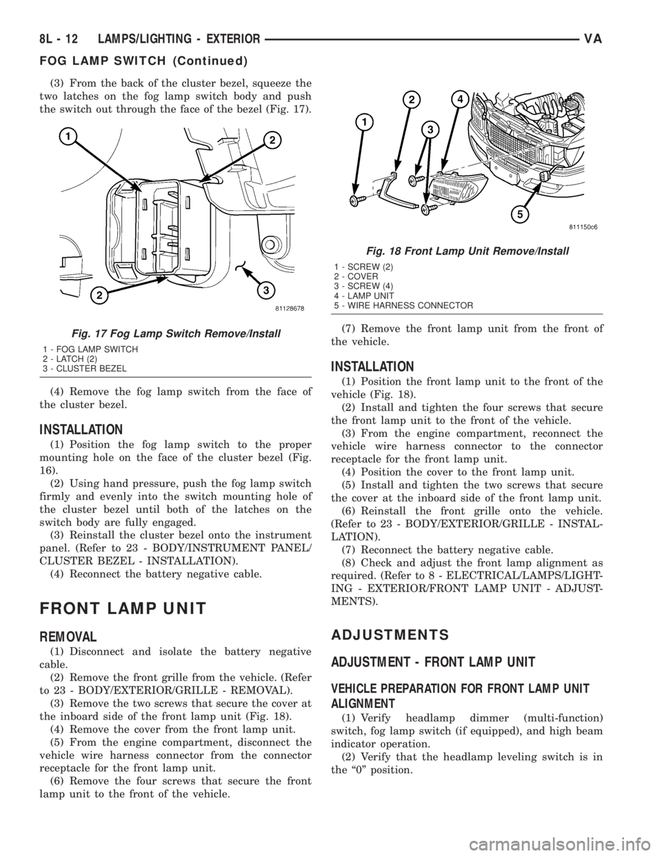
(3) From the back of the cluster bezel, squeeze the
two latches on the fog lamp switch body and push
the switch out through the face of the bezel (Fig. 17).
(4) Remove the fog lamp switch from the face of
the cluster bezel.
INSTALLATION
(1) Position the fog lamp switch to the proper
mounting hole on the face of the cluster bezel (Fig.
16).
(2) Using hand pressure, push the fog lamp switch
firmly and evenly into the switch mounting hole of
the cluster bezel until both of the latches on the
switch body are fully engaged.
(3) Reinstall the cluster bezel onto the instrument
panel. (Refer to 23 - BODY/INSTRUMENT PANEL/
CLUSTER BEZEL - INSTALLATION).
(4) Reconnect the battery negative cable.
FRONT LAMP UNIT
REMOVAL
(1) Disconnect and isolate the battery negative
cable.
(2) Remove the front grille from the vehicle. (Refer
to 23 - BODY/EXTERIOR/GRILLE - REMOVAL).
(3) Remove the two screws that secure the cover at
the inboard side of the front lamp unit (Fig. 18).
(4) Remove the cover from the front lamp unit.
(5) From the engine compartment, disconnect the
vehicle wire harness connector from the connector
receptacle for the front lamp unit.
(6) Remove the four screws that secure the front
lamp unit to the front of the vehicle.(7) Remove the front lamp unit from the front of
the vehicle.
INSTALLATION
(1) Position the front lamp unit to the front of the
vehicle (Fig. 18).
(2) Install and tighten the four screws that secure
the front lamp unit to the front of the vehicle.
(3) From the engine compartment, reconnect the
vehicle wire harness connector to the connector
receptacle for the front lamp unit.
(4) Position the cover to the front lamp unit.
(5) Install and tighten the two screws that secure
the cover at the inboard side of the front lamp unit.
(6) Reinstall the front grille onto the vehicle.
(Refer to 23 - BODY/EXTERIOR/GRILLE - INSTAL-
LATION).
(7) Reconnect the battery negative cable.
(8) Check and adjust the front lamp alignment as
required. (Refer to 8 - ELECTRICAL/LAMPS/LIGHT-
ING - EXTERIOR/FRONT LAMP UNIT - ADJUST-
MENTS).
ADJUSTMENTS
ADJUSTMENT - FRONT LAMP UNIT
VEHICLE PREPARATION FOR FRONT LAMP UNIT
ALIGNMENT
(1) Verify headlamp dimmer (multi-function)
switch, fog lamp switch (if equipped), and high beam
indicator operation.
(2) Verify that the headlamp leveling switch is in
the ª0º position.
Fig. 17 Fog Lamp Switch Remove/Install
1 - FOG LAMP SWITCH
2 - LATCH (2)
3 - CLUSTER BEZEL
Fig. 18 Front Lamp Unit Remove/Install
1 - SCREW (2)
2 - COVER
3 - SCREW (4)
4 - LAMP UNIT
5 - WIRE HARNESS CONNECTOR
8L - 12 LAMPS/LIGHTING - EXTERIORVA
FOG LAMP SWITCH (Continued)
Page 212 of 1232
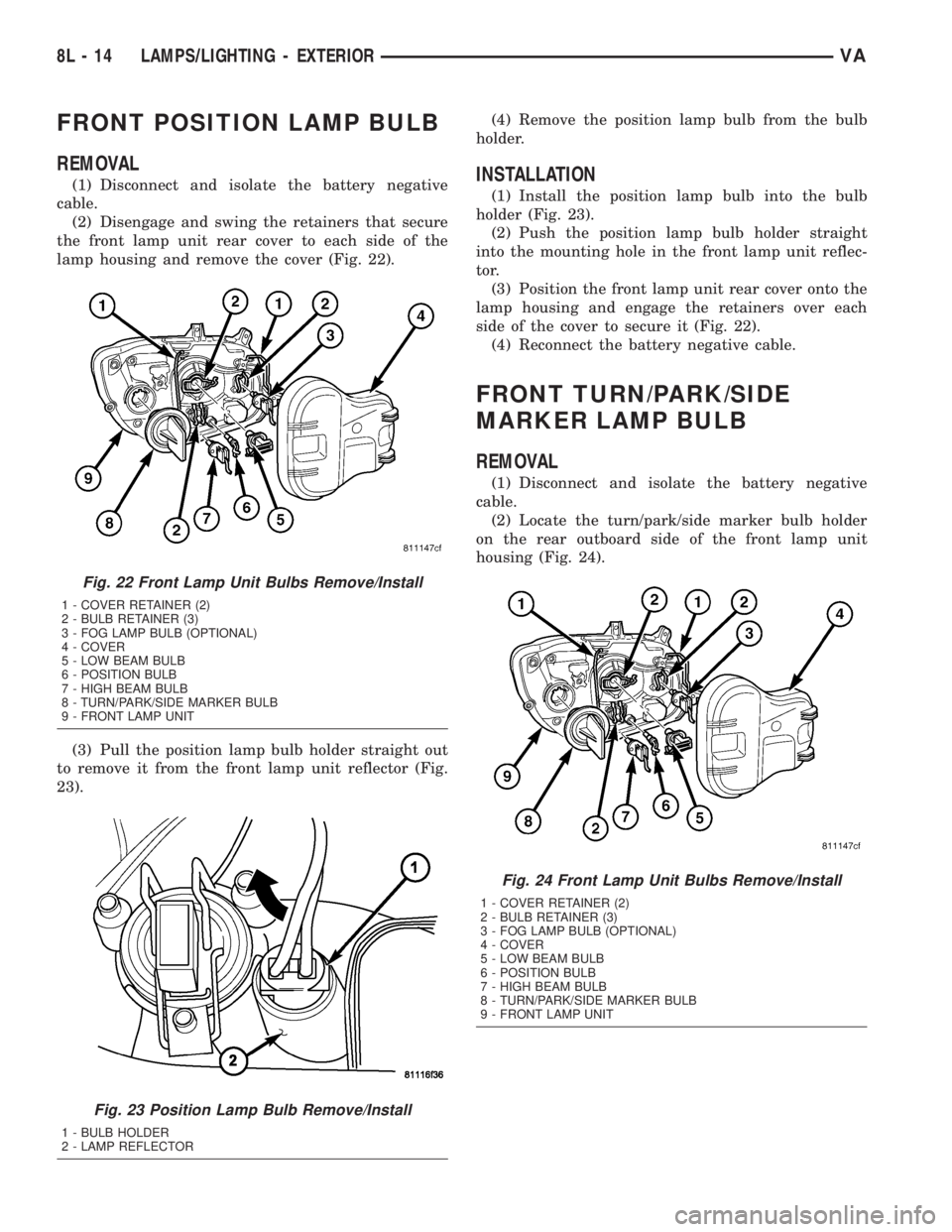
FRONT POSITION LAMP BULB
REMOVAL
(1) Disconnect and isolate the battery negative
cable.
(2) Disengage and swing the retainers that secure
the front lamp unit rear cover to each side of the
lamp housing and remove the cover (Fig. 22).
(3) Pull the position lamp bulb holder straight out
to remove it from the front lamp unit reflector (Fig.
23).(4) Remove the position lamp bulb from the bulb
holder.INSTALLATION
(1) Install the position lamp bulb into the bulb
holder (Fig. 23).
(2) Push the position lamp bulb holder straight
into the mounting hole in the front lamp unit reflec-
tor.
(3) Position the front lamp unit rear cover onto the
lamp housing and engage the retainers over each
side of the cover to secure it (Fig. 22).
(4) Reconnect the battery negative cable.
FRONT TURN/PARK/SIDE
MARKER LAMP BULB
REMOVAL
(1) Disconnect and isolate the battery negative
cable.
(2) Locate the turn/park/side marker bulb holder
on the rear outboard side of the front lamp unit
housing (Fig. 24).
Fig. 22 Front Lamp Unit Bulbs Remove/Install
1 - COVER RETAINER (2)
2 - BULB RETAINER (3)
3 - FOG LAMP BULB (OPTIONAL)
4 - COVER
5 - LOW BEAM BULB
6 - POSITION BULB
7 - HIGH BEAM BULB
8 - TURN/PARK/SIDE MARKER BULB
9 - FRONT LAMP UNIT
Fig. 23 Position Lamp Bulb Remove/Install
1 - BULB HOLDER
2 - LAMP REFLECTOR
Fig. 24 Front Lamp Unit Bulbs Remove/Install
1 - COVER RETAINER (2)
2 - BULB RETAINER (3)
3 - FOG LAMP BULB (OPTIONAL)
4 - COVER
5 - LOW BEAM BULB
6 - POSITION BULB
7 - HIGH BEAM BULB
8 - TURN/PARK/SIDE MARKER BULB
9 - FRONT LAMP UNIT
8L - 14 LAMPS/LIGHTING - EXTERIORVA