Page 372 of 969

8. INSTALL REAR AXLE HUB & BEARING ASSY")
C83035
C83015
C83016
C83008
- DRIVE SHAFT / PROPELLER SHAFTREAR AXLE HUB & BEARING ASSY LH
30-27
2430 Author�: Date�:
2005 LEXUS ES330 REPAIR MANUAL (RM1124U)
8. INSTALL REAR AXLE HUB & BEARING ASSY LH
(a) Install the rear axle hub & bearing assy LH with the 4 bolts.
Torque: 80 NVm (816 kgfVcm, 59 ftVlbf)
9. INSTALL SKID CONTROL SENSOR WIRE
10. INSPECT BEARING BACKLASH
(a) Set a dial indicator near the center of the axle hub and
check the backlash in the bearing shaft direction.
Maximum: 0.05 mm (0.0020 in.)
If the backlash exceeds the maximum, replace the axle hub as-
sembly.
11. INSPECT AXLE HUB DEVIATION
(a) Using a dial indicator, check the deviation at the surface
of the axle hub outside the hub bolt.
Maximum: 0.07 mm (0.0028 in.)
If the backlash exceeds the maximum, replace the axle hub as-
sembly.
12. INSTALL REAR DISC
13. INSTALL REAR DISC BRAKE CALIPER ASSY LH
(a) Install the rear disc brake caliper assy LH with the 2 bolts.
Torque: 62 NVm (630 kgfVcm, 46 ftVlbf)
Page 373 of 969
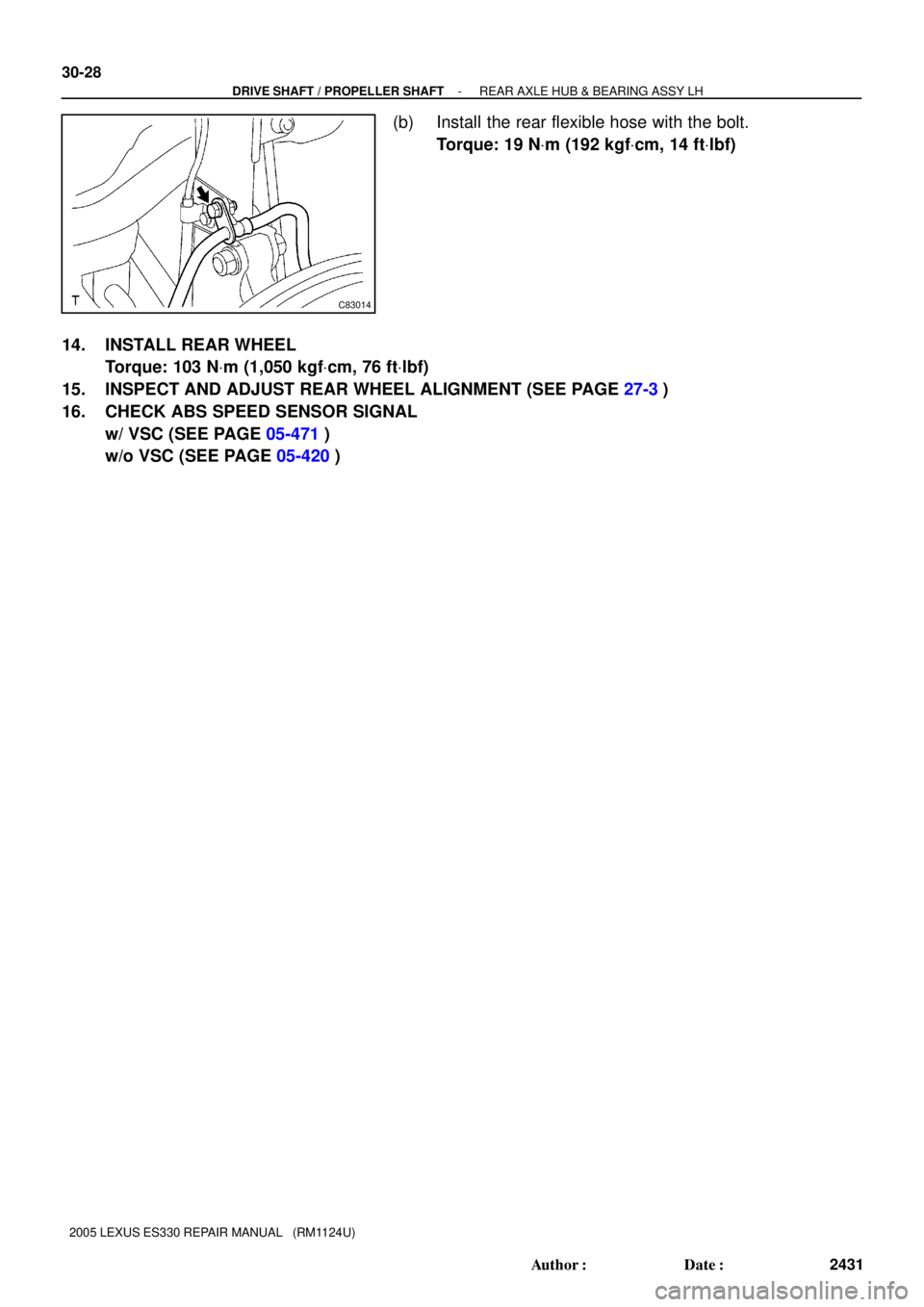
C83014
30-28
- DRIVE SHAFT / PROPELLER SHAFTREAR AXLE HUB & BEARING ASSY LH
2431 Author�: Date�:
2005 LEXUS ES330 REPAIR MANUAL (RM1124U)
(b) Install the rear flexible hose with the bolt.
Torque: 19 NVm (192 kgfVcm, 14 ftVlbf)
14. INSTALL REAR WHEEL
Torque: 103 NVm (1,050 kgfVcm, 76 ftVlbf)
15. INSPECT AND ADJUST REAR WHEEL ALIGNMENT (SEE PAGE 27-3)
16. CHECK ABS SPEED SENSOR SIGNAL
w/ VSC (SEE PAGE 05-471)
w/o VSC (SEE PAGE 05-420)
Page 374 of 969

REAR AXLE CARRIER SUB-ASSY LH
REPLACEME")
3006J-06
C83017
C83018
C83019
- DRIVE SHAFT / PROPELLER SHAFTREAR AXLE CARRIER SUB-ASSY LH
30-29
2432 Author�: Date�:
2005 LEXUS ES330 REPAIR MANUAL (RM1124U)
REAR AXLE CARRIER SUB-ASSY LH
REPLACEMENT
HINT:
�COMPONENTS: See page 30-4
�Replace the RH side by the same procedures with the LH side.
1. REMOVE REAR WHEEL
2. REMOVE STRUT ROD ASSY REAR (SEE PAGE 27-18)
3. DISCONNECT REAR DISC BRAKE CALIPER ASSY LH (SEE PAGE 30-26)
4. REMOVE REAR DISC
5. DISCONNECT SKID CONTROL SENSOR WIRE
6. REMOVE REAR AXLE HUB & BEARING ASSY LH (SEE PAGE 30-26)
7. SEPARATE REAR SUSPENSION ARM ASSY NO.2 LH
(a) Remove the bolt, nut and rear suspension arm assy No.2
LH from the rear axle carrier sub-assy LH.
HINT:
While fixing the nut, turn and remove the bolt.
8. SEPARATE REAR SUSPENSION ARM ASSY NO.1 LH
(a) Remove the bolt, nut and rear suspension arm assy No.1
LH from the rear axle carrier sub-assy LH.
HINT:
While fixing the nut, turn and remove the bolt.
9. REMOVE REAR AXLE CARRIER SUB-ASSY LH
(a) Remove the 2 bolts, nuts and rear axle carrier sub-assy
LH from the shock absorber assy rear LH.
NOTICE:
When removing bolt, stop the bolt from rotating and loosen
the nut.
Page 375 of 969

10. INSTALL REAR AXLE CARRIER SUB-ASSY LH
(a) In")
C83019
C83018
C83017
30-30
- DRIVE SHAFT / PROPELLER SHAFTREAR AXLE CARRIER SUB-ASSY LH
2433 Author�: Date�:
2005 LEXUS ES330 REPAIR MANUAL (RM1124U)
10. INSTALL REAR AXLE CARRIER SUB-ASSY LH
(a) Install the rear axle carrier sub-assy LH with the 2 bolts
and nuts.
Torque: 255 NVm (2,600 kgfVcm, 188 ftVlbf)
NOTICE:
When installing bolt, stop the bolt from rotating and torque
the nut.
HINT:
Insert the bolt from the rear side of the vehicle and install the
nut.
11. TEMPORARILY TIGHTEN REAR SUSPENSION ARM
ASSY NO.1 LH
(a) Install the rear suspension arm assy No.1 LH to the rear
axle carrier sub-assy LH with the bolt and nut, temporarily
tighten the bolt.
HINT:
Insert the bolt from the front side of the vehicle and while fixing
the nut, turn and install the bolt.
12. TEMPORARILY TIGHTEN REAR SUSPENSION ARM
ASSY NO.2 LH
(a) Install the rear suspension arm No.2 to the rear axle carri-
er sub-assy LH with the bolt and nut, temporarily tighten
the bolt.
HINT:
Insert the bolt from the rear side of the vehicle and while fixing
the nut, turn and install the bolt.
13. INSTALL REAR AXLE HUB & BEARING ASSY LH (SEE PAGE 30-26)
14. INSTALL SKID CONTROL SENSOR WIRE
15. INSTALL REAR DISC
16. INSTALL REAR DISC BRAKE CALIPER ASSY LH (SEE PAGE 30-26)
17. TEMPORARILY TIGHTEN STRUT ROD ASSY REAR (SEE PAGE 27-18)
18. STABILIZE SUSPENSION (SEE PAGE 27-18)
19. FULLY TIGHTEN REAR SUSPENSION ARM ASSY NO.1 LH (SEE PAGE 27-10)
20. FULLY TIGHTEN REAR SUSPENSION ARM ASSY NO.2 LH (SEE PAGE 27-14)
21. FULLY TIGHTEN STRUT ROD ASSY REAR (SEE PAGE 27-18)
22. INSTALL REAR WHEEL
Torque: 103 NVm (1,050 kgfVcm, 76 ftVlbf)
23. INSPECT AND ADJUST REAR WHEEL ALIGNMENT (SEE PAGE 27-3)
24. CHECK ABS SPEED SENSOR SIGNAL
w/ VSC (SEE PAGE 05-471)
w/o VSC (SEE PAGE 05-420)
Page 379 of 969

14-3
2095 Author�: Date�:
2005 LEXUS ES330 REPAIR MANUAL (RM1124U)
9. INSPECT COMPRESSION
(a) Warm up and stop the engine.
(b) Remove the")
P19471
Compression Gauge
- ENGINE MECHANICALENGINE (3MZ-FE)
14-3
2095 Author�: Date�:
2005 LEXUS ES330 REPAIR MANUAL (RM1124U)
9. INSPECT COMPRESSION
(a) Warm up and stop the engine.
(b) Remove the intake air surge tank (see page 11-13).
(c) Disconnect the injector connectors.
(d) Remove the ignition coils.
(e) Remove the spark plugs.
(f) Inspect the cylinder compression pressure.
(1) Insert a compression gauge into the spark plug
hole.
SST 09992-00500
(2) Fully open the throttle.
(3) While cranking the engine, measure the compres-
sion pressure.
Compression pressure:
1.5 MPa (15.3 kgf/cm
2, 218 psi)
Minimum pressure:
1.0 MPa (10.2 kgf/cm
2, 145 psi)
Difference between each cylinder:
100 kPa (1.0 kgf/cm
2, 15 psi)
NOTICE:
�Always use a fully-charged battery to obtain engine
speed of 250 rpm or more.
�Check the other cylinder's compression pressure in
the same way.
�This measurement must be done as quickly as pos-
sible.
(4) If the cylinder compression is low, pour a small
amount of engine oil into the cylinder through the
spark plug hole, then inspect again.
HINT:
�If adding oil increases the compression, the piston rings
and/or cylinder bore may be worn or damaged.
�If pressure stays low, the valve may be sticking or seated
improperly, or there may be leakage past the gasket.
10. INSPECT CO/HC
HINT:
The ECM properly controls the CO/HC concentration in the emission gas.
(a) Start the engine.
(b) Run the engine at 2,500 rpm for approximately 180 seconds.
(c) Insert the CO/HC meter testing probe at least 40 cm (1.3 ft) into the tailpipe during idling.
(d) Check the CO/HC concentration at idle and/or at 2,500 rpm.
HINT:
When doing the 2 mode (with the engine is at idle and at 2,500 rpm) tests, these measuring order are pre-
scribed by the applicable local regulations.
If the CO/HC concentration does not comply with the regulations, troubleshoot in the order given below.
(1) Check the heated oxygen sensor operation (see page 05-126).
Page 380 of 969
14-4
- ENGINE MECHANICALENGINE (3MZ-FE)
2096 Author�: Date�:
2005 LEXUS ES330 REPAIR MANUAL (RM1124U)
(2) See the table below for possible causes, then inspect the applicable causes and repair them if
necessary.
COHCProblemsCauses
NormalHighRough idle
5. Faulty ignitions:
�Incorrect timing
�Fouled, shorted or improperly gapped plugs
6. Incorrect valve clearance
7. Leaks in intake and exhaust valves
8. Leaks in cylinders
LowHighRough idle
(Fluctuating HC reading)
1. Vacuum leaks:
�PCV hoses
�Intake manifold
�Throttle body
�Brake booster line
2. Lean mixture causing misfire
HighHighRough idle
(Black smoke from exhaust)
1. Restricted air filter
2. Plugged PCV valve
3. Faulty SFI systems:
�Faulty pressure regulator
�Defective engine coolant temperature sensor
�Defective mass air flow meter
�Faulty ECM
�Faulty injectors
�Faulty throttle body
Page 394 of 969
A84926
N´m (kgf´cm, ft´lbf)
: Specified torque
49 (500, 36)
74 (755, 55)
75 (765, 55)
Steering Intermediate Shaft Assy
Front Suspension Arm
Sub-assy Lower No. 1 LH
Front Axle Hub LH Nut
Tie Rod Assy LH
Speed Sensor Front LH
� Cotter Pin
294 (2,998, 217)�
62 (633, 46)
Exhaust Pipe Assy Front
Exhaust Pipe No. 1
Support Bracket Front
8.0 (82, 71 in.Vlbf)
75 (765, 55)
� Exhaust Pipe Gasket
� Non-reusable part33 (337, 24)
35 (360, 26)
Front Stabilizer Link
Assy LH
35 (360, 26)
�
56 (571, 41)
� Exhaust Pipe
Gasket
33 (337, 24)
Exhaust Pipe No. 1
Support Bracket Rear
�
� Exhaust Pipe
Gasket
62 (633, 46)
14-18
- ENGINE MECHANICALPARTIAL ENGINE ASSY (3MZ-FE)
2110 Author�: Date�:
2005 LEXUS ES330 REPAIR MANUAL (RM1124U)
Page 398 of 969
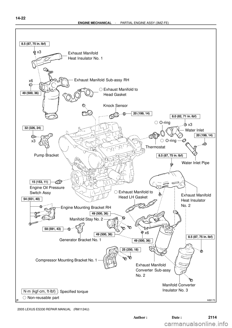
A86170
N´m (kgf´cm, ft´lbf)
: Specified torque
� Non-reusable part� O-ring
Manifold Converter
Insulator No. 3 Exhaust Manifold
Converter Sub-assy
No. 2 Manifold Stay No. 2
Compressor Mounting Bracket No. 1Generator Bracket No. 1Engine Mounting Bracket RH Engine Oil Pressure
Switch Assy� Exhaust Manifold to
Head LH Gasket
Exhaust Manifold
Heat Insulator
No. 2 Pump BracketKnock Sensor
Thermostat
Water Inlet Pipe � O-ringWater Inlet
� Exhaust Manifold to
Head Gasket
Exhaust Manifold
Heat Insulator No. 1
Exhaust Manifold Sub-assy RH
58 (591, 43)
54 (551, 40)
15 (153, 11)
32 (326, 24)
49 (500, 36)
8.5 (87, 75 in.Vlbf)
20 (199, 14)8.0 (82, 71 in.Vlbf)
20 (199, 14)
8.5 (87, 75 in.Vlbf)
8.5 (87, 75 in.Vlbf)49 (500, 36)
25 (250, 18)
49 (500, 36)
x3
x6
x3
x3
x6
49 (500, 36)
14-22
- ENGINE MECHANICALPARTIAL ENGINE ASSY (3MZ-FE)
2114 Author�: Date�:
2005 LEXUS ES330 REPAIR MANUAL (RM1124U)


: Specified torque
49 (500, 36)
74 (755, 55)
75 (765, 55)
Steering Intermediate Shaft Assy
Front Suspension Arm
Sub-assy Lower No. 1 LH
Front Axle Hub LH Nut
Tie Rod A")