Page 399 of 969
A78304
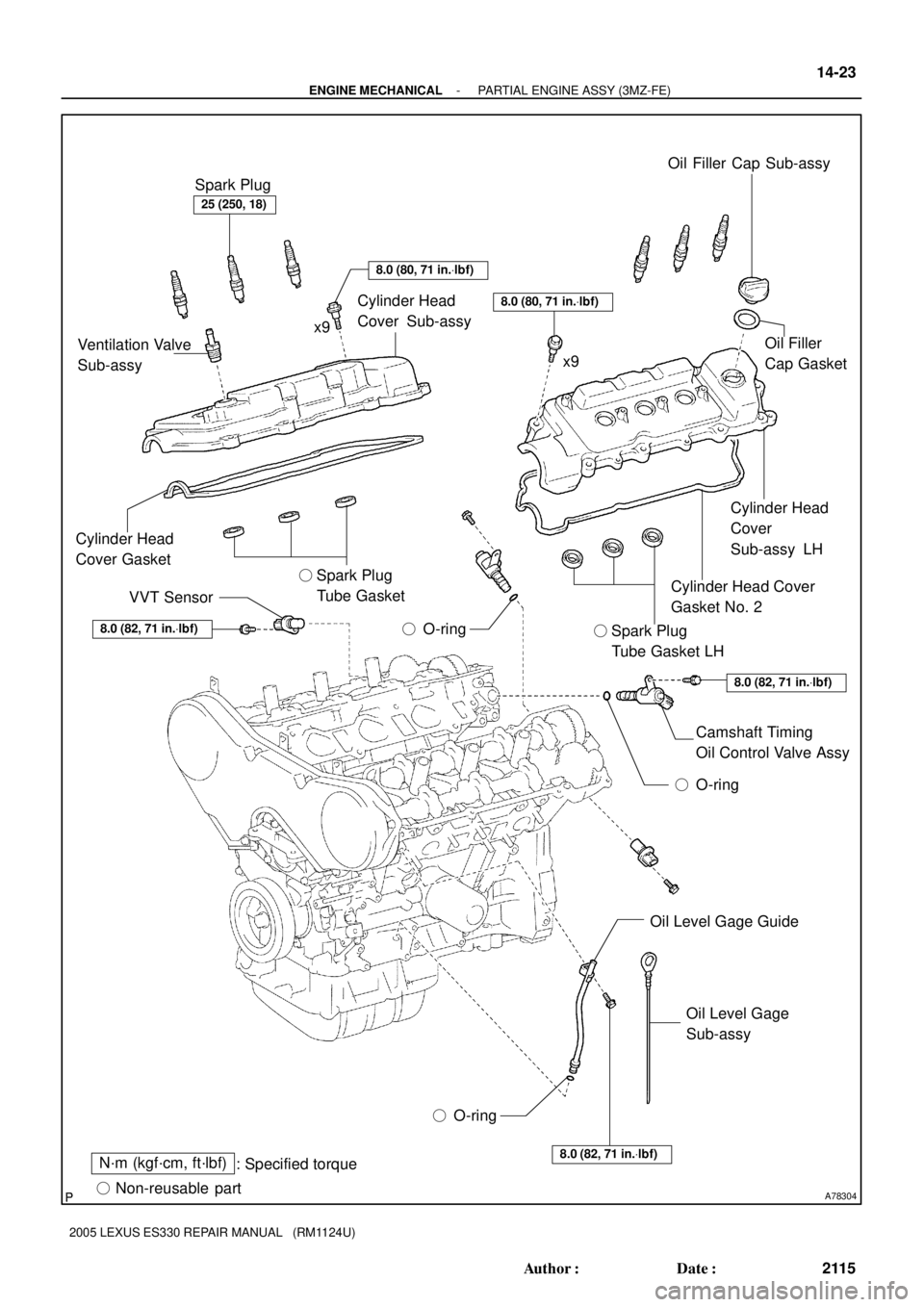
N´m (kgf´cm, ft´lbf)
: Specified torque
� Non-reusable part� O-ring� O-ring8.0 (82, 71 in.Vlbf)
8.0 (82, 71 in.Vlbf)
8.0 (82, 71 in.Vlbf)
8.0 (80, 71 in.Vlbf)
8.0 (80, 71 in.Vlbf)
25 (250, 18)
Spark Plug
Ventilation Valve
Sub-assyCylinder Head
Cover Sub-assy
Cylinder Head
Cover Gasket
VVT Sensor� Spark Plug
Tube Gasket
� O-ringOil Filler Cap Sub-assy
Oil Filler
Cap Gasket
Cylinder Head
Cover
Sub-assy LH
Cylinder Head Cover
Gasket No. 2
� Spark Plug
Tube Gasket LH
Camshaft Timing
Oil Control Valve Assy
Oil Level Gage Guide
Oil Level Gage
Sub-assy
x9
x9
- ENGINE MECHANICALPARTIAL ENGINE ASSY (3MZ-FE)
14-23
2115 Author�: Date�:
2005 LEXUS ES330 REPAIR MANUAL (RM1124U)
Page 401 of 969
A78306
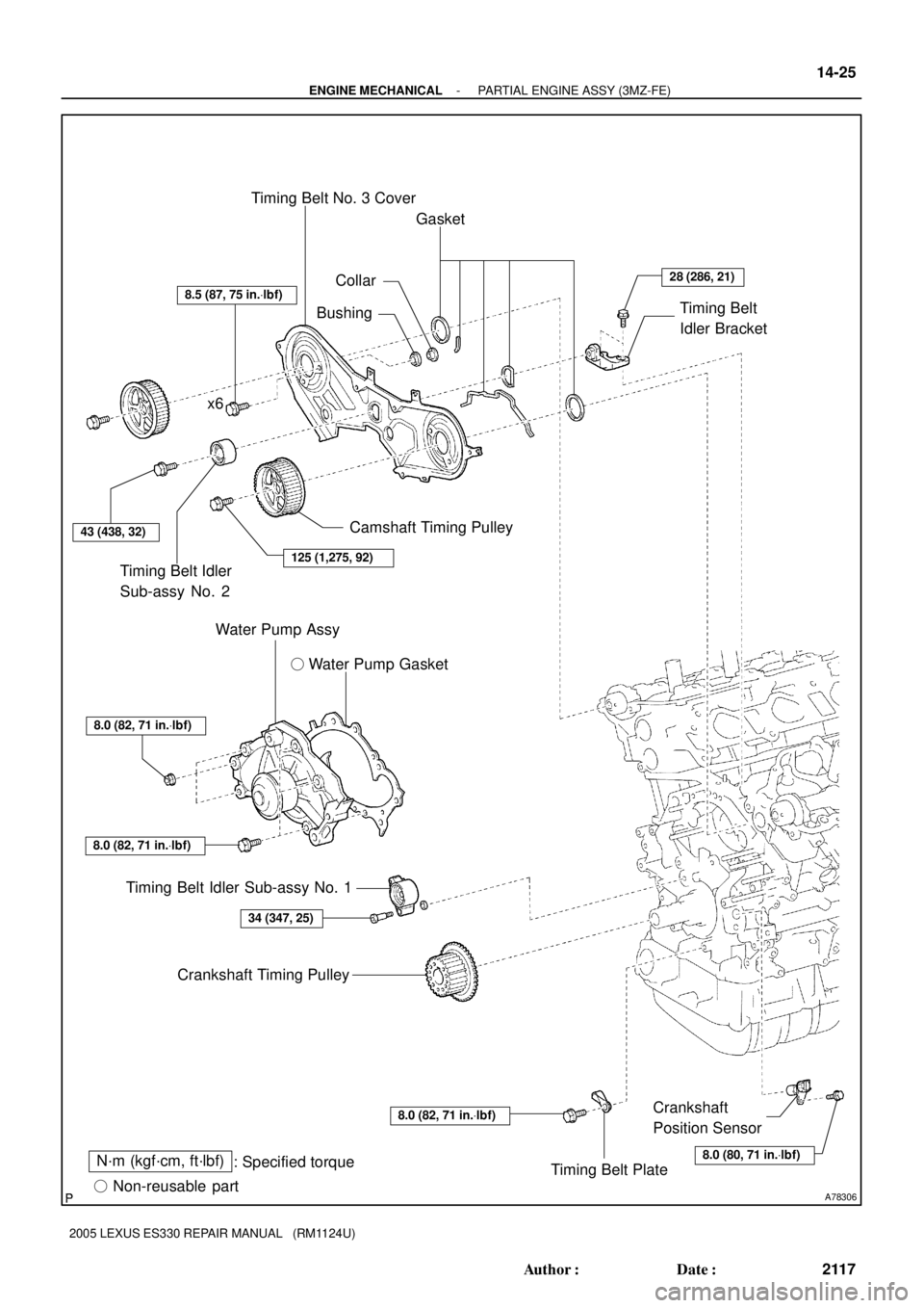
N´m (kgf´cm, ft´lbf)
: Specified torque
� Non-reusable part� Water Pump Gasket
28 (286, 21)
8.5 (87, 75 in.Vlbf)
125 (1,275, 92)
43 (438, 32)
8.0 (82, 71 in.Vlbf)
8.0 (82, 71 in.Vlbf)
34 (347, 25)
8.0 (80, 71 in.Vlbf)
8.0 (82, 71 in.Vlbf)
Timing Belt PlateCrankshaft
Position Sensor Crankshaft Timing Pulley Timing Belt Idler Sub-assy No. 1Water Pump Assy Timing Belt Idler
Sub-assy No. 2Camshaft Timing Pulley x6Timing Belt No. 3 Cover
CollarGasket
Timing Belt
Idler Bracket
Bushing
- ENGINE MECHANICALPARTIAL ENGINE ASSY (3MZ-FE)
14-25
2117 Author�: Date�:
2005 LEXUS ES330 REPAIR MANUAL (RM1124U)
Page 406 of 969

2122 Author�: Date�:
2005 LEXUS ES330 REPAIR MANUAL (RM1124U)
37. DISCONNECT STEERING GEAR OUTLET RETURN
TUBE
38. REMOVE GLOVE COM")
A60073
A59893
14-30
- ENGINE MECHANICALPARTIAL ENGINE ASSY (3MZ-FE)
2122 Author�: Date�:
2005 LEXUS ES330 REPAIR MANUAL (RM1124U)
37. DISCONNECT STEERING GEAR OUTLET RETURN
TUBE
38. REMOVE GLOVE COMPARTMENT DOOR ASSY (See page 10-22)
39. SEPARATE ENGINE WIRE
(a) Disconnect the engine wire harness from the ECM and
junction block.
(b) Disconnect the engine wire harness from the engine room
junction block.
(1) Remove the nut, then separate the engine wire har-
ness.
(2) Using a screwdriver, release the engine room junc-
tion block. Separate the engine wire harness by
pulling it upward.
(c) Remove the 2 nuts, then pull out the engine wire harness.
(d) Remove the body ground.
40. REMOVE EXHAUST PIPE NO.1 SUPPORT BRACKET FRONT (See page 15-2)
41. REMOVE EXHAUST PIPE NO.1 SUPPORT BRACKET REAR (See page 15-2)
42. REMOVE EXHAUST PIPE ASSY FRONT (See page 15-2)
43. DISCONNECT FRONT STABILIZER LINK ASSY LH (See page 30-8)
44. DISCONNECT FRONT STABILIZER LINK ASSY RH
HINT:
Perform the same procedure as above on the opposite side.
45. REMOVE FRONT AXLE HUB LH NUT (See page 30-8)
SST 09930-00010
46. REMOVE FRONT AXLE HUB RH NUT
SST 09930-00010
HINT:
Perform the same procedure as above on the opposite side.
47. SEPARATE SPEED SENSOR FRONT LH (See page 30-8)
48. SEPARATE SPEED SENSOR FRONT RH
HINT:
Perform the same procedure as above on the opposite side.
49. SEPARATE TIE ROD ASSY LH (See page 30-8)
SST 09628-6201 1
50. SEPARATE TIE ROD ASSY RH
SST 09628-6201 1
HINT:
Perform the same procedure as above on the opposite side.
Page 410 of 969

2126 Author�: Date�:
2005 LEXUS ES330 REPAIR MANUAL (RM1124U)
80. REMOVE MANIFOLD STAY NO.2
(a) Remove")
A86568
A05189
A80061
Oil Pressure
Switch 14-34
- ENGINE MECHANICALPARTIAL ENGINE ASSY (3MZ-FE)
2126 Author�: Date�:
2005 LEXUS ES330 REPAIR MANUAL (RM1124U)
80. REMOVE MANIFOLD STAY NO.2
(a) Remove the 2 bolts and manifold stay.
81. REMOVE ENGINE MOUNTING BRACKET RH (See page 17-9)
82. REMOVE PUMP BRACKET
(a) Remove the 3 bolts and pump bracket.
83. REMOVE GENERATOR BRACKET NO.1
84. REMOVE COMPRESSOR MOUNTING BRACKET NO.1 (See page 17-9)
85. REMOVE WATER INLET PIPE (See page 16-16)
86. REMOVE WATER INLET (See page 16-16)
87. REMOVE THERMOSTAT
88. REMOVE ENGINE OIL PRESSURE SWITCH ASSY
(a) Using a deep socket wrench 24 mm, remove the oil pres-
sure switch.
89. REMOVE KNOCK SENSOR (See page 10-16)
90. REPLACE PARTIAL ENGINE ASSY
91. INSTALL KNOCK SENSOR (See page 10-16)
92. INSTALL ENGINE OIL PRESSURE SWITCH ASSY
(a) Apply adhesive to 2 or 3 threads of the oil pressure switch.
Adhesive:
Part No. 08833-00080 THREE BOND 1344,
LOCTITE 242 or equivalent
(b) Using a deep socket wrench 24 mm, install the oil pressure switch.
Torque: 15 NVm (153 kgfVcm, 11 ftVlbf)
Page 413 of 969

14-37
2129 Author�: Date�:
2005 LEXUS ES330 REPAIR MANUAL (RM1124U)
122. INSTALL ENGINE ASSEMBLY WITH TRANS")
A59877
BNut
A
BNut
A
A59878
Nut
D
CNut
D
C
- ENGINE MECHANICALPARTIAL ENGINE ASSY (3MZ-FE)
14-37
2129 Author�: Date�:
2005 LEXUS ES330 REPAIR MANUAL (RM1124U)
122. INSTALL ENGINE ASSEMBLY WITH TRANSAXLE
(a) Set the engine assembly with the transaxle on the engine
lifter.
(b) Install the engine assembly to the vehicle.
(c) Install the frame side rail plate RH and LH with the 4 bolts
and 2 nuts.
Torque:
85 NVm (867 kgfVcm, 63 ftVlbf) for bolt A
32 NVm (326 kgfVcm, 24 ftVlbf) for bolt B and nut
(d) Install the front suspension member brace rear RH and
LH with the 4 bolts and 2 nuts.
Torque:
85 NVm (867 kgfVcm, 63 ftVlbf) for bolt C
32 NVm (326 kgfVcm, 24 ftVlbf) for bolt D and nut
123. CONNECT STEERING INTERMEDIATE SHAFT ASSY (See page 51-21)
124. INSTALL FRONT AXLE ASSY LH (See page 30-8)
125. INSTALL FRONT AXLE ASSY RH
HINT:
Perform the same procedure as above on the opposite side.
126. INSTALL FRONT SUSPENSION ARM SUB-ASSY LOWER NO.1 LH (See page 30-8)
127. INSTALL FRONT SUSPENSION ARM SUB-ASSY LOWER NO.1 RH
HINT:
Perform the same procedure as above on the opposite side.
128. INSTALL TIE ROD ASSY LH (See page 30-8)
129. INSTALL TIE ROD ASSY RH
HINT:
Perform the same procedure as above on the opposite side.
130. INSTALL SPEED SENSOR FRONT LH (See page 30-8)
131. INSTALL SPEED SENSOR FRONT RH
HINT:
Perform the same procedure as above on the opposite side.
132. INSTALL FRONT AXLE HUB LH NUT (See page 30-8)
133. INSTALL FRONT AXLE HUB RH NUT
HINT:
Perform the same procedure as above on the opposite side.
134. INSTALL FRONT STABILIZER LINK ASSY LH (See page 30-8)
135. INSTALL FRONT STABILIZER LINK ASSY RH
HINT:
Perform the same procedure as above on the opposite side.
136. INSTALL EXHAUST PIPE ASSY FRONT (See page 15-2)
137. INSTALL EXHAUST PIPE NO.1 SUPPORT BRACKET REAR (See page 15-2)
138. INSTALL EXHAUST PIPE NO.1 SUPPORT BRACKET FRONT (See page 15-2)
139. CONNECT FUEL PIPE SUB-ASSY NO.1 (See page 11-1)
Page 415 of 969
- ENGINE MECHANICALPARTIAL ENGINE ASSY (3MZ-FE)
14-39
2131 Author�: Date�:
2005 LEXUS ES330 REPAIR MANUAL (RM1124U)
157. ADD AUTOMATIC TRANSAXLE FLUID
158. ADD ENGINE OIL (See page 17-20)
159. ADD COOLANT (See page 16-9)
160. ADD POWER STEERING FLUID
161. BLEED POWER STEERING FLUID
162. INSPECT AUTOMATIC TRANSAXLE FLUID (See page 40-1)
163. CHECK FOR ENGINE OIL LEAKS
164. CHECK FOR ENGINE COOLANT LEAKS (See page 16-1)
165. CHECK POWER STEERING FLUID LEAKAGE
166. INSPECT FOR FUEL LEAKS
167. CHECK FOR EXHAUST GAS LEAKS
168. INSPECT AND ADJUST FRONT WHEEL ALIGNMENT (See page 26-5)
169. INSPECT STEERING WHEEL CENTER POINT
170. INSPECT IGNITION TIMING (See page 14-1)
SST 09843-18040
171. INSPECT ENGINE IDLE SPEED (See page 14-1)
172. INSPECT CO/HC (See page 14-1)
173. CHECK ABS SPEED SENSOR SIGNAL (See page 05-420, 05-471)
174. SYSTEM INITIALIZATION (See page 19-15)
Page 416 of 969

2132 Author�: Date�:
2005 LEXUS ES330 REPAIR MANUAL (RM1124U)
OVERHAUL
1. REMOVE SPARK PLUG
2. REMOVE OIL FILLER")
141CR-02
A78700
SST
A78701
SST 14-40
- ENGINE MECHANICALPARTIAL ENGINE ASSY (3MZ-FE)
2132 Author�: Date�:
2005 LEXUS ES330 REPAIR MANUAL (RM1124U)
OVERHAUL
1. REMOVE SPARK PLUG
2. REMOVE OIL FILLER CAP SUB-ASSY
3. REMOVE OIL FILLER CAP GASKET
4. REMOVE CYLINDER HEAD COVER SUB-ASSY LH
5. REMOVE CYLINDER HEAD COVER GASKET NO.2
6. REMOVE CYLINDER HEAD COVER SUB-ASSY
7. REMOVE CYLINDER HEAD COVER GASKET
8. REMOVE VENTILATION VALVE SUB-ASSY
9. REMOVE CAMSHAFT TIMING OIL CONTROL VALVE ASSY
10. REMOVE VVT SENSOR
(a) Remove both the camshaft oil control valves.
(b) Remove the O-ring from each camshaft oil control valve.
11. REMOVE OIL LEVEL GAGE SUB-ASSY
12. REMOVE OIL LEVEL GAGE GUIDE
13. REMOVE CRANKSHAFT PULLEY
(a) Using SST, loosen the pulley bolt.
SST 09213-54015 (91651-60855), 09330-00021
(b) Using SST and the pulley bolt, remove the pulley.
SST 09950- 50013 (09951- 05010, 09952- 05010,
09953-05020, 09954-05031)
NOTICE:
Before using SST, apply lubricating oil to the threads and
tip of the center bolt 150.
14. REMOVE TIMING BELT NO.1 COVER
15. REMOVE TIMING BELT NO.2 COVER
16. REMOVE ENGINE MOUNTING BRACKET RH
17. REMOVE TIMING BELT GUIDE NO.2
Page 418 of 969

(6) (1)(4) (2)(3)
A78703
SST
A78704
SST
A78705
SST 14-42
- ENGINE MECHANICALPARTIAL ENGINE ASSY (3MZ-FE)
2134 Author�: Date�:
2005 LEXUS ES330 REPAIR MANUAL (RM1124U)
(e) Remove the timin")
A78702
(5)
(6) (1)(4) (2)(3)
A78703
SST
A78704
SST
A78705
SST 14-42
- ENGINE MECHANICALPARTIAL ENGINE ASSY (3MZ-FE)
2134 Author�: Date�:
2005 LEXUS ES330 REPAIR MANUAL (RM1124U)
(e) Remove the timing belt in this order.
1stNo. 1 idler pulley
2ndRH camshaft timing pulley
3rdNo. 2 idler pulley
4thLH camshaft timing pulley
5thWater pump pulley
6thCrankshaft timing pulley
19. REMOVE TIMING BELT IDLER SUB-ASSY NO.1
(a) Using a socket hexagon wrench 10, remove the pivot bolt, timing belt idler No. 1 and plate washer.
20. REMOVE TIMING BELT IDLER SUB-ASSY NO.2
21. REMOVE CRANKSHAFT POSITION SENSOR
22. REMOVE CAMSHAFT TIMING PULLEY
(a) Using SST, remove the bolt and RH timing pulley.
SST 09960-10010 (09962-01000, 09963-01000)
(b) Using SST, remove the bolt and LH timing pulley.
SST 09960-10010 (09962-01000, 09963-01000)
HINT:
Arrange the camshaft timing pulleys (RH and LH sides) so that
they can be returned to the original locations when reassem-
bling.
23. REMOVE TIMING BELT NO.3 COVER
24. REMOVE TIMING BELT IDLER BRACKET
25. REMOVE CRANKSHAFT TIMING PULLEY
(a) Remove the bolt and timing belt plate.
(b) Install the pulley bolt to the crankshaft.
(c) Using SST, remove the crankshaft timing pulley.
SST 09950- 50013 (09951- 05010, 09952- 05010,
09953-05020, 09954-05011)
NOTICE:
�Do not scratch the sensor part of the crankshaft tim-
ing pulley.
�Before using SST, apply lubricating oil to the threads
and tip of the center bolt 150.