Page 431 of 969
 AAB
B Region ºXº Region ºYº
- ENGINE MECHANICALPARTIAL ENGINE ASSY (3MZ-FE)
14-55
2147 Author�: Date�:
2005 LEXU")
A51990
AB
C
B
A
AA
A
A
A78726
Seal Packing
Seal Width
3 to 4 mm
(0.12 to 0.16 in.) AAB
B Region ºXº Region ºYº
- ENGINE MECHANICALPARTIAL ENGINE ASSY (3MZ-FE)
14-55
2147 Author�: Date�:
2005 LEXUS ES330 REPAIR MANUAL (RM1124U)
(e) Install the oil pump with the 9 bolts. Tighten the bolts uni-
formly in several steps.
Torque:
8.0 NVm (82 kgfVcm, 71 in.Vlbf) for bolt A
20 NVm (199 kgfVcm, 14 ftVlbf) for bolt B
43 NVm (439 kgfVcm, 32 ftVlbf) for bolt C
61. INSTALL CRANKSHAFT POSITION SENSOR
Torque: 8.0 NVm (80 kgfVcm, 71 in.Vlbf)
62. INSTALL OIL PAN BAFFLE PLATE
Torque: 8.0 NVm (82 kgfVcm, 71 in.Vlbf)
63. INSTALL OIL PAN SUB-ASSY
(a) Remove any old seal packing from the contact surface.
(b) Apply a continuous bead of seal packing (Diameter 3 to
4 mm (0.12 to 0.16 in.)) as shown in the illustration.
Seal packing: Part No. 08826-00080 or equivalent
NOTICE:
�Remove any oil from the contact surface.
�Apply seal packing to the outer side of the bolt holes
in the region ºXº.
�Apply seal packing to the inner side of the bolt holes
in the region ºYº.
�Install the oil pan within 3 minutes after applying seal
packing.
�Do not expose the seal packing to engine oil within 2
hours after installing.
(c) Install the oil pan with the 15 bolts and 2 nuts. Tighten the
bolts uniformly in several steps.
Torque:
8.0 NVm (82 kgfVcm, 71 in.Vlbf) for 10 mm head
20 NVm (199 kgfVcm, 14 ftVlbf) for 12 mm head
64. INSTALL OIL STRAINER SUB-ASSY
(a) Install a new gasket and the oil strainer with the bolt and 2 nuts.
Torque: 8.0 NVm (82 kgfVcm, 71 in.Vlbf)
65. INSTALL OIL PAN SUB-ASSY NO.2
(a) Remove any old seal packing from the contact surface.
Page 440 of 969

2156 Author�: Date�:
2005 LEXUS ES330 REPAIR MANUAL (RM1124U)
79. INSTALL NO")
A78744
Align
A05214
A78745
10
1
2
3
45
6
7
8
9
A78746
Inward
Sensor 14-64
- ENGINE MECHANICALPARTIAL ENGINE ASSY (3MZ-FE)
2156 Author�: Date�:
2005 LEXUS ES330 REPAIR MANUAL (RM1124U)
79. INSTALL NO.3 CAMSHAFT SUB-ASSY
NOTICE:
Since the thrust clearance of the camshaft is small, the
camshaft must be kept level while being installed. If the
camshaft is not kept level, the cylinder head or camshaft
may be damaged. To avoid this, the following steps must
be carried out.
(a) Apply new engine oil to the thrust portion and journal of
the camshaft.
(b) Align the timing marks (1 dot marks) of the camshaft drive
and driven gears.
(c) Place the camshaft on the cylinder head.
(d) Install the 5 bearing caps in their proper locations.
(e) Apply a light coat of engine oil to the threads of the bear-
ing cap bolts.
(f) Using several steps, tighten the 10 bearing cap bolts uni-
formly in the sequence shown in the illustration.
Torque: 16 NVm (163 kgfVcm, 12 ftVlbf)
(g) Remove the service bolt.
80. INSTALL CRANKSHAFT TIMING PULLEY
(a) Align the keyway of the timing pulley with the key located
on the crankshaft, then slide the timing pulley into place.
NOTICE:
Do not scratch the sensor area of the crankshaft timing
pulley.
(b) Install the timing belt plate with the bolt.
Torque: 8.0 NVm (82 kgfVcm, 71 in.Vlbf)
Page 446 of 969

2162 Author�: Date�:
2005 LEXUS ES330 REPAIR MANUAL (RM1124U)
92. INSTALL ENGINE MOUNTING BRACKET RH
Torque: 28 NVm (286 kgfVc")
A78753
SST
A52345
14-70
- ENGINE MECHANICALPARTIAL ENGINE ASSY (3MZ-FE)
2162 Author�: Date�:
2005 LEXUS ES330 REPAIR MANUAL (RM1124U)
92. INSTALL ENGINE MOUNTING BRACKET RH
Torque: 28 NVm (286 kgfVcm, 21 ftVlbf)
93. INSTALL TIMING BELT NO.2 COVER
(a) Visually check for cracks and breaks on the gasket of the timing belt cover.
If there is a trace of water intrusion when checking visually, replace the timing belt cover.
(b) Install the timing belt cover.
Torque: 8.5 NVm (87 kgfVcm, 75 in.Vlbf)
94. INSTALL TIMING BELT NO.1 COVER
(a) Visually check for cracks and breaks on the gasket of the timing belt cover.
If there is a trace of water intrusion when checking visually, replace the timing belt cover.
(b) Install the timing belt cover.
Torque: 8.5 NVm (87 kgfVcm, 75 in.Vlbf)
95. INSTALL CRANKSHAFT PULLEY
(a) Align the keyway of the pulley with the key located on the
crankshaft, then slide the pulley into place.
(b) Using SST, install the pulley bolt.
SST 09213-54015 (91651-60855), 09330-00021
Torque: 220 NVm (2,250 kgfVcm, 162 ftVlbf)
96. INSTALL VVT SENSOR
Torque: 8.0 NVm (82 kgfVcm, 71 in.Vlbf)
97. INSTALL CAMSHAFT TIMING OIL CONTROL VALVE ASSY
Torque: 8.0 NVm (82 kgfVcm, 71 in.Vlbf)
98. INSTALL ENGINE HANGER NO.2
Torque: 20 NVm (199 kgfVcm, 14 ftVlbf)
99. INSPECT VALVE CLEARANCE
(a) Turn the crankshaft pulley, then align the timing notch with
the timing mark º0º of the timing belt No. 1 cover.
(b) Check that the valve lifters on the intake side of the No.
1 cylinder are not pushed by the cam.
If the valve lifters are pushed, turn the crankshaft 1 revolution
(360�) and align the marks as above.
Page 490 of 969
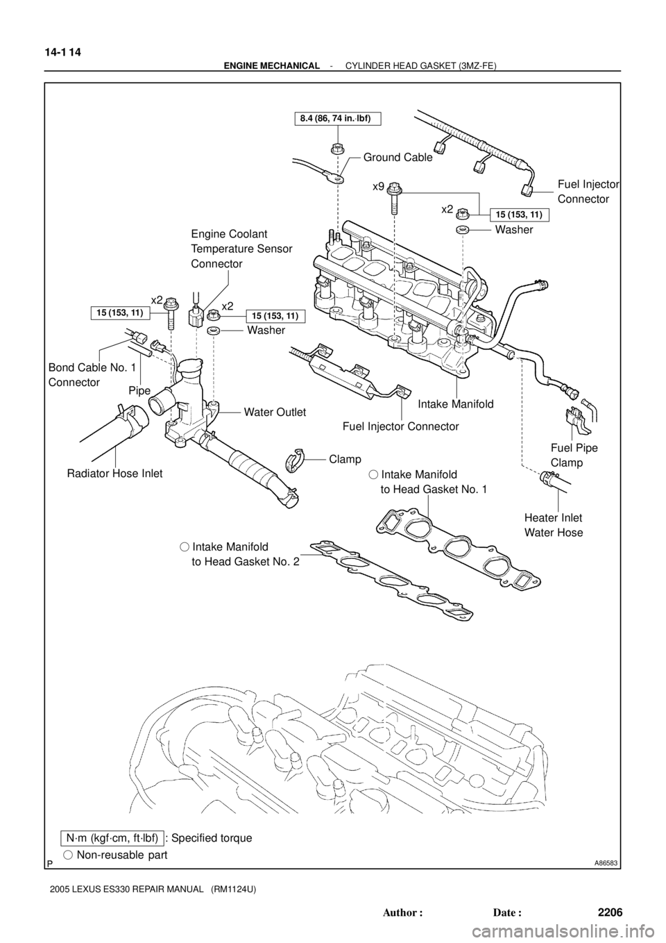
A86583� Non-reusable part
: Specified torqueN´m (kgf´cm, ft´lbf)� Intake Manifold
to Head Gasket No. 2� Intake Manifold
to Head Gasket No. 1
Radiator Hose InletWater Outlet
Heater Inlet
Water Hose Intake Manifold Ground Cable
Washer
8.4 (86, 74 in.Vlbf)
x2x9
x2
Washer
15 (153, 11)
15 (153, 11)
Fuel Pipe
Clamp
15 (153, 11)
Fuel Injector
Connector
Clamp
Fuel Injector Connector
x2
Engine Coolant
Temperature Sensor
Connector
Bond Cable No. 1
Connector
Pipe
14-1 14
- ENGINE MECHANICALCYLINDER HEAD GASKET (3MZ-FE)
2206 Author�: Date�:
2005 LEXUS ES330 REPAIR MANUAL (RM1124U)
Page 496 of 969

2212 Author�: Date�:
2005 LEXUS ES330 REPAIR MANUAL (RM1124U)
REPLACEMENT
1. DISCHARGE FUEL SYSTEM PRESSURE (See page 11-1)
2.")
141JH-01
A86571
14-120
- ENGINE MECHANICALCYLINDER HEAD GASKET (3MZ-FE)
2212 Author�: Date�:
2005 LEXUS ES330 REPAIR MANUAL (RM1124U)
REPLACEMENT
1. DISCHARGE FUEL SYSTEM PRESSURE (See page 11-1)
2. DISCONNECT BATTERY NEGATIVE TERMINAL
3. DRAIN ENGINE COOLANT (See page 16-9)
4. DRAIN ENGINE OIL (See page 17-20)
5. REMOVE FRONT WHEEL RH
6. REMOVE FRONT SUSPENSION UPPER BRACE CENTER (W/O TEMS) (See page 10-1 1)
7. REMOVE V-BANK COVER SUB-ASSY (See page 10-1 1)
8. REMOVE AIR CLEANER CAP SUB-ASSY (See page 10-1 1)
9. REMOVE EMISSION CONTROL VALVE SET (See page 11-13)
10. REMOVE INTAKE AIR SURGE TANK (See page 11-13)
11. REMOVE INTAKE MANIFOLD (See page 10-16)
12. REMOVE WATER OUTLET (See page 10-16)
13. REMOVE FRONT FENDER APRON SEAL RH
14. REMOVE V (COOLER COMPRESSOR TO CRANKSHAFT PULLEY) BELT NO.1
(See page 14-5)
15. REMOVE VANE PUMP V BELT (See page 14-5)
16. REMOVE ENGINE MOVING CONTROL ROD (See page 14-79)
17. REMOVE ENGINE MOUNTING STAY NO.2 RH (See page 14-79)
18. REMOVE GENERATOR BRACKET NO.2 (See page 14-79)
19. REMOVE CRANKSHAFT PULLEY (See page 14-79)
SST 09213-54015 (91651-60855), 09330-00021, 09950-50013 (09951-05010, 09952-05010,
09953-05020, 09954-05031)
20. REMOVE TIMING BELT NO.1 COVER
21. REMOVE TIMING BELT NO.2 COVER (See page 14-79)
22. REMOVE ENGINE MOUNTING BRACKET RH (See page 14-79)
23. REMOVE TIMING BELT GUIDE NO.2
24. REMOVE TIMING BELT (See page 14-79)
25. REMOVE TIMING BELT IDLER SUB-ASSY NO.2
26. REMOVE CAMSHAFT TIMING PULLEY (See page 14-93)
SST 09960-10010 (09962-01000, 09963-01000), 09249-63010
27. REMOVE TIMING BELT NO.3 COVER (See page 14-93)
28. SEPARATE VANE PUMP ASSY
29. REMOVE EXHAUST PIPE NO.1 SUPPORT BRACKET FRONT (See page 15-2)
30. REMOVE EXHAUST PIPE NO.1 SUPPORT BRACKET REAR (See page 15-2)
31. REMOVE EXHAUST PIPE ASSY FRONT (See page 15-2)
32. REMOVE EXHAUST MANIFOLD HEAT INSULATOR
NO.1
(a) Disconnect the air fuel ratio sensor connector.
(b) Remove the 3 bolts and exhaust manifold heat insulator.
Page 497 of 969

14-121
2213 Author�: Date�:
2005 LEXUS ES330 REPAIR MANUAL (RM1124U)
33. REMOVE EXHAU")
A86572
1
542
36
A78401
A78716
Front
A78717
Front
1
23
8
7
6
5
4
- ENGINE MECHANICALCYLINDER HEAD GASKET (3MZ-FE)
14-121
2213 Author�: Date�:
2005 LEXUS ES330 REPAIR MANUAL (RM1124U)
33. REMOVE EXHAUST MANIFOLD SUB-ASSY RH
(a) Using several steps, loosen and remove the 6 nuts in the
sequence shown in the illustration.
(b) Remove the exhaust manifold RH and gasket from the
cylinder head RH.
34. REMOVE IGNITION COIL ASSY
35. REMOVE CYLINDER HEAD COVER SUB-ASSY (See page 14-7)
36. REMOVE CAMSHAFT (See page 14-93)
37. REMOVE NO.2 CAMSHAFT (See page 14-93)
38. REMOVE CYLINDER HEAD SUB-ASSY
(a) Disconnect the VVT sensor connector.
(b) Disconnect the camshaft timing oil control valve connec-
tor.
(c) Remove the nut, then disconnect the engine wire harness
clamp.
(d) Using a socket hexagon wrench 8, remove the hexagon
bolt.
(e) Using several steps, loosen the 8 cylinder head bolts uni-
formly in the sequence shown in the illustration. Remove
the 8 cylinder head bolts and plate washers.
NOTICE:
�Be careful not to drop the washers into the cylinder
head.
�Head warpage or cracking could result from remov-
ing the bolts in an incorrect order.
39. REMOVE CYLINDER HEAD GASKET
Page 503 of 969
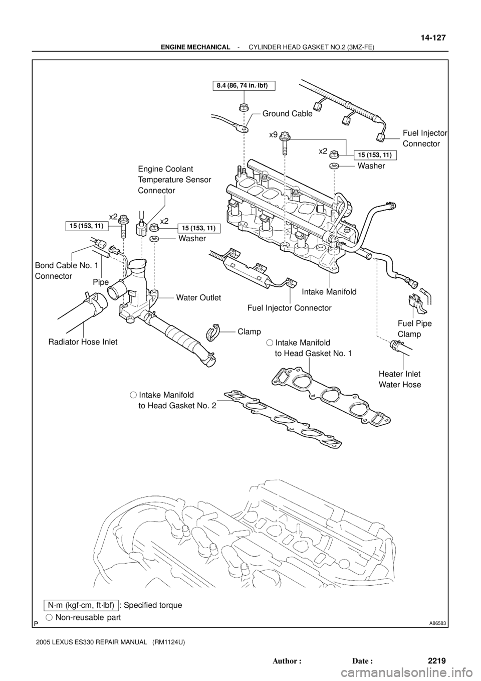
A86583� Non-reusable part
: Specified torqueN´m (kgf´cm, ft´lbf)� Intake Manifold
to Head Gasket No. 2� Intake Manifold
to Head Gasket No. 1
Radiator Hose InletWater Outlet
Heater Inlet
Water Hose Intake Manifold Ground Cable
Washer
8.4 (86, 74 in.Vlbf)
x2x9
x2
Washer
15 (153, 11)
15 (153, 11)
Fuel Pipe
Clamp
15 (153, 11)
Fuel Injector
Connector
Clamp
Fuel Injector Connector
x2
Engine Coolant
Temperature Sensor
Connector
Bond Cable No. 1
Connector
Pipe
- ENGINE MECHANICALCYLINDER HEAD GASKET NO.2 (3MZ-FE)
14-127
2219 Author�: Date�:
2005 LEXUS ES330 REPAIR MANUAL (RM1124U)
Page 510 of 969

2226 Author�: Date�:
2005 LEXUS ES330 REPAIR MANUAL (RM1124U)
34. REMOVE WAT")
A86575
A78718
Front
A78719
Front
1
23
8
7
6
5
4
A79822
Front 14-134
- ENGINE MECHANICALCYLINDER HEAD GASKET NO.2 (3MZ-FE)
2226 Author�: Date�:
2005 LEXUS ES330 REPAIR MANUAL (RM1124U)
34. REMOVE WATER INLET PIPE (See page 16-16)
35. REMOVE IGNITION COIL ASSY
36. REMOVE CYLINDER HEAD COVER SUB-ASSY LH (See page 14-7)
37. REMOVE NO.3 CAMSHAFT SUB-ASSY (See page 14-107)
38. REMOVE NO.4 CAMSHAFT SUB-ASSY (See page 14-107)
39. REMOVE CYLINDER HEAD LH
(a) Disconnect the VVT sensor connector.
(b) Disconnect the camshaft timing oil control valve connec-
tor.
(c) Disconnect the air fuel ratio sensor connector.
(d) Remove the bolt, then disconnect the ground cable.
(e) Remove the bolt and wire harness clamp bracket.
(f) Using a socket hexagon wrench 8, remove the hexagon
bolt.
(g) Using several steps, loosen the 8 cylinder head bolts uni-
formly in the sequence shown in the illustration. Remove
the 8 cylinder head bolts and plate washers.
NOTICE:
�Be careful not to drop the washers into the cylinder
head.
�Head warpage or cracking could result from remov-
ing the bolts in an incorrect order.
40. REMOVE CYLINDER HEAD GASKET NO.2
41. INSPECT CYLINDER HEAD SET BOLT (See page 14-120)
42. INSTALL CYLINDER HEAD GASKET NO.2
(a) Place a new cylinder head gasket on the cylinder block
with the L mark upward.
NOTICE:
�Remove any oil from the contact surface.
�Be careful of the installing orientation.
�Place the cylinder head on the gasket carefully in or-
der not to damage the gasket at the bottom part of the
head.