Page 461 of 969

14-85
2177 Author�: Date�:
2005 LEXUS ES330 REPAIR MANUAL (RM1124U)
18. INSTALL ENGINE MOUNTING BRACKET RH
(a) Install the engine mou")
P18814
A78760
SST
A52344
- ENGINE MECHANICALTIMING BELT (3MZ-FE)
14-85
2177 Author�: Date�:
2005 LEXUS ES330 REPAIR MANUAL (RM1124U)
18. INSTALL ENGINE MOUNTING BRACKET RH
(a) Install the engine mounting bracket RH with the 2 bolts
and nut.
Torque: 28 NVm (286 kgfVcm, 21 ftVlbf)
19. INSTALL TIMING BELT NO.2 COVER
(a) Visually check for cracks and breaks on the gasket of the timing belt cover.
If there is a trace of water intrusion when checking visually, replace the timing belt cover.
(b) Install the timing belt cover.
Torque: 8.5 NVm (87 kgfVcm, 75 in.Vlbf)
20. INSTALL TIMING BELT NO.1 COVER
(a) Visually check for cracks and breaks on the gasket of the timing belt cover.
If there is a trace of water intrusion when checking visually, replace the timing belt cover.
(b) Install the timing belt cover.
Torque: 8.5 NVm (87 kgfVcm, 75 in.Vlbf)
(c) Install the 2 engine wire protector clamps to the timing belt No. 3 cover.
21. INSTALL CRANKSHAFT PULLEY
(a) Align the keyway of the pulley with the key located on the
crankshaft, then slide the pulley into place.
(b) Using SST, install the pulley bolt.
SST 09213-54015 (91651-60855), 09330-00021
Torque: 220 NVm (2250 kgfVcm, 162 ftVlbf)
22. INSTALL GENERATOR BRACKET NO.2
Torque: 28 NVm (286 kgfVcm, 21 ftVlbf)
23. INSTALL ENGINE MOUNTING STAY NO.2 RH
(a) Install the engine mounting stay No. 2 and engine mount-
ing bracket No. 2 with the bolt.
Torque: 64 NVm (653 kgfVcm, 47 ftVlbf)
Page 462 of 969
A78546
A
B
A
A 14-86
- ENGINE MECHANICALTIMING BELT (3MZ-FE)
2178 Author�: Date�:
2005 LEXUS ES330 REPAIR MANUAL (RM1124U)
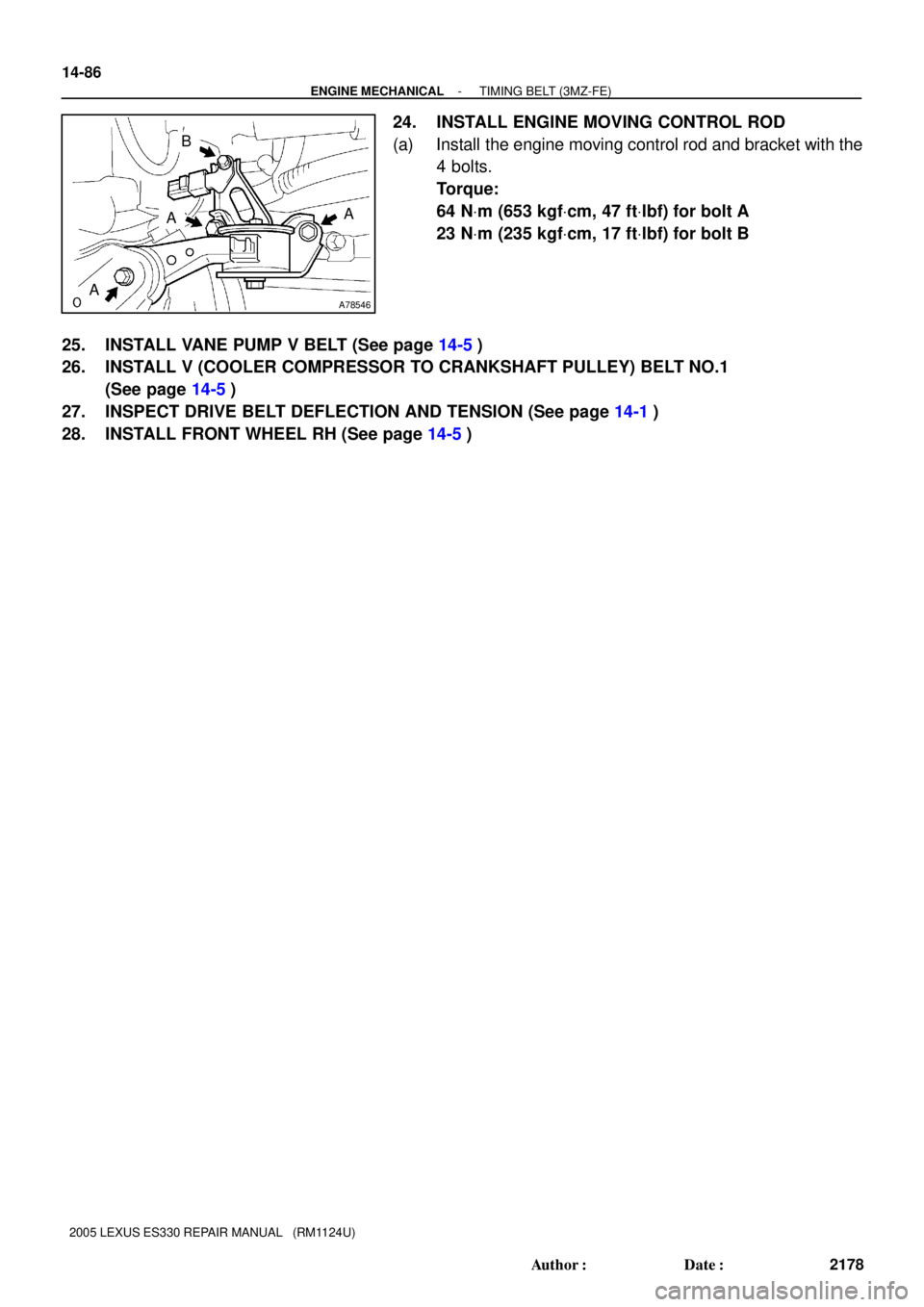
24. INSTALL ENGINE MOVING CONTROL ROD
(a) Install the engine moving control rod and bracket with the
4 bolts.
Torque:
64 NVm (653 kgfVcm, 47 ftVlbf) for bolt A
23 NVm (235 kgfVcm, 17 ftVlbf) for bolt B
25. INSTALL VANE PUMP V BELT (See page 14-5)
26. INSTALL V (COOLER COMPRESSOR TO CRANKSHAFT PULLEY) BELT NO.1
(See page 14-5)
27. INSPECT DRIVE BELT DEFLECTION AND TENSION (See page 14-1)
28. INSTALL FRONT WHEEL RH (See page 14-5)
Page 466 of 969
A78383
N´m (kgf´cm, ft´lbf)
: Specified torque
8.5 (87, 75 in.Vlbf)
220 (2,250, 162)
8.5 (87, 75 in.Vlbf)
28 (286, 21)
27 (280, 20)
Timing Belt Tensioner Assy Crankshaft PulleyTiming Belt No. 1 Cover
Timing Belt Guide No. 2
Engine Mounting Bracket RH Timing Belt No. 2 Cover
Timing Belt
Engine Wire
Protector
14-90
- ENGINE MECHANICALCAMSHAFT (RH BANK) (3MZ-FE)
2182 Author�: Date�:
2005 LEXUS ES330 REPAIR MANUAL (RM1124U)
Page 467 of 969
A78384N´m (kgf´cm, ft´lbf)
: Specified torque
8.5 (87, 75 in.Vlbf)
43 (438, 32)
Timing Belt Idler
Sub-assy No. 2x6Timing Belt No. 3 Cover
CollarGasket
Bushing
Camshaft Timing Pulley
125 (1,275, 92)
Engine Wire
- ENGINE MECHANICALCAMSHAFT (RH BANK) (3MZ-FE)
14-91
2183 Author�: Date�:
2005 LEXUS ES330 REPAIR MANUAL (RM1124U)
Page 469 of 969
 (3MZ-FE)
14-93
2185 Author�: Date�:
2005 LEXUS ES330 REPAIR MANUAL (RM1124U)
REPLACEMENT
1. DISCONNECT BATTERY NEGATIVE TE")
141JD-01
A78761
RH:
SST
A78762
SSTLH:
- ENGINE MECHANICALCAMSHAFT (RH BANK) (3MZ-FE)
14-93
2185 Author�: Date�:
2005 LEXUS ES330 REPAIR MANUAL (RM1124U)
REPLACEMENT
1. DISCONNECT BATTERY NEGATIVE TERMINAL
2. DRAIN ENGINE COOLANT (See page 16-9)
3. REMOVE FRONT WHEEL RH
4. REMOVE FRONT SUSPENSION UPPER BRACE CENTER (W/O TEMS) (See page 10-1 1)
5. REMOVE V-BANK COVER SUB-ASSY (See page 10-1 1)
6. REMOVE AIR CLEANER CAP SUB-ASSY (See page 10-1 1)
7. REMOVE EMISSION CONTROL VALVE SET (See page 11-13)
8. REMOVE INTAKE AIR SURGE TANK (See page 11-13)
9. REMOVE IGNITION COIL ASSY
10. REMOVE CYLINDER HEAD COVER SUB-ASSY (See page 14-7)
11. REMOVE FRONT FENDER APRON SEAL RH
12. REMOVE V (COOLER COMPRESSOR TO CRANKSHAFT PULLEY) BELT NO.1
(See page 14-5)
13. REMOVE VANE PUMP V BELT (See page 14-5)
14. REMOVE ENGINE MOVING CONTROL ROD (See page 14-79)
15. REMOVE ENGINE MOUNTING STAY NO.2 RH (See page 14-79)
16. REMOVE GENERATOR BRACKET NO.2 (See page 14-79)
17. REMOVE CRANKSHAFT PULLEY (See page 14-79)
SST 09213-54015 (91651-60855), 09330-00021, 09950-50013 (09951-05010, 09952-05010,
09953-05020, 09954-05031)
18. REMOVE TIMING BELT NO.1 COVER
19. REMOVE TIMING BELT NO.2 COVER (See page 14-79)
20. REMOVE ENGINE MOUNTING BRACKET RH (See page 14-79)
21. REMOVE TIMING BELT GUIDE NO.2
22. REMOVE TIMING BELT (See page 14-79)
23. REMOVE TIMING BELT IDLER SUB-ASSY NO.2
24. REMOVE CAMSHAFT TIMING PULLEY
(a) Using SST, remove the bolt and RH timing pulley.
SST 09960- 10010 (09962- 01000, 09963- 01000),
09249-63010
(b) Using SST, remove the bolt and LH timing pulley.
SST 09960-10010 (09962-01000, 09963-01000)
HINT:
Arrange the camshaft timing pulleys (RH and LH sides) so that
they can be returned to the original locations when reassem-
bling.
Page 470 of 969
 (3MZ-FE)
2186 Author�: Date�:
2005 LEXUS ES330 REPAIR M")
A05077
Clamp
Clamp
Clamp
A78706Align
A78707
Main GearSub Gear
Service Bolt
A78708
101
2
3
4
5
6
7
89 14-94
- ENGINE MECHANICALCAMSHAFT (RH BANK) (3MZ-FE)
2186 Author�: Date�:
2005 LEXUS ES330 REPAIR MANUAL (RM1124U)
25. REMOVE TIMING BELT NO.3 COVER
(a) Disconnect the 3 engine wire harness clamps from the
timing belt No. 3 cover.
(b) Remove the 6 bolts and timing belt cover.
26. REMOVE CAMSHAFT
NOTICE:
Since the thrust clearance of the camshaft is small, the
camshaft must be kept level while being removed. If the
camshaft is not kept level, the cylinder head or camshaft
may be damaged. To avoid this, the following steps must
be carried out.
(a) Align the timing marks (2 dot marks) of the camshaft drive
and driven gears by turning the camshaft with a wrench.
(b) Secure the exhaust camshaft sub gear to the main gear
with a service bolt.
Torque: 5.4 NVm (55 kgfVcm, 48 in.Vlbf)
Recommended service bolt
Thread diameter6 mm
Thread pitch1.0 mm
Bolt length16 to 20 mm
HINT:
When removing the camshaft, make certain that the torsional
spring force of the sub gear has been eliminated by installation
of the service bolt.
(c) Using several steps, loosen and remove the 10 bearing
cap bolts uniformly in the sequence shown in the illustra-
tion. Remove the 5 bearing caps and camshaft.
NOTICE:
�Do not pry out the camshaft.
�Be careful not to damage the contact surface of the
cylinder head that receives the shaft thrust.
Page 475 of 969
 (3MZ-FE)
14-99
2191 Author�: Date�:
2005 LEXUS ES330 REPAIR MANUAL (RM1124U)
33. INSTALL CAMSHAFT
NOTICE:
Since th")
A78739
Align
A05204
A78740
101
23
4
5
6
7
8
9
- ENGINE MECHANICALCAMSHAFT (RH BANK) (3MZ-FE)
14-99
2191 Author�: Date�:
2005 LEXUS ES330 REPAIR MANUAL (RM1124U)
33. INSTALL CAMSHAFT
NOTICE:
Since the thrust clearance of the camshaft is small, the
camshaft must be kept level while being installed. If the
camshaft is not kept level, the cylinder head or camshaft
may be damaged. To avoid this, the following steps must
be carried out.
(a) Apply new engine oil to the thrust portion and journal of
the camshaft.
(b) Align the timing marks (2 dot marks) of the camshaft drive
and driven gears.
(c) Place the camshaft on the cylinder head.
(d) Install the 5 bearing caps in their proper locations.
(e) Apply a light coat of engine oil to the threads of the bear-
ing cap bolts.
(f) Using several steps, tighten the 10 bearing cap bolts uni-
formly in the sequence shown in the illustration.
Torque: 16 NVm (163 kgfVcm, 12 ftVlbf)
(g) Remove the service bolt.
34. INSTALL TIMING BELT NO.3 COVER
(a) Visually check for cracks and breaks on the gasket of the
timing belt cover.
HINT:
If there is a trace of water intrusion when checking visually, re-
pair the gasket with seal packing when the crack length is within
2 to 3 cm (0.79 to 1.18 in.). Replace the gasket when the crack
length is 3 to 4 cm (1.18 to 1.57 in.) or longer.
Page 476 of 969
 (3MZ")
A78748
Seal Packing
Gasket
A78749
E
F
Joining
Line D
G
Gasket Joining Portion:
Seal Packing E
Joining
Line
A78750
FrontFront
Belt
GuideBelt
Guide
14-100
- ENGINE MECHANICALCAMSHAFT (RH BANK) (3MZ-FE)
2192 Author�: Date�:
2005 LEXUS ES330 REPAIR MANUAL (RM1124U)
(b) If the timing belt cover gasket is needed to repair, follow
the procedure below.
(1) Repair the cracks and breaks by applying seal
packing to the damaged area.
Seal packing: Part No. 08826-00080 or equivalent
NOTICE:
When applying the seal packing, apply it as wide and high
as the gasket.
(c) If the timing belt cover gasket is needed to replace, follow
the procedure below.
(1) Using a screwdriver and gasket scraper, remove
the remaining gasket.
NOTICE:
Be careful not to damage the timing belt cover.
(2) Remove the backing paper from a new gasket, then
affix the gasket along the groove of the timing belt
cover as shown in the illustration.
NOTICE:
�Affix the gasket in the center of the groove.
�At the corners, try to keep the gasket thickness uni-
form.
HINT:
GasketDEFG
Length335 mm
(13.19 in.)180 mm
(7.09 in.)133 mm
(5.24 in.)72 mm
(2.83 in.)
(3) If there is a gap between the ends of the gasket, ap-
ply seal packing to close the gap.
Seal packing: Part No. 08826-00080 or equivalent
NOTICE:
When applying the seal packing, apply it as wide and high
as the gasket.
(d) Install the timing belt cover with the 6 bolts.
Torque: 8.5 NVm (87 kgfVcm, 75 in.Vlbf)
35. INSTALL CAMSHAFT TIMING PULLEY
(a) Pay attention to the orientation of the belt guide. Install
the camshaft timing pulley with the belt guide properly ori-
ented, then tighten the bolt temporarily.
HINT:
�Align the belt guide of the RH timing pulley so it faces the
front of the engine as illustrated.
�Align the belt guide of the LH timing pulley so it faces the
rear of the engine as illustrated.

: Specified torque
8.5 (87, 75 in.Vlbf)
220 (2,250, 162)
8.5 (87, 75 in.Vlbf)
28 (286, 21)
27 (280, 20)
Timing Belt Tensioner Assy Crankshaft PulleyTiming Belt No. 1 Cov")

: Specified torque
8.5 (87, 75 in.Vlbf)
43 (438, 32)
Timing Belt Idler
Sub-assy No. 2x6Timing Belt No. 3 Cover
CollarGasket
Bushing
Camshaft Timing Pulley
125 (1,275, 92")