Page 689 of 969
A36784
A78725
Seal Packing
Seal Width
2 to 3 mm
(0.08 to 0.12 in.) A
A
BB
C
C
A36785
- LUBRICATIONOIL PUMP ASSY (3MZ-FE)
17-13
2318 Author�: Date�:
41. INSTALL OIL PUMP ASSY
(a) Remove any old seal packing material from the contact
surface.
(b) Apply a light coat of engine oil to a new O-ring, then place
it on the cylinder block.
(c) Apply a continuous bead of seal packing (Diameter 2 to
3 mm (0.08 to 0.12 in.)) as shown in the illustration.
Seal packing: Part No. 08826-00080 or equivalent
NOTICE:
�Remove any oil from contact surface.
�Apply seal packing to the inner side of the bolt holes.
�Install the oil pump within 3 minutes after applying
seal packing.
�Do not expose the seal packing to engine oil within 2
hours after installing.
(d) Align the key of the oil pump drive gear with the keyway
located on the crankshaft, then slide the oil pump into
place.
Page 708 of 969

26-5
2368 Author�: Date�:
2005 LEXUS ES330 REPAIR MANUAL (RM1124U)
FRO")
2605T-05
C91608
B Front:A
C91609
C Rear:
D
SA3213
A
DB
Front
C
F40165
- FRONT SUSPENSIONFRONT WHEEL ALIGNMENT (From July, 2003)
26-5
2368 Author�: Date�:
2005 LEXUS ES330 REPAIR MANUAL (RM1124U)
FRONT WHEEL ALIGNMENT (From July, 2003)
ADJUSTMENT
1. INSPECT TIRE (See page 26-5)
2. MEASURE VEHICLE HEIGHT
Vehicle height:
FrontA - B: 120 mm (4.72 in.)
RearD - C: 52 mm (2.05 in.)
Measuring points:
A: Ground clearance of front wheel center
B: Ground clearance of lower suspension arm No. 2 set bolt
center
C: Ground clearance of strut rod set bolt center
D: Ground clearance of rear wheel center
NOTICE:
Before inspecting the wheel alignment, adjust the vehicle
height to the specified value.
HINT:
Bounce the vehicle at the corners up and down to stabilize the
suspension and inspect the vehicle height.
3. INSPECT TOE-IN
Toe-in:
Toe-in
(total)A + B: 0° ± 12' (0° ± 0.2°)
C - D: 0 ± 2 mm (0 ± 0.08 in.)
If the toe-in is not within the specified value, adjust it at the rack
ends.
4. ADJUST TOE-IN
(a) Remove the rack boot set clips.
(b) Loosen the tie rod end lock nuts.
(c) Turn the right and left rack ends by an equal amount to
adjust the toe-in.
HINT:
Try to adjust the toe-in to the center of the specified value.
(d) Make sure that the lengths of the right and left rack ends
are the same.
(e) Torque the tie rod end lock nuts.
Torque: 74 N´m (755 kgf´cm, 55 ft´lbf)
(f) Place the boots on the seats and install the clips.
HINT:
Make sure that the boots are not twisted.
(g) Perform VSC system calibration. (See page 05-471)
Page 711 of 969
2606S-02
F40136
C91030
C93102
SST
26-8
- FRONT SUSPENSIONFRONT SHOCK ABSORBER WITH COIL SPRING
2371 Author�: Date�:
2005 LEXUS ES330 REPAIR MANUAL (RM1124U)
FRONT SHOCK ABSORBER WITH COIL SPRING
OVERHAUL
HINT:
COMPONENTS: See page 26-3.
1. REMOVE FRONT WHEEL
2. DISCONNECT FRONT STABILIZER LINK ASSY LH
(a) Remove the nut and disconnect the front stabilizer link
assy LH from the shock absorber assy front LH.
HINT:
If the ball joint turns together with the nut, use a hexagon (6 mm)
wrench to hold the stud.
3. REMOVE FRONT SHOCK ABSORBER CAP LH
(H-TEMS SUSPENSION)
(a) Disconnect the connector.
(b) Remove the 3 nuts, harness clamp and the front shock
absorber cap LH.
4. REMOVE FRONT SHOCK ABSORBER WITH COIL
SPRING
(a) w/ H-TEMS:
Using SST, loosen the lock nut.
SST 09817-33190
(b) w/o H-TEMS:
Loosen the lock nut.
NOTICE:
�Do not loosen except for the case with disassembling
the shock absorber assy front LH with coil spring.
�Do not remove the lock nut.
Page 714 of 969

(g) Install a new f")
F40162
F40169
OutsideOutside
F40140
C93871
C93102
SST
- FRONT SUSPENSIONFRONT SHOCK ABSORBER WITH COIL SPRING
26-1 1
2374 Author�: Date�:
2005 LEXUS ES330 REPAIR MANUAL (RM1124U)
(g) Install a new front suspension support bearing LH.
(h) Install the front suspension support sub-assy LH with the
mark facing to the outside of the vehicle.
(i) Temporarily tighten the new lock nut.
9. INSTALL FRONT SHOCK ABSORBER WITH COIL
SPRING
(a) Install the front shock absorber with coil spring as shown
in the illustration.
(b) Install the 3 nuts to the upper side of front shock absorber
with coil spring.
Torque: 80 NVm (816 kgfVcm, 59 ftVlbf)
NOTICE:
Be careful not to drop the 2 washers in the case that there
is front suspension upper brace center.
(c) Install the 2 bolts and 2 nuts to the lower side of front
shock absorber with coil spring.
Torque: 210 NVm (2,141 kgfVcm, 155 ftVlbf)
NOTICE:
When installing bolt, stop the bolt from rotating and torque
the nut.
(d) w/ H-TEMS:
Using SST, fully tighten the lock nut.
SST 09817-33190
Torque: 49 NVm (500 kgfVcm, 36 ftVlbf)
(e) w/o H-TEMS:
Fully tighten the lock nut.
Torque: 49 NVm (500 kgfVcm, 36 ftVlbf)
Page 725 of 969
 Visually check the belt for excessive wea")
51018-15
F40449
F40897
Normal
Abnormal
F40898
- POWER STEERINGPOWER STEERING SYSTEM
51-3
2578 Author�: Date�:
ON-VEHICLE INSPECTION
1. INSPECT DRIVE BELT
(a) Visually check the belt for excessive wear, frayed cords,
etc.
If any defect is found, replace the drive belt.
HINT:
Cracks on the rib side of a belt are considered acceptable. If the
missing chunks from the ribs are found on the belt, it should be
replaced.
2. BLEED POWER STEERING SYSTEM
(a) Check the fluid level.
(b) Jack up the front of the vehicle and support it with the
stands.
(c) Turn the steering wheel.
(1) With the engine stopped, turn the wheel slowly from
lock to lock several times.
(d) Lower the vehicle.
(e) Start the engine.
(1) Run the engine at idle for a few minutes.
(f) Turn the steering wheel.
(1) With the engine idling, turn the wheel to left or right
full lock position and keep it there for 2 - 3 seconds,
then turn the wheel to the opposite full lock position
and keep it there for 2 - 3 seconds.
(2) Repeat (1) several times.
(g) Stop the engine.
(h) Check for forming or emulsification.
Especially, if the system has to be bled twice because of foam-
ing or emulsification, check for fluid leaks in the system.
(i) Check the fluid level.
3. CHECK FLUID LEVEL
(a) Keep the vehicle level.
(b) With the engine stopped, check the fluid level in the oil
reservoir.
If necessary, add fluid.
Fluid: ATF DEXRON® II or III
HINT:
Check that the fluid level is within the HOT LEVEL range on the
reservoir cap. If the fluid is cold, check that it is within the COLD
LEVEL range.
Page 726 of 969

or less 51-4
- POWER STEERINGPOWER STEERING SYSTEM
2579 Author�: Date�:
(c) Start the engine and run it at idle.
(d) Turn the st")
F40897
NormalAbnormal
R11786Engine Idling Engine Stopped5 mm (0.20 in.)
or less 51-4
- POWER STEERINGPOWER STEERING SYSTEM
2579 Author�: Date�:
(c) Start the engine and run it at idle.
(d) Turn the steering wheel from lock to lock several times to
raise fluid temperature.
Fluid temperature: 75 - 80°C (167 - 176°F)
(e) Check for foaming or emulsification.
If foaming or emulsification is identified, bleed the power steer-
ing system.
(f) With the engine idling, measure the fluid level in the oil
reservoir.
(g) Stop the engine.
(h) Wait a few minutes and remeasure the fluid level in the oil
reservoir.
Maximum fluid level rise: 5 mm (0.20 in.)
If a problem is found, bleed the power steering system.
(i) Check the fluid level.
4. CHECK STEERING FLUID PRESSURE
(a) Disconnect the pressure feed tube assy from the rack &
pinion power steering gear assy (See page 51-21).
(b) Connect SST, as shown in the illustration.
SST 09640-10010 (09641-01010, 09641-01020,
09641-01030)
NOTICE:
Check that the valve of the SST is in the open position.
(c) Bleed the power steering system.
(d) Start the engine and run it at idle.
(e) Turn the steering wheel from lock to lock several times to
raise fluid temperature.
Fluid temperature: 75 - 80 °C (167 - 176 °F)
Page 727 of 969

F41520
SST
OUT Attachment
Pressure Feed
Tube AssyAttachment
IN
Z15498
Oil
Reservoir
PS Vane
Pump PS Gear
SST Closed
Z15499
Oil
Reservoir
PS Vane
Pump PS Gear
SST Open
Z15500
Oil
Reservoir
PS Vane
Pump PS Gear
SST Open Lock Position
- POWER STEERINGPOWER STEERING SYSTEM
51-5
2580 Author�: Date�:
(f) With the engine idling, close the valve of the SST and ob-
serve the reading on the SST.
Fluid pressure:
7,800 - 8,300 kPa (80 - 85 kgf/cm
2, 1,138 - 1,209 psi)
NOTICE:
�Do not keep the valve closed for more than 10 se-
conds.
�Do not let the fluid temperature become too high.
(g) With the engine idling, open the valve fully.
(h) Measure the fluid pressure at engine speeds of 1,000 rpm
and 3,000 rpm.
Fluid pressure difference:
490 kPa (5 kgf/cm
2, 71 psi) or less
NOTICE:
Do not turn the steering wheel.
(i) With the engine idling and valve fully opened, turn the
steering wheel to full lock position.
Fluid pressure:
7,800 - 8,300 kPa (80 - 85 kgf/cm
2, 1,138 - 1,209 psi)
NOTICE:
�Do not maintain lock position for more than 10 se-
conds.
�Do not let the fluid temperature become too high.
Page 742 of 969
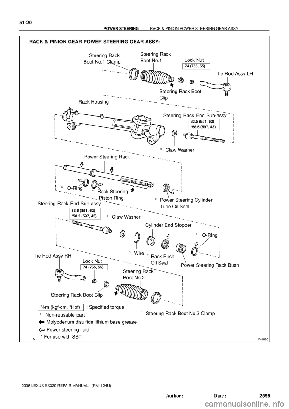
F41890
� Steering Rack
Boot No.1 ClampSteering Rack
Boot No.1
Lock Nut
Steering Rack Boot
Clip
Rack Housing
� Claw Washer
Steering Rack End Sub-assy
� Power Steering Cylinder
Tube Oil Seal
Power Steering Rack
� O-Ring� Rack Steering
Piston Ring
� O-Ring
Power Steering Rack Bush Cylinder End Stopper
� Wire
� Claw Washer
Steering Rack End Sub-assy
� Steering Rack Boot No.2 Clamp Steering Rack
Boot No.2
Steering Rack Boot ClipLock Nut
Tie Rod Assy RH
RACK & PINION GEAR POWER STEERING GEAR ASSY:
* For use with SST � Non-reusable part
NVm (kgfVcm, ftVlbf) : Specified torque
Molybdenum disulfide lithium base grease
Power steering fluid
Tie Rod Assy LH
Rack Bush
Oil Seal
�
74 (755, 55)
83.5 (851, 62)
*58.5 (597, 43)
83.5 (851, 62)
*58.5 (597, 43)
74 (755, 55)
51-20
- POWER STEERINGRACK & PINION POWER STEERING GEAR ASSY
2595 Author�: Date�:
2005 LEXUS ES330 REPAIR MANUAL (RM1124U)