Page 804 of 969
190SM-01
A81658
SST 1-A
SST 1-B
Turn
Hold
A81659
SST 2
Insert
SST 1
A81660
TurnSST1-A
A81661
SST 1-A
SST 1-B
Turn
Hold
- STARTING & CHARGINGGENERATOR ASSY (3MZ-FE)
19-23
2355 Author�: Date�:
2005 LEXUS ES330 REPAIR MANUAL (RM1124U)
OVERHAUL
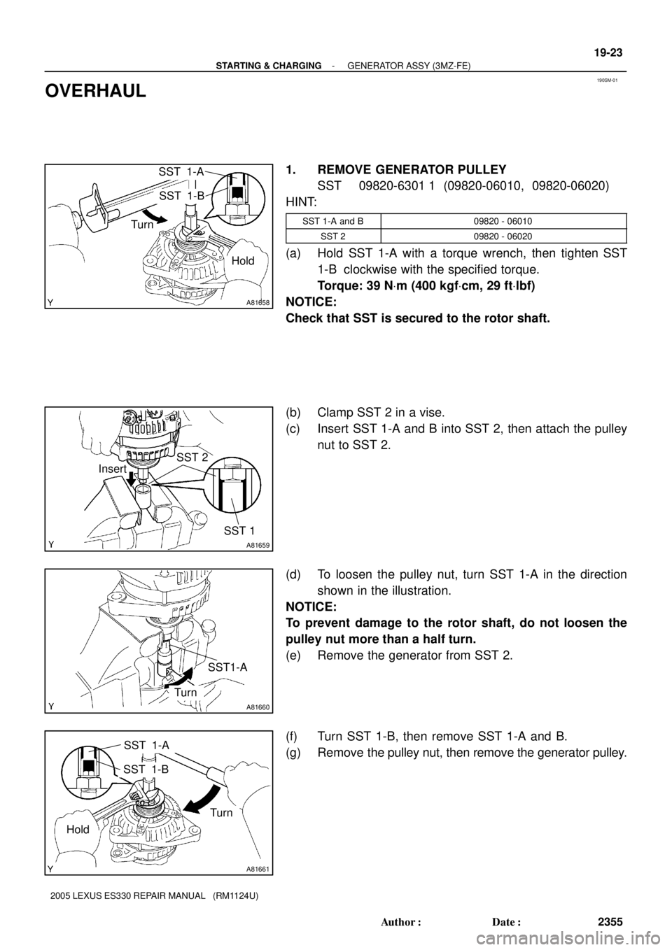
1. REMOVE GENERATOR PULLEY
SST 09820-6301 1 (09820-06010, 09820-06020)
HINT:
SST 1-A and B09820 - 06010
SST 209820 - 06020
(a) Hold SST 1-A with a torque wrench, then tighten SST
1-B clockwise with the specified torque.
Torque: 39 NVm (400 kgfVcm, 29 ftVlbf)
NOTICE:
Check that SST is secured to the rotor shaft.
(b) Clamp SST 2 in a vise.
(c) Insert SST 1-A and B into SST 2, then attach the pulley
nut to SST 2.
(d) To loosen the pulley nut, turn SST 1-A in the direction
shown in the illustration.
NOTICE:
To prevent damage to the rotor shaft, do not loosen the
pulley nut more than a half turn.
(e) Remove the generator from SST 2.
(f) Turn SST 1-B, then remove SST 1-A and B.
(g) Remove the pulley nut, then remove the generator pulley.
Page 808 of 969

A81146
A81164
A81658
SST 1-A
SST 1-B
Turn
Hold
- STARTING & CHARGINGGENERATOR ASSY (3MZ-FE)
19-27
2359 Author�: Date�:
2005 LEXUS ES330 REPAIR MANUAL (RM1124U)
(b) In")
A81672
Pin (f1.0 mm (0.039 in.)
A81146
A81164
A81658
SST 1-A
SST 1-B
Turn
Hold
- STARTING & CHARGINGGENERATOR ASSY (3MZ-FE)
19-27
2359 Author�: Date�:
2005 LEXUS ES330 REPAIR MANUAL (RM1124U)
(b) Install the generator brush holder with the 2 screws.
Torque: 1.8 NVm (18 kgfVcm, 16 in.Vlbf)
(c) Pull out the pin (f1.0 mm (0.039 in.)) from the generator
brush holder.
(d) Install the terminal insulator.
NOTICE:
Pay attention to the mounting orientation of the terminal in-
sulator.
(e) Install the generator rear end cover with the 3 nuts.
Torque: 4.6 NVm (47 kgfVcm, 41 in.Vlbf)
10. INSTALL GENERATOR PULLEY
SST 09820-6301 1 (09820-06010, 09820-06020)
HINT:
SST 1-A and B09820 - 06010
SST 209820 - 06020
(a) Install the generator pulley to the rotor shaft by tightening
the generator pulley nut by hand.
(b) Hold SST 1-A with a torque wrench, then tighten SST
1-B clockwise with the specified torque.
Torque: 39 NVm (400 kgfVcm, 29 ftVlbf)
NOTICE:
Check that SST is secured to the rotor shaft.
Page 814 of 969
R00429
Marked Line
F16018
- STEERING COLUMNSTEERING
50-5
2566 Author�: Date�:
2005 LEXUS ES330 REPAIR MANUAL (RM1124U)
(1) Draw a line on the RH and LH tie rod and rack ends
where it can easily be seen.
(2) Using a paper gauge, measure the distance from
RH and LH tie rod ends to the rack end screws.
HINT:
�Measure the RH side and LH side.
�Make a note of the measured values.
(3) Remove the RH and LH boot clips from the rack
boots.
(4) Loosen the RH and LH lock nuts.
(5) Turn the RH and LH rack end by the same amount
(but in different directions) according to the steering
angle.
1 turn 360 deg. of rack end (1.5 mm (0.059 in.) horizon-
tal movement) - 12 deg. of steering angle.
(6) Tighten the RH and LH lock nuts.
Torque: 74 NVm (755 kgfVcm, 55 ftVlbf)
NOTICE:
Make sure that the difference in length between RH and LH
tie rod ends and rack end screws are within 1.5 mm (0.059
in.).
(7) Install the RH and LH boot clips.
Page 816 of 969
C92308
NVm (kgfVcm, ftVlbf) : Specified torque
35 (360, 26)
��Non-reusable partUn-lock Waring
Switch AssyTransponder Key Amplifier
Ignition Switch Lock
Cylinder Assy
Steering Column Upper
w/ Switch Bracket Assy
Steering Column Assy
Ignition or Starter
Switch Assy
Steering Sliding
Yoke Sub-assySteering Column
Clamp Upper
� Tapered-Head Bolt
- STEERING COLUMNSTEERING COLUMN ASSY
50-7
2568 Author�: Date�:
2005 LEXUS ES330 REPAIR MANUAL (RM1124U)
Page 818 of 969
 Disconnect the 3 connectors.
(b) Disconnect the airbag connector.
(c) Rem")
C90687
C90688Matchmarks
- STEERING COLUMNSTEERING COLUMN ASSY
50-9
2570 Author�: Date�:
15. REMOVE TURN SIGNAL SWITCH ASSY
(a) Disconnect the 3 connectors.
(b) Disconnect the airbag connector.
(c) Remove the 3 screws and turn signal switch assy.
16. REMOVE INSTRUMENT PANEL FINISH PLATE(See page 71-1 1)
17. DISCONNECT FLOOR SHIFT PARKING LOCK CABLE
ASSY
(a) Place the ignition switch lock cylinder assy at the key ACC
position.
(b) Remove the cable cap claw from the key interlock and pull
out the floor shift parking lock cable assy.
18. DISCONNECT STEERING SLIDING YOKE SUB-ASSY
(a) Place the matchmarks on the steering sliding yoke sub-
assy and intermediate shaft sub-assy.
(b) Remove the bolt and disconnect the steering sliding yoke
sub-assy .
19. REMOVE STEERING COLUMN HOLE COVER SUB-ASSY NO.2
(a) Remove the hose clamp.
(b) Remove the steering column hole cover sub-assy No.2.
20. REMOVE STEERING COLUMN ASSY
(a) Disconnect the connectors and wire harness clamps.
(b) Disconnect the driver side junction block.
Page 820 of 969
 Using a centering punch, mark the cent")
C90693
Screw Extractor
C90695
C90696
- STEERING COLUMNSTEERING COLUMN ASSY
50-1 1
2572 Author�: Date�:
24. REMOVE STEERING COLUMN UPPER W/SWITCH
BRACKET ASSY
(a) Using a centering punch, mark the center of the 2 ta-
pered-head bolts.
(b) Using a 3 - 4 mm (0.12 - 0.16 in.) drill, drill in to the 2 bolts.
(c) Using a screw extractor, remove the 2 bolts and steering
column upper w/switch bracket assy.
25. REMOVE IGNITION SWITCH LOCK CYLINDER ASSY
(a) Place the ignition switch lock cylinder assy at the ACC
position.
(b) Push down the stop pin with a screwdriver, and pull out
the ignition switch lock cylinder assy.
26. REMOVE UN-LOCK WARNING SWITCH ASSY
(a) Disconnect the un-lock warning switch assy connector
from the ignition or starter switch assy.
(b) Remove the un-lock warning switch assy by pushing up
the center part and releasing the 2 screws.
27. REMOVE IGNITION OR STARTER SWITCH ASSY
(a) Remove the 2 screws and ignition or starter switch assy from the steering column upper w/switch
bracket assy.
28. INSTALL IGNITION OR STARTER SWITCH ASSY
(a) Install the ignition switch assy to the steering column upper w/switch bracket assy with the 2 screws.
29. INSTALL UN-LOCK WARNING SWITCH ASSY
(a) Install the un-lock warning switch assy.
(b) Connect the un-lock warning switch assy connector to the ignition or starter switch assy.
30. INSTALL IGNITION SWITCH LOCK CYLINDER ASSY
(a) Make sure the ignition switch lock cylinder assy at the ACC position.
(b) Install the ignition switch lock cylinder assy.
31. INSPECT STEERING LOCK OPERATION
(a) Check that the steering lock mechanism is activated when removing the key.
(b) Check that the steering lock mechanism is deactivated when inserting the key and turning it to ACC
position.
Page 822 of 969
 Install the steering column assy with the 2 nuts and bolt.
Torque: 21 NVm")
C90690
C90688
Matchmarks
- STEERING COLUMNSTEERING COLUMN ASSY
50-13
2574 Author�: Date�:
37. INSTALL STEERING COLUMN ASSY
(a) Install the steering column assy with the 2 nuts and bolt.
Torque: 21 NVm (214 kgfVcm, 15 ftVlbf)
(b) Connect the driver side junction block.
(c) Connect the connectors and wire harness clamps.
38. CONNECT STEERING SLIDING YOKE SUB-ASSY
(a) Align the matchmarks on the steering sliding yoke sub-
assy and steering intermediate shaft sub-assy.
(b) Connect the steering sliding yoke sub-assy with the bolt.
Torque: 35 NVm (360 kgfVcm, 26 ftVlbf)
39. CONNECT FLOOR SHIFT PARKING LOCK CABLE ASSY
(a) Place the ignition switch lock cylinder assy at the key ACC position.
(b) Install the floor shift parking lock cable assy.
40. INSPECT CHECK KEY INTERLOCK OPERATION(See page 40-31)
41. INSTALL INSTRUMENT PANEL FINISH PLATE(See page 71-1 1)
42. INSTALL TURN SIGNAL SWITCH ASSY
(a) Install the turn signal switch assy with the 3 screws.
(b) Connect the airbag connector.
(c) Connect the 3 connectors.
43. INSPECT SPIRAL CABLE SUB-ASSY(See page 60-31)
44. INSTALL STEERING COLUMN COVER
(a) Install the steering column cover with the 3 screws.
45. INSTALL STEERING COLUMN COVER LWR NO.2
46. INSTALL HEATER TO FOOT DUCT NO.3(See page 71-1 1)
47. INSTALL INSTRUMENT PANEL INSERT SUB-ASSY LOWER LH
48. INSTALL INSTRUMENT PANEL SUB-ASSY UPPER
49. INSTALL FRONT DOOR SCUFF PLATE LH
50. PLACE FRONT WHEELS FACING STRAIGHT AHEAD
Page 834 of 969

SENSOR INSPECTION FOR AIR CONDITIONING SYSTEM ± AC005-04 December 16, 2004
Page 8 of 12
5. Inspect Solar Sensor.
Four types of solar sensors are used on Lexus vehicles depending on the vehicle
specifications. The inspection procedure for each type of sensor differs from the
others. Select the appropriate inspection procedure from the table below according to
vehicle specifications and perform the inspection.
EQUIPPED WITH AUTOMATIC
LIGHT CONTROL SYSTEMA/C SYSTEM WITH RIGHT/LEFT
INDEPENDENT TEMPERATURE CONTROLINSPECTION
PROCEDURE
NoNoA
NoYesB
YesYesC
YesNoD
Procedure A:
a. Disconnect the solar
sensor connector.
b. Measure the resistance between
terminals 1 and 2 of the solar
sensor under the
following conditions:
�Cover the sensor with a cloth
to avoid direct light.
�Expose the sensor to light
from a distance of 300 mm
(11.81 in.) or less with an
inspection light.
NOTE:
�Terminal 1 of the sensor is always on
the right, when the lock is facing up.
�When using an analog tester, connect
the positive (+) lead to terminal 2 and
negative (±) lead to terminal 1 of the
solar sensor.
HINT:
If the light is weak, the sensor may not react. Be sure to use an incandescent light for
an inspection light.
Standard:
CONDITIONSPECIFICATION
When the sensor is covered with a cloth
(to avoid direct light)Infinite ohms
When the sensor is exposed to lightLess than infinite resistance
Inspection
Procedure
(Continued)
Lock