Page 553 of 969

14-177
2269 Author�: Date�:
2005 LEXUS ES330 REPAIR MANUAL (RM1124U)
(b) Align the key of the be")
P12599
A78807
Mark
1, 2, 3 or 4
P12600
A05264
A10530
- ENGINE MECHANICALCYLINDER BLOCK ASSY (3MZ-FE)
14-177
2269 Author�: Date�:
2005 LEXUS ES330 REPAIR MANUAL (RM1124U)
(b) Align the key of the bearing with the keyway of the cylinder
block, then push in the 4 upper bearings.
NOTICE:
Do not apply engine oil to the bearing and its contact sur-
face.
(c) Align the key of the bearing with the keyway of the bearing
cap, then push in the 4 lower bearings.
NOTICE:
Do not apply engine oil to the bearing and its contact sur-
face.
HINT:
A number is marked on each bearing cap to indicate the instal-
lation position.
40. INSTALL CRANKSHAFT THRUST WASHER SET
(a) Install the 2 thrust washers under the No. 2 journal posi-
tion of the cylinder block with the oil grooves facing out-
ward.
(b) Install the 2 thrust washers on the No. 2 bearing cap with
the grooves facing outward.
41. INSTALL CRANKSHAFT
(a) Apply engine oil to the upper bearing, then install the
crankshaft on the cylinder block.
(b) Examine the front marks and numbers, then install the
bearing caps on the cylinder block.
(c) Apply a light coat of engine oil to the threads of the bear-
ing cap bolts.
Page 554 of 969

A10529
A78810
1
3
4
5
6
7
8
2
10
11
13
12
14
15
16
9
A78811
Painted Mark
90�
Front90�
A78812
1
2
3
4
5
6
7
8 14-178
- ENGINE MECHANICALCYLINDER BLOCK ASSY (3MZ-FE)
2270")
A78809Less than 6 mm (0.23 in.)
A10529
A78810
1
3
4
5
6
7
8
2
10
11
13
12
14
15
16
9
A78811
Painted Mark
90�
Front90�
A78812
1
2
3
4
5
6
7
8 14-178
- ENGINE MECHANICALCYLINDER BLOCK ASSY (3MZ-FE)
2270 Author�: Date�:
2005 LEXUS ES330 REPAIR MANUAL (RM1124U)
(d) Temporarily install the 8 bearing cap bolts to the inside
positions.
(e) Install the bearing cap by hand using the inner bolt as a
guide. Stop when the bearing cap is about 6 mm (0.23 in.)
away from contact with the cylinder block.
(f) Using a plastic-faced hammer, lightly tap the bearing cap
to ensure proper fit.
(g) Apply a light coat of engine oil to the threads of the bear-
ing cap bolts.
(h) Using several steps, install and tighten the 16 bearing cap
bolts uniformly in the sequence shown in the illustration.
Torque: 22 NVm (224 kgfVcm, 16 ftVlbf)
(i) Mark the front side of the bearing cap bolts with paint.
(j) Retighten the bearing cap bolts by 90� in the same se-
quence as step (h).
(k) Check that each painted mark is now at a 90� angle to the
front.
(l) Check that the crankshaft turns smoothly.
(m) Using several steps, install and tighten the 8 bearing cap
bolts uniformly in the sequence shown in the illustration.
Torque: 27 NVm (275 kgfVcm, 20 ftVlbf)
HINT:
Use the short bolt for the position marked with the arrow.
Page 555 of 969

Front
A78794
Protrusion Front
P12697
A78795
90�
Front90�Painted Mark
A78822
Front Side:
- ENGINE MECHANICALCYLINDER BLOCK ASSY (3MZ-FE)
14-179
2271 Author�: Date�:
2005 LEXU")
A78322
Front Mark (Cavity)
Front
A78794
Protrusion Front
P12697
A78795
90�
Front90�Painted Mark
A78822
Front Side:
- ENGINE MECHANICALCYLINDER BLOCK ASSY (3MZ-FE)
14-179
2271 Author�: Date�:
2005 LEXUS ES330 REPAIR MANUAL (RM1124U)
42. INSTALL PISTON SUB-ASSY W/CONNECTING ROD
(a) Apply engine oil to the cylinder walls, pistons, and sur-
faces of the connecting rod bearings.
(b) Check the position of the piston ring ends.
(c) Using a piston ring compressor, push the numbered pis-
ton and connecting rod assemblies correctly into each
cylinder with the front mark of the piston facing forward.
NOTICE:
Match the numbered connecting rod cap with the connect-
ing rod.
(d) Check that the protrusion of the cap is facing the correct
direction.
(e) Apply a light coat of engine oil to the threads of the cap
bolts.
(f) Tighten the cap bolts in several steps by the specified
torque.
Torque: 25 NVm (250 kgfVcm, 18 ftVlbf)
(g) Mark the front side of each cap bolt with paint.
(h) Retighten the cap bolts by 90� as shown in the illustration.
(i) Check that the crankshaft turns smoothly.
43. INSTALL CYLINDER BLOCK W/HEAD STRAIGHT
SCREW NO.1 PLUG
(a) Using a socket hexagon wrench 10, install a new gasket
and the screw plug.
Torque: 30 NVm (306 kgfVcm, 22 ftVlbf)
Page 556 of 969

BA
B A 14-180
- ENGINE MECHANICALCYLINDER BLOCK ASSY (3MZ-FE)
2272 Author�: Date�:
2005 LEXUS ES330 REPAIR MANUAL")
A78823
Left Side:
A78824
Back Side :
A62377
Seal Width
3 to 5 mm (0.12 to 0.20 in.)
BA
B A 14-180
- ENGINE MECHANICALCYLINDER BLOCK ASSY (3MZ-FE)
2272 Author�: Date�:
2005 LEXUS ES330 REPAIR MANUAL (RM1124U)
44. INSTALL CYLINDER BLOCK W/HEAD STRAIGHT
SCREW NO.2 PLUG
(a) Using a socket hexagon wrench 10, install a new gasket
and the screw plug.
Torque: 30 NVm (306 kgfVcm, 22 ftVlbf)
45. INSTALL CYLINDER BLOCK W/HEAD STRAIGHT
SCREW NO.3 PLUG
(a) Using a socket hexagon wrench 10, install a new gasket
and the screw plug.
Torque: 50 NVm (510 kgfVcm, 37 ftVlbf)
46. INSTALL WATER SEAL PLATE
(a) Remove any old seal packing from the contact surface.
(b) Apply a continuous bead of seal packing (Diameter 3 to
5 mm (0.12 to 0.20 in.)) as shown in the illustration.
Seal packing: Part No. 08826-00100 or equivalent
NOTICE:
�Remove any oil from the contact surface.
�Install the seal plate within 3 minutes after applying
seal packing.
�Do not expose the seal packing to engine oil within 2
hours after installing.
(c) Install the seal plate with the 2 nuts.
Torque: 18 NVm (184 kgfVcm, 13 ftVlbf)
47. INSTALL CYLINDER BLOCK WATER DRAIN COCK
SUB-ASSY
(a) Apply adhesive to 2 or 3 threads of the drain cock end.
Adhesive: Part No. 08833-00070, THREE BOND 1324
or equivalent
Page 557 of 969
A78323
10�
45�
- ENGINE MECHANICALCYLINDER BLOCK ASSY (3MZ-FE)
14-181
2273 Author�: Date�:
2005 LEXUS ES330 REPAIR MANUAL (RM1124U)
(b) After applying the specified torque, rotate the drain cock
clockwise as shown in the illustration.
Torque: 39 NVm (398 kgfVcm, 29 ftVlbf)
NOTICE:
�Install the drain cock within 3 minutes after applying
adhesive.
�Do not expose the drain cock to coolant within 1 hour
after installing.
�Do not rotate the drain cock by more than 1 revolution
(360�) after tightening the drain cock with the speci-
fied torque.
�Do not loosen the drain cock after setting it correctly.
Page 574 of 969
A86265
(c)
(d)
(d)
(d)
(d)
(d)(d)
A862661 2
3 4
75
68
9 10
11
A86267
(a)
(b)
(c)
- ENGINE CONTROL SYSTEMKNOCK SENSOR (3MZ-FE)
10-17
2022 Author�: Date�:
2005 LEXUS ES330 REPAIR MANUAL (RM1124U)
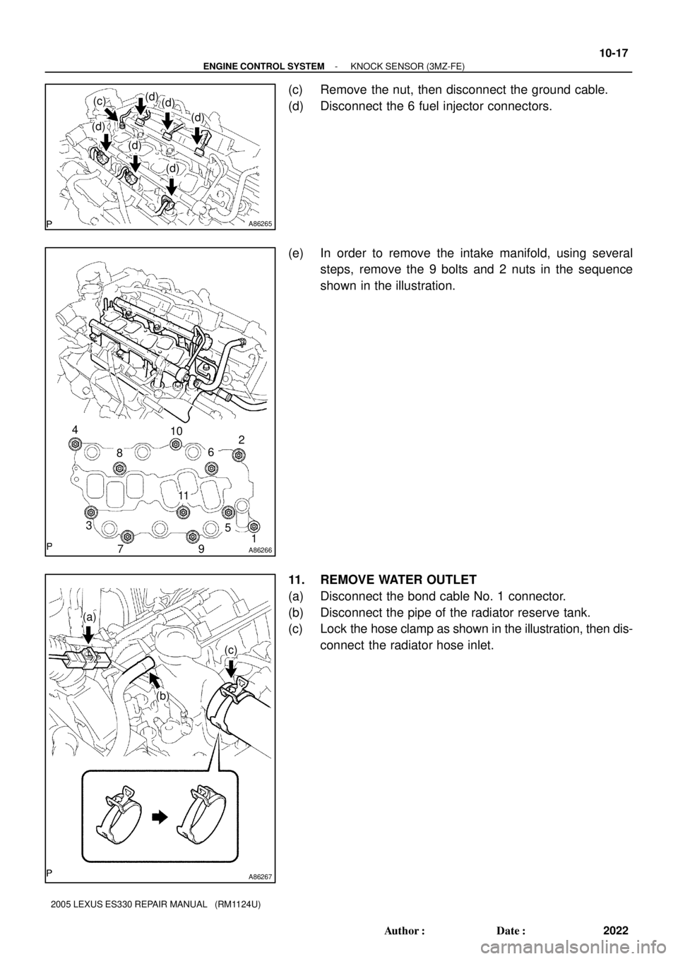
(c) Remove the nut, then disconnect the ground cable.
(d) Disconnect the 6 fuel injector connectors.
(e) In order to remove the intake manifold, using several
steps, remove the 9 bolts and 2 nuts in the sequence
shown in the illustration.
11. REMOVE WATER OUTLET
(a) Disconnect the bond cable No. 1 connector.
(b) Disconnect the pipe of the radiator reserve tank.
(c) Lock the hose clamp as shown in the illustration, then dis-
connect the radiator hose inlet.
Page 575 of 969

(e)
(f)
(f)
(f)
(f)
(g)
A79749
(a)
(b)
(a)
(b)
A79750
Upper
Engine
Front0 to 5� 10-18
- ENGINE CONTROL SYSTEMKNOCK SENSOR (3MZ-FE)
2023 Author�: Date�:
2005 LEXUS ES330 REPAIR MANUAL (RM")
A86268
(d)
(e)
(f)
(f)
(f)
(f)
(g)
A79749
(a)
(b)
(a)
(b)
A79750
Upper
Engine
Front0 to 5� 10-18
- ENGINE CONTROL SYSTEMKNOCK SENSOR (3MZ-FE)
2023 Author�: Date�:
2005 LEXUS ES330 REPAIR MANUAL (RM1124U)
(d) Disconnect the engine coolant temperature sensor con-
nector.
(e) Remove the clamp.
(f) Remove the 2 bolts, 2 nuts and 2 washers.
(g) Lock the hose clamp as shown in the illustration. Then re-
move the water outlet together with water by-pass hose
No. 1.
(h) Remove the 2 gaskets from the 2 cylinder heads.
12. REMOVE KNOCK SENSOR
(a) Disconnect the 2 knock sensor connectors.
(b) Remove the 2 nuts, then remove the 2 knock sensors.
13. INSTALL KNOCK SENSOR
(a) Install the 2 knock sensors with the 2 nuts as shown in the
illustration.
Torque: 20 NVm (204 kgfVcm, 14 ftVlbf)
(b) Connect the 2 knock sensor connectors.
14. INSTALL WATER OUTLET
(a) Install 2 new gaskets to the 2 cylinder heads.
(b) Install the water outlet together with water by-pass hose No. 1, then unlock the hose clamp.
(c) Tighten the 2 bolts, 2 nuts and 2 washers.
Torque: 15 NVm (153 kgfVcm, 11 ftVlbf)
(d) Install the clamp.
(e) Connect the engine coolant temperature sensor connector.
(f) Connect the bond cable No. 3 connector.
(g) Connect the pipe of the radiator reserve tank.
(h) Connect the radiator hose inlet, then unlock the hose clamp.
Page 581 of 969

11-1
2029 Author�: Date�:
2005 LEXUS ES330 REPAIR MANUAL (RM1124U)
FUEL SYSTEM (3MZ-FE)
PRECAUTION
1. PRECAUTION
(a) Before working o")
110XR-01
A62391
Circuit Opening Relay
- FUELFUEL SYSTEM (3MZ-FE)
11-1
2029 Author�: Date�:
2005 LEXUS ES330 REPAIR MANUAL (RM1124U)
FUEL SYSTEM (3MZ-FE)
PRECAUTION
1. PRECAUTION
(a) Before working on the fuel system, disconnect the engine wire No. 3 (battery negative terminal) from
battery.
(b) Do not smoke or work near open flame when working on the fuel system.
(c) Keep gasoline away from the rubber or leather parts.
2. DISCHARGE FUEL SYSTEM PRESSURE
CAUTION:
�Do not disconnect any parts of the fuel system pres-
sure until you have discharging the fuel system pres-
sure.
�Even after discharge the fuel pressure, place a shop
rag over fittings as you separate them in order to re-
duce risk of fuel spray on yourself or in the engine
compartment.
(a) Disconnect the engine wire No. 3 (battery negative termi-
nal).
(b) Remove the circuit opening relay from the engine room
relay block.
(c) Connect the engine wire No. 3 (battery negative terminal).
Torque: 5.4 NVm (55 kgfVcm, 48 in.Vlbf)
(d) Start the engine. After the engine has stopped on its own,
turn the ignition switch OFF.
HINT:
There is a case that DTC P0171 (system to lean) is output.
(e) Check that the engine does not start.
(f) Remove the fuel tank cap, then let the air out of the fuel
tank.
(g) Disconnect battery negative terminal.
(h) Reinstall the circuit opening relay.
3. FUEL SYSTEM
(a) When disconnecting the high fuel pressure line, a large
amount of gasoline will spill out. So observe these proce-
dures.
(1) Work in order to prevent gasoline from spilling out.
(2) Disconnect the fuel pump tube (see page 11-20).
(3) Drain the fuel remaining inside the fuel pump tube.