Page 636 of 969
120BZ-01
A86359
(a)
(b)
A86353
(c)
SST
A86353
SST
- EMISSION CONTROLAIR FUEL RATIO SENSOR (3MZ-FE (LH BANK))
12-23
2084 Author�: Date�:
2005 LEXUS ES330 REPAIR MANUAL (RM1124U)
AIR FUEL RATIO SENSOR (3MZ-FE (LH BANK))
REPLACEMENT
1. DISCONNECT ENGINE WIRE NO. 3 (BATTERY NEGATIVE TERMINAL)
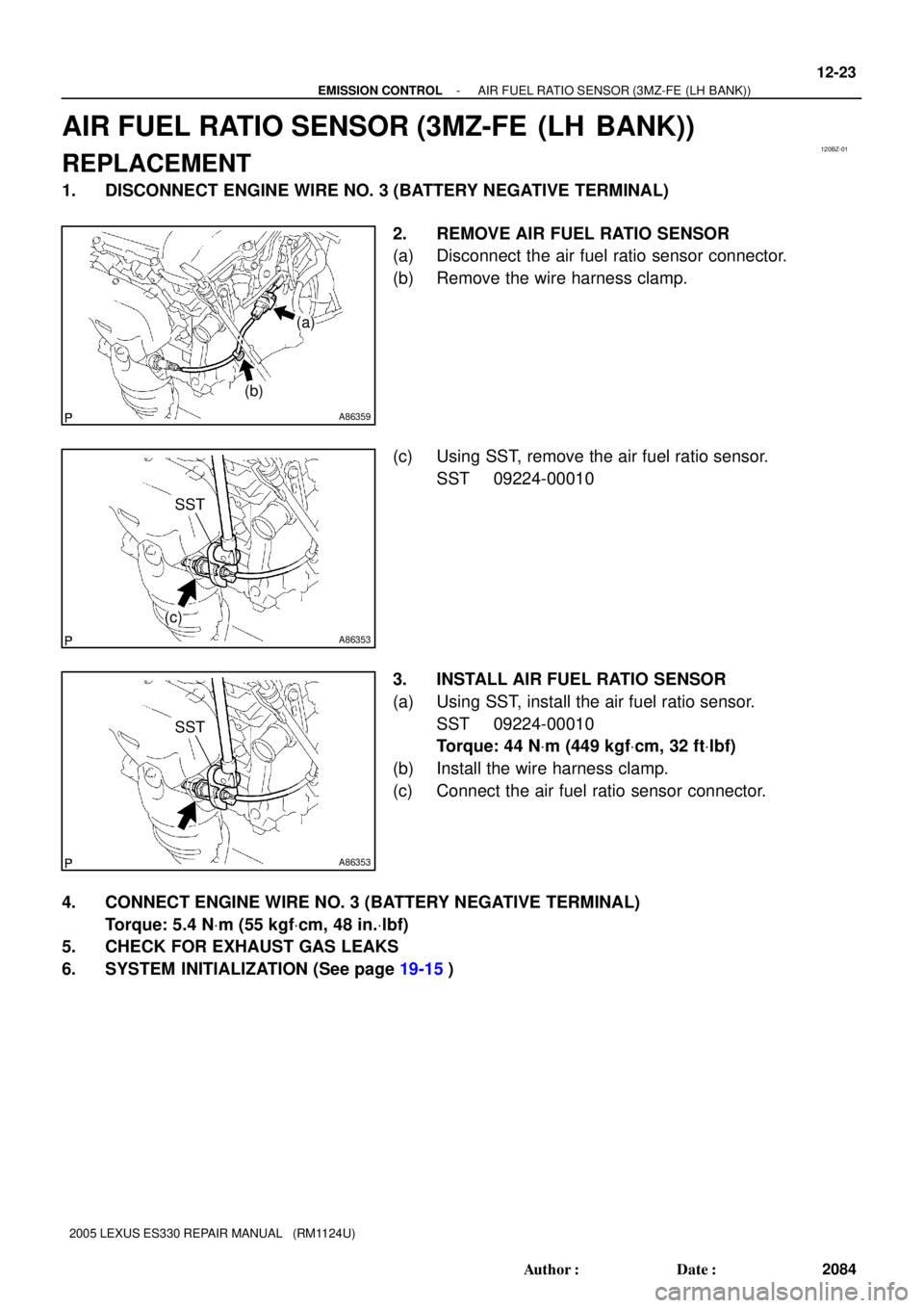
2. REMOVE AIR FUEL RATIO SENSOR
(a) Disconnect the air fuel ratio sensor connector.
(b) Remove the wire harness clamp.
(c) Using SST, remove the air fuel ratio sensor.
SST 09224-00010
3. INSTALL AIR FUEL RATIO SENSOR
(a) Using SST, install the air fuel ratio sensor.
SST 09224-00010
Torque: 44 NVm (449 kgfVcm, 32 ftVlbf)
(b) Install the wire harness clamp.
(c) Connect the air fuel ratio sensor connector.
4. CONNECT ENGINE WIRE NO. 3 (BATTERY NEGATIVE TERMINAL)
Torque: 5.4 NVm (55 kgfVcm, 48 in.Vlbf)
5. CHECK FOR EXHAUST GAS LEAKS
6. SYSTEM INITIALIZATION (See page 19-15)
Page 637 of 969
120BZ-01
A86359
(a)
(b)
A86353
(c)
SST
A86353
SST
- EMISSION CONTROLAIR FUEL RATIO SENSOR (3MZ-FE (LH BANK))
12-23
2084 Author�: Date�:
2005 LEXUS ES330 REPAIR MANUAL (RM1124U)
AIR FUEL RATIO SENSOR (3MZ-FE (LH BANK))
REPLACEMENT
1. DISCONNECT ENGINE WIRE NO. 3 (BATTERY NEGATIVE TERMINAL)
2. REMOVE AIR FUEL RATIO SENSOR
(a) Disconnect the air fuel ratio sensor connector.
(b) Remove the wire harness clamp.
(c) Using SST, remove the air fuel ratio sensor.
SST 09224-00010
3. INSTALL AIR FUEL RATIO SENSOR
(a) Using SST, install the air fuel ratio sensor.
SST 09224-00010
Torque: 44 NVm (449 kgfVcm, 32 ftVlbf)
(b) Install the wire harness clamp.
(c) Connect the air fuel ratio sensor connector.
4. CONNECT ENGINE WIRE NO. 3 (BATTERY NEGATIVE TERMINAL)
Torque: 5.4 NVm (55 kgfVcm, 48 in.Vlbf)
5. CHECK FOR EXHAUST GAS LEAKS
6. SYSTEM INITIALIZATION (See page 19-15)
Page 645 of 969
150B7-01
A86208
N´m (kgf´cm, ft´lbf)
: Specified torque
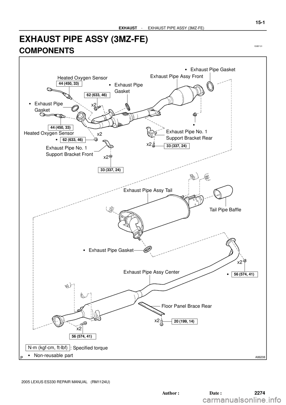
� Non-reusable part � Exhaust Pipe
Gasket
44 (450, 33)
Heated Oxygen Sensor
44 (450, 33)
Heated Oxygen Sensor
�
�
62 (633, 46)
Exhaust Pipe No. 1
Support Bracket Front
33 (337, 24)
Exhaust Pipe No. 1
Support Bracket Rear
33 (337, 24)
x2
x2
x2
Exhaust Pipe Assy Tail
Tail Pipe Baffle
Exhaust Pipe Assy Center
x2
x2
x2
20 (199, 14)
x2
56 (574, 41)
Floor Panel Brace Rear
� Exhaust Pipe Gasket� Exhaust Pipe Gasket
� Exhaust Pipe
Gasket
Exhaust Pipe Assy Front
�56 (574, 41)
62 (633, 46)
- EXHAUSTEXHAUST PIPE ASSY (3MZ-FE)
15-1
2274 Author�: Date�:
2005 LEXUS ES330 REPAIR MANUAL (RM1124U)
EXHAUST PIPE ASSY (3MZ-FE)
COMPONENTS
Page 646 of 969
150B8-01
A86209
A86210
(a)
(b)
(a)
(b)
(b)
A86211
Plastic-faced Hammer
15-2
- EXHAUSTEXHAUST PIPE ASSY (3MZ-FE)
2275 Author�: Date�:
2005 LEXUS ES330 REPAIR MANUAL (RM1124U)
Removal & Installation and Disassembly & Reassembly
1. DISCONNECT ENGINE WIRE NO. 3 (BATTERY NEGATIVE TERMINAL)
2. REMOVE HEATED OXYGEN SENSOR (See page 12-24)
SST 09224-00010
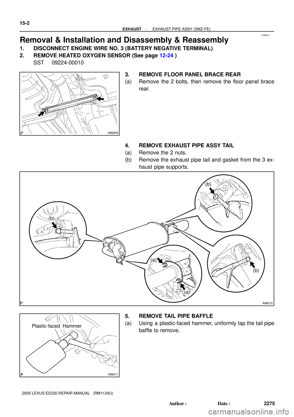
3. REMOVE FLOOR PANEL BRACE REAR
(a) Remove the 2 bolts, then remove the floor panel brace
rear.
4. REMOVE EXHAUST PIPE ASSY TAIL
(a) Remove the 2 nuts.
(b) Remove the exhaust pipe tail and gasket from the 3 ex-
haust pipe supports.
5. REMOVE TAIL PIPE BAFFLE
(a) Using a plastic-faced hammer, uniformly tap the tail pipe
baffle to remove.
Page 649 of 969
A86216
Keyway
KeyPlastic-faced
Hammer
- EXHAUSTEXHAUST PIPE ASSY (3MZ-FE)
15-5
2278 Author�: Date�:
2005 LEXUS ES330 REPAIR MANUAL (RM1124U)
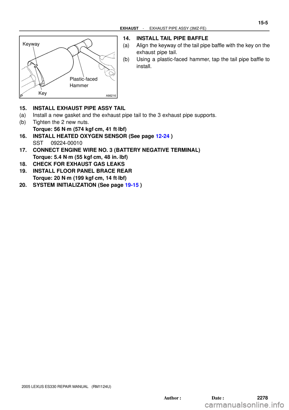
14. INSTALL TAIL PIPE BAFFLE
(a) Align the keyway of the tail pipe baffle with the key on the
exhaust pipe tail.
(b) Using a plastic-faced hammer, tap the tail pipe baffle to
install.
15. INSTALL EXHAUST PIPE ASSY TAIL
(a) Install a new gasket and the exhaust pipe tail to the 3 exhaust pipe supports.
(b) Tighten the 2 new nuts.
Torque: 56 NVm (574 kgfVcm, 41 ftVlbf)
16. INSTALL HEATED OXYGEN SENSOR (See page 12-24)
SST 09224-00010
17. CONNECT ENGINE WIRE NO. 3 (BATTERY NEGATIVE TERMINAL)
Torque: 5.4 NVm (55 kgfVcm, 48 in.Vlbf)
18. CHECK FOR EXHAUST GAS LEAKS
19. INSTALL FLOOR PANEL BRACE REAR
Torque: 20 NVm (199 kgfVcm, 14 ftVlbf)
20. SYSTEM INITIALIZATION (See page 19-15)
Page 667 of 969
160QJ-01
A86584: Specified torque Battery Clamp
Sub-assy
Battery
Battery Tray
VSV Connector
Air Cleaner
Inlet Assy
Air Cleaner Inlet
No. 1
Air Cleaner BracketAir Cleaner Case Air Cleaner
Filter Element
Sub-assyAir Cleaner Cap
Sub-assy Mass
Air Flow Sensor
Connector Vacuum Hose
5.0 (51, 44 in.Vlbf)
x2
x2 x3
5.0 (51, 44 in.Vlbf)
5.0 (51, 44 in.Vlbf)
Air Cleaner Hose No. 1
N´m (kgf´cm, ft´lbf)Vacuum Hose
5.0 (51, 44 in.Vlbf)
Radiator Lower Air Deflector
Clip
x7
Clip
Engine Under Cover No. 2
Engine Under Cover No. 1
5.5 (56, 49 in.Vlbf)
7.5 (76, 66 in.Vlbf)
16-18
- COOLINGRADIATOR ASSY (3MZ-FE)
2296 Author�: Date�:
2005 LEXUS ES330 REPAIR MANUAL (RM1124U)
RADIATOR ASSY (3MZ-FE)
COMPONENTS
Page 683 of 969
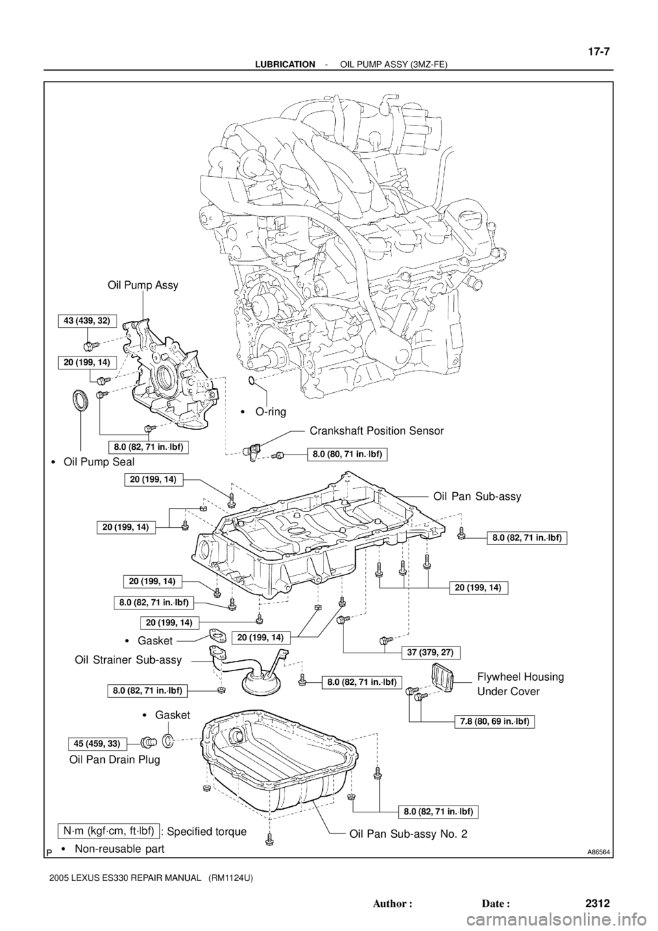
A86564
N´m (kgf´cm, ft´lbf)
: Specified torque
� Non-reusable part� Gasket� O-ring
� Oil Pump Seal
20 (199, 14)
20 (199, 14)
20 (199, 14)
8.0 (82, 71 in.Vlbf)
20 (199, 14)
20 (199, 14)
8.0 (82, 71 in.Vlbf)
45 (459, 33)
� Gasket
8.0 (82, 71 in.Vlbf)
7.8 (80, 69 in.Vlbf)
8.0 (82, 71 in.Vlbf)
37 (379, 27)
20 (199, 14)
8.0 (82, 71 in.Vlbf)
8.0 (80, 71 in.Vlbf)
Crankshaft Position Sensor
Oil Pan Sub-assy
Oil Strainer Sub-assy
Oil Pan Drain Plug
Oil Pan Sub-assy No. 2Flywheel Housing
Under Cover
43 (439, 32)
8.0 (82, 71 in.Vlbf)
20 (199, 14)
Oil Pump Assy
- LUBRICATIONOIL PUMP ASSY (3MZ-FE)
17-7
2312 Author�: Date�:
2005 LEXUS ES330 REPAIR MANUAL (RM1124U)
Page 687 of 969
A52015
A36750
A00019
SST
SST
A78379
- LUBRICATIONOIL PUMP ASSY (3MZ-FE)
17-1 1
2316 Author�: Date�:
34. REMOVE ENGINE MOUNTING BRACKET RH
(a) Remove the 4 bolts and nut, then remove the bracket.
35. REMOVE OIL PAN SUB-ASSY NO.2
(a) Remove the 10 bolts and 2 nuts.
(b) Insert the blade of SST between the oil pan No. 1 and oil
pan No. 2, then cut off the sealer and remove the oil pan
No. 2.
SST 09032-00100
NOTICE:
�Be careful not to damage the contact surface of the oil
pan No. 1 where the oil pan No. 2 is mounted.
�Do not damage the flange portion of the oil pan No. 2
when removing.
36. REMOVE OIL STRAINER SUB-ASSY
(a) Remove the bolt and 2 nuts, then remove the oil strainer and gasket.
37. REMOVE OIL PAN SUB-ASSY
(a) Remove the 2 bolts and nut, then disconnect the engine
oil level sensor connector.
(b) Remove the 2 bolts and flywheel housing under cover.