Page 688 of 969
A36754
B04137
A51990
A78754
SST 17-12
- LUBRICATIONOIL PUMP ASSY (3MZ-FE)
2317 Author�: Date�:
(c) Loosen and remove the 17 bolts and 2 nuts uniformly.
(d) Using a screwdriver, remove the oil pan by prying be-
tween the cylinder block and oil pan.
NOTICE:
Be careful not to damage the contact surfaces of the oil pan
and cylinder block.
38. REMOVE CRANKSHAFT POSITION SENSOR
(a) Disconnect the crankshaft position sensor connector.
(b) Remove the bolt and crankshaft position sensor.
39. REMOVE OIL PUMP ASSY
(a) Remove the 9 bolts.
(b) Using a screwdriver, remove the oil pump by prying be-
tween the oil pump and bearing cap.
(c) Remove the O-ring.
40. INSTALL OIL PUMP SEAL
(a) Using SST and a hammer, tap in the new oil seal until its
surface is flush with the oil pump body edge.
SST 09223-00010
NOTICE:
�Be careful not to tap the oil seal at an angle.
�Keep the lip free of foreign objects.
(b) Apply multi-purpose grease to the oil seal lip.
Page 690 of 969
 AAB
B Region ºXº Region ºYº 17-14
- LUBRICATIONOIL PUMP ASSY (3MZ-FE)
2319 Author�: Date�:
(e) Install the oi")
A51990
A
B
C
B
A
A
A
A
A
A78726
Seal Packing
Seal Width
3 to 4 mm
(0.12 to 0.16 in.) AAB
B Region ºXº Region ºYº 17-14
- LUBRICATIONOIL PUMP ASSY (3MZ-FE)
2319 Author�: Date�:
(e) Install the oil pump with the 9 bolts. Tighten the bolts uni-
formly in several steps.
Torque:
8.0 NVm (82 kgfVcm, 71 in.Vlbf) for bolt A
20 NVm (199 kgfVcm, 14 ftVlbf) for bolt B
43 NVm (439 kgfVcm, 32 ftVlbf) for bolt C
42. INSTALL CRANKSHAFT POSITION SENSOR
Torque: 8.0 NVm (80 kgfVcm, 71 in.Vlbf)
43. INSTALL OIL PAN SUB-ASSY
(a) Remove any old seal packing from the contact surface.
(b) Apply a continuous bead of seal packing (Diameter 3 to
4 mm (0.12 to 0.16 in.)) as shown in the illustration.
Seal packing: Part No. 08826-00080 or equivalent
NOTICE:
�Remove any oil from the contact surface.
�Apply seal packing to the outer side of the bolt holes
in the region ºXº.
�Apply seal packing to the inner side of the bolt holes
in the region ºYº.
�Install the oil pan within 3 minutes after applying seal
packing.
�Do not expose the seal packing to engine oil within 2
hours after installing.
(c) Install the oil pan with the 17 bolts and 2 nuts. Tighten the
bolts uniformly in several steps.
Torque:
8.0 NVm (82 kgfVcm, 71 in.Vlbf) for 10 mm head
20 NVm (199 kgfVcm, 14 ftVlbf) for 12 mm head
37 NVm (379 kgfVcm, 27 ftVlbf) for 14 mm head
(d) Install the flywheel housing under cover with the 2 bolts.
Torque: 7.8 NVm (80 kgfVcm, 69 in.Vlbf)
(e) Install the engine oil level sensor connector with the 2
bolts and nut.
Torque: 8.4 NVm (85 kgfVcm, 74 in.Vlbf)
44. INSTALL OIL STRAINER SUB-ASSY
(a) Install a new gasket and the oil strainer with the bolt and 2 nuts.
Torque: 8.0 NVm (82 kgfVcm, 71 in.Vlbf)
Page 698 of 969
18-2
- IGNITIONIGNITION SYSTEM (3MZ-FE)
2327 Author�: Date�:
2005 LEXUS ES330 REPAIR MANUAL (RM1124U)
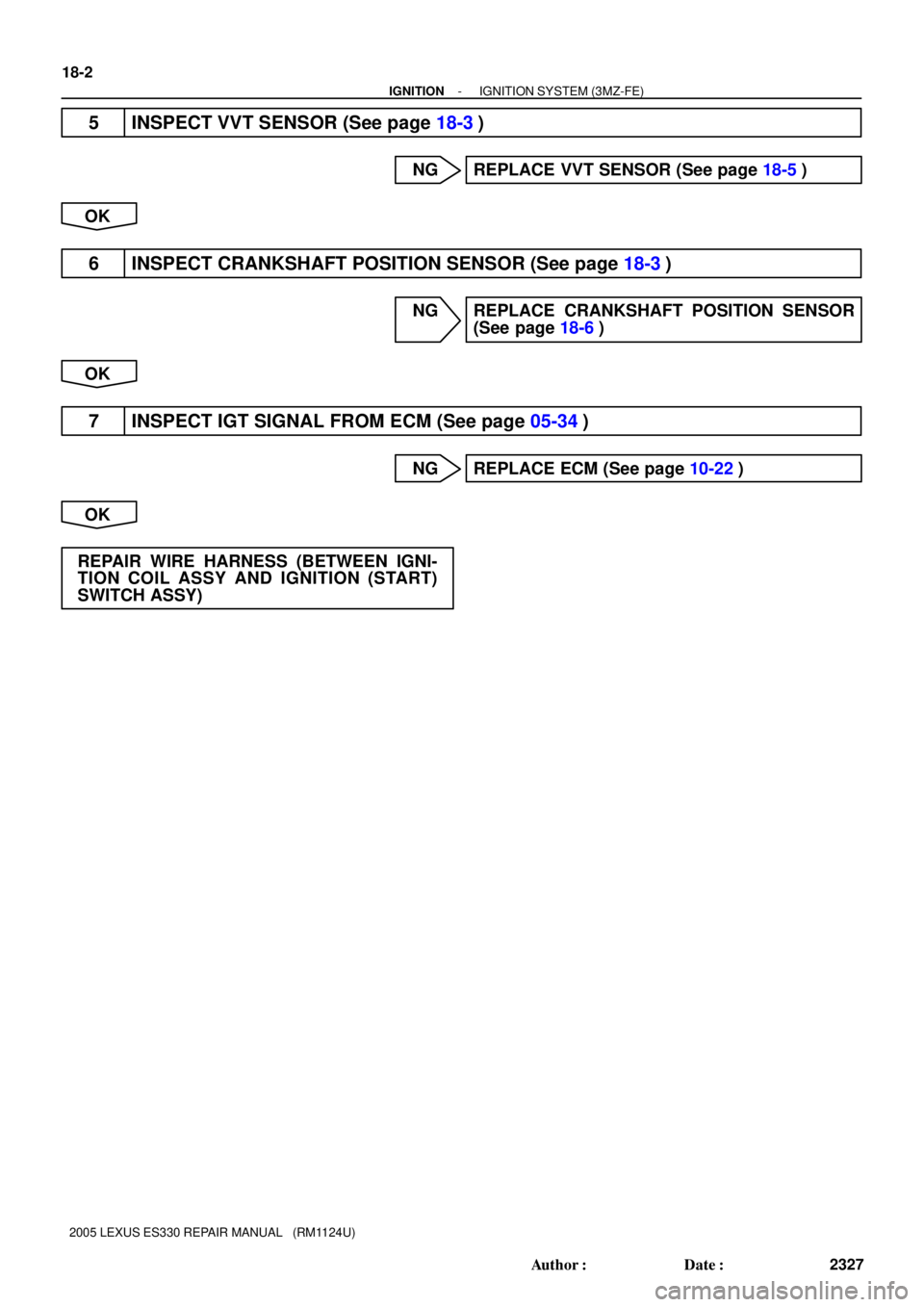
5 INSPECT VVT SENSOR (See page 18-3)
NG REPLACE VVT SENSOR (See page 18-5)
OK
6 INSPECT CRANKSHAFT POSITION SENSOR (See page 18-3)
NG REPLACE CRANKSHAFT POSITION SENSOR
(See page 18-6)
OK
7 INSPECT IGT SIGNAL FROM ECM (See page 05-34)
NG REPLACE ECM (See page 10-22)
OK
REPAIR WIRE HARNESS (BETWEEN IGNI-
TION COIL ASSY AND IGNITION (START)
SWITCH ASSY)
Page 700 of 969

2329 Author�: Date�:
2005 LEXUS ES330 REPAIR MANUAL (RM1124U)
(e) Clean the spark plugs.
If the electrode has traces of")
B62019
A84690
Ohmmeter
A84688
Ohmmeter 18-4
- IGNITIONIGNITION SYSTEM (3MZ-FE)
2329 Author�: Date�:
2005 LEXUS ES330 REPAIR MANUAL (RM1124U)
(e) Clean the spark plugs.
If the electrode has traces of wet carbon, clean the electrode
with a spark plug cleaner, then dry it.
Air pressure: Blow 588 kPa (6 kgf/cm
2, 85 psi)
Duration: 20 seconds or shorter
If there are traces of oil, remove it with gasoline before using the
spark plug cleaner.
2. INSPECT VVT SENSOR
(a) Inspect the resistance.
(1) Using an ohmmeter, measure the resistance be-
tween the terminals.
Resistance:
Tester ConnectionSpecified Condition
1 (G+) - 2 (G-)835 to 1,400 W at cold
1 (G+) - 2 (G-)1,060 to 1,645 W at hot
NOTICE:
ºColdº and ºHotº mean temperature of the coils them-
selves. ºColdº is from -10�C (14�F) to 50�C (122�F) and
ºHotº is from 50�C (122�F) to 100�C (212�F).
If the resistance is not as specified, replace the VVT sensor.
3. INSPECT CRANKSHAFT POSITION SENSOR
(a) Inspect the resistance.
(1) Using an ohmmeter, measure the resistance be-
tween the terminals.
Resistance:
Tester ConnectionSpecified Condition
1 (NE+) - 2 (NE-)1,630 to 2,740 W at cold
1 (NE+) - 2 (NE-)2,065 to 3,225 W at hot
NOTICE:
ºColdº and ºHotº mean temperature of the coils them-
selves. ºColdº is from -10�C (14�F) to 50�C (122�F) and
ºHotº is from 50�C (122�F) to 100�C (212�F).
If the resistance is not as specified, replace the crankshaft posi-
tion sensor.
Page 701 of 969

(b)
A78529
LH Bank:
(a)
(b)
- IGNITIONVVT SENSOR (3MZ-FE)
18-5
2330 Author�: Date�:
2005 LEXUS ES330 REPAIR MANUAL (RM1124U)
VVT SENSOR (3MZ-FE)
REPLACEMENT
1. DISCONNEC")
1809C-01
A79541
RH Bank:
(a)
(b)
A78529
LH Bank:
(a)
(b)
- IGNITIONVVT SENSOR (3MZ-FE)
18-5
2330 Author�: Date�:
2005 LEXUS ES330 REPAIR MANUAL (RM1124U)
VVT SENSOR (3MZ-FE)
REPLACEMENT
1. DISCONNECT ENGINE WIRE NO. 3 (BATTERY NEGATIVE TERMINAL)
2. REMOVE RADIATOR LOWER AIR DEFLECTOR (See page 19-5)
3. REMOVE AIR CLEANER INLET ASSY (See page 19-5)
4. REMOVE AIR CLEANER ASSY (See page 19-5)
5. REMOVE VVT SENSOR
(a) Remove the 2 VVT sensor connectors.
(b) Remove the 2 bolts, then remove the 2 VVT sensors.
HINT:
The VVT sensor is installed with the bolt.
6. INSTALL VVT SENSOR
(a) Apply a light coat of engine oil to the O-ring on each VVT sensor.
(b) Install the 2 VVT sensors with the 2 bolts.
Torque: 8.0 NVm (80 kgfVcm, 71 in.Vlbf)
NOTICE:
Be careful not to twist the O-ring.
(c) Connect the 2 VVT sensor connectors.
7. INSTALL AIR CLEANER ASSY (See page 19-5)
8. INSTALL AIR CLEANER INLET ASSY (See page 19-5)
9. INSTALL RADIATOR LOWER AIR DEFLECTOR
10. CHECK CONNECTION OF VACUUM HOSE (See page 14-29)
11. CONNECT ENGINE WIRE NO. 3 (BATTERY NEGATIVE TERMINAL)
Torque: 5.4 NVm (55 kgfVcm, 48 in.Vlbf)
12. CHECK FOR ENGINE OIL LEAKS
13. SYSTEM INITIALIZATION (See page 19-15)
Page 702 of 969
1809D-01
A86232
A86233
A79763
(a)
(b) 18-6
- IGNITIONCRANKSHAFT POSITION SENSOR (3MZ-FE)
2331 Author�: Date�:
2005 LEXUS ES330 REPAIR MANUAL (RM1124U)
CRANKSHAFT POSITION SENSOR (3MZ-FE)
REPLACEMENT
1. DISCONNECT ENGINE WIRE NO. 3 (BATTERY NEGATIVE TERMINAL)
2. REMOVE ENGINE UNDER COVER NO.1
(a) Remove the 3 clips and 5 screws, then remove the engine
under cover No. 1.
3. REMOVE FRONT FENDER APRON SEAL RH
(a) Remove the clip and 2 bolts, then remove the front fender
apron seal.
4. REMOVE CRANKSHAFT POSITION SENSOR
(a) Remove the crankshaft position sensor connector.
(b) Remove the bolt, then remove the crankshaft position
sensor.
5. INSTALL CRANKSHAFT POSITION SENSOR
Torque: 8.0 NVm (80 kgfVcm, 71 in.Vlbf)
6. INSTALL FRONT FENDER APRON SEAL RH
7. INSTALL ENGINE UNDER COVER NO.1
8. CONNECT ENGINE WIRE NO. 3 (BATTERY NEGATIVE TERMINAL)
Torque: 5.4 NVm (55 kgfVcm, 48 in.Vlbf)
9. SYSTEM INITIALIZATION (See page 19-15)
Page 706 of 969
2601C-06
C93850
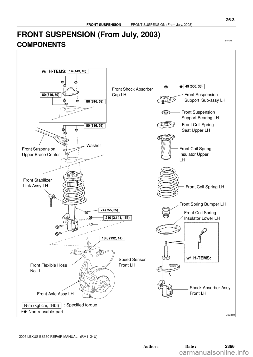
N´m (kgf´cm, ft´lbf): Specified torque
� Non-reusable part�
Front Suspension
Support Sub-assy LH
Front Suspension
Support Bearing LH
Front Coil Spring
Seat Upper LH
Front Coil Spring
Insulator Upper
LH
Front Coil Spring LH
Front Spring Bumper LH
Front Coil Spring
Insulator Lower LH
Shock Absorber Assy
Front LH Front Stabilizer
Link Assy LH
Front Flexible Hose
No. 1
74 (755, 55)
Speed Sensor
Front LH
Front Axle Assy LH
49 (500, 36)
18.8 (192, 14)
14 (143, 10)
80 (816, 59)
w/ H-TEMS: w/ H-TEMS:
Front Shock Absorber
Cap LH
80 (816, 59)
80 (816, 59)
Front Suspension
Upper Brace CenterWasher
210 (2,141, 155)
- FRONT SUSPENSIONFRONT SUSPENSION (From July, 2003)
26-3
2366 Author�: Date�:
2005 LEXUS ES330 REPAIR MANUAL (RM1124U)
FRONT SUSPENSION (From July, 2003)
COMPONENTS
Page 707 of 969
C93097
74 (755, 55)
Front Stabilizer
Link Assy RH
Stabilizer Bar FrontFront Stabilizer Bracket No. 1 RH
Front Stabilizer Bar Bush No. 1
Front Stabilizer Bracket No. 1 LH
Front Stabilizer Link Assy LH
Rack & Pinion Power
Steering Gear Assy
Speed Sensor
Front LH
Front Frame Assy
Front Lower Arm
Bush Stopper
Lower Ball Joint
Assy Front LH
Front Suspension
Arm Sub-assy
Lower No. 1 LHFront Brake
Caliper Assy
Front Axle Assy LH �Cotter Pin
19 (194, 14)
�Cotter Pin
N´m (kgf´cm, ft´lbf): Specified torque
� Non-reusable part
Front Disc
74 (755, 55)
74 (755, 55)
206 (2,101, 152)
294 (2,998, 217)
49 (500, 36)
87 (887, 64)
123 (1,254 91)
200 (2,039, 148)
200 (2,039, 148)
75 (765, 55)
70 (714, 52)
70 (714, 52)
8.0 (82, 71 in.Vlbf)
106.9 (1,090, 79)
106.9 (1,090, 79)
19 (194, 14)
�
210 (2,141, 155)
95 (969, 70)
Transverse Engine
Engine Mounting
Insulator
26-4
- FRONT SUSPENSIONFRONT SUSPENSION (From July, 2003)
2367 Author�: Date�:
2005 LEXUS ES330 REPAIR MANUAL (RM1124U)


Front Stabilizer
Link Assy RH
Stabilizer Bar FrontFront Stabilizer Bracket No. 1 RH
Front Stabilizer Bar Bush No. 1
Front Stabilizer Bracket No. 1 LH
Front Stabilizer Link Assy LH")