Page 56 of 969
 ISC
Idle Speed Control-
KSKnock SensorKnock Sensor
MAFMass Air FlowAir Flow M")
01-8- INTRODUCTIONTERMS FOR AUTOMATIC TRANSAXLE REPAIR
MANUAL
8 Author�: Date�:
U151E, U151F A/T REPAIR MANUAL (RM1021U) ISC
Idle Speed Control-
KSKnock SensorKnock Sensor
MAFMass Air FlowAir Flow Meter
MAPManifold Absolute PressureManifold Pressure
Intake Vacuum
MCMixture Control
Electric Bleed Air Control Valve (EBCV)
Mixture Control Valve (MCV)
Electric Air Control Valve (EACV)
MDPManifold Differential Pressure-
MFIMultiport Fuel InjectionElectronic Fuel Injection (EFI)
MILMalfunction Indicator LampCheck Engine Light
MSTManifold Surface temperature-
MVZManifold Vacuum Zone-
NVRAMNon-V olatile Random Access Memory-
O2SOxygen SensorOxygen Sensor, O2 Sensor (O2S)
OBDOn-Board DiagnosticOn-Board Diagnostic (OBD)
OCOxidation Catalytic ConverterOxidation Catalyst Converter (OC), CC0
OPOpen LoopOpen Loop
PAIRPulsed Secondary Air InjectionAir Suction (AS)
PCMPowertrain Control Module-
PNPPark/Neutral Position-
PROMProgrammable Read Only Memory-
PSPPower Steering Pressure-
PTOXPeriodic Trap OxidizerDiesel Particulate Filter (DPF)
Diesel Particulate Trap (DPT)
RAMRandom Access MemoryRandom Access Memory (RAM)
RMRelay Module-
ROMRead Only MemoryRead Only Memory (ROM)
RPMEngine SpeedEngine Speed
SCSuperchargerSupercharger
SCBSupercharger Bypass-
SFISequential Multiport Fuel InjectionElectronic Fuel Injection (EFI), Sequential Injection
SPLSmoke Puff Limiter-
SRIService Reminder Indicator-
SRTSystem Readiness Test-
STScan Tool-
TBThrottle BodyThrottle Body
TBIThrottle Body Fuel InjectionSingle Point Injection
Central Fuel Injection (Ci)
TCTurbochargerTurbocharger
TCCTorque Converter ClutchTorque Converter
TCMTransmission Control ModuleTransmission ECU (Electronic Control Unit)
TPThrottle PositionThrottle Position
TRTransmission Range-
TVVThermal Vacuum ValveBimetallic Vacuum Switching Valve (BVSV)
Thermostatic Vacuum Switching Valve (TVSV)
TWCThree-W ay Catalytic ConverterThree-W ay Catalytic (TWC)
CC
RO
TWC+OCThree-W ay + Oxidation Catalytic ConverterCCR + CCO
VA FVolume Air FlowAir Flow Meter
VRVoltage RegulatorVoltage Regulator
VSSVehicle Speed SensorVehicle Speed Sensor (Read Switch Type)
WOTWide Open ThrottleFull Throttle
Page 408 of 969
A78549
A52890
A78403
RH: LH:
A60501
14-32
- ENGINE MECHANICALPARTIAL ENGINE ASSY (3MZ-FE)
2124 Author�: Date�:
2005 LEXUS ES330 REPAIR MANUAL (RM1124U)
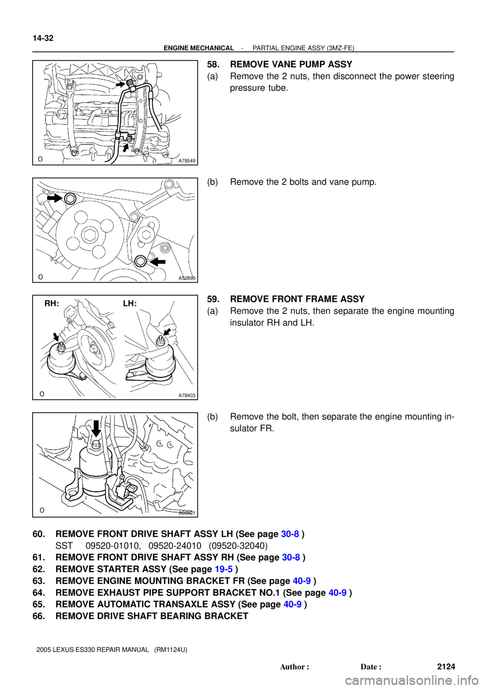
58. REMOVE VANE PUMP ASSY
(a) Remove the 2 nuts, then disconnect the power steering
pressure tube.
(b) Remove the 2 bolts and vane pump.
59. REMOVE FRONT FRAME ASSY
(a) Remove the 2 nuts, then separate the engine mounting
insulator RH and LH.
(b) Remove the bolt, then separate the engine mounting in-
sulator FR.
60. REMOVE FRONT DRIVE SHAFT ASSY LH (See page 30-8)
SST 09520-01010, 09520-24010 (09520-32040)
61. REMOVE FRONT DRIVE SHAFT ASSY RH (See page 30-8)
62. REMOVE STARTER ASSY (See page 19-5)
63. REMOVE ENGINE MOUNTING BRACKET FR (See page 40-9)
64. REMOVE EXHAUST PIPE SUPPORT BRACKET NO.1 (See page 40-9)
65. REMOVE AUTOMATIC TRANSAXLE ASSY (See page 40-9)
66. REMOVE DRIVE SHAFT BEARING BRACKET
Page 412 of 969
A78403
RH: LH:
A60501
A52890
A78549
14-36
- ENGINE MECHANICALPARTIAL ENGINE ASSY (3MZ-FE)
2128 Author�: Date�:
2005 LEXUS ES330 REPAIR MANUAL (RM1124U)
117. INSTALL FRONT DRIVE SHAFT ASSY LH (See page 30-8)
118. INSTALL FRONT DRIVE SHAFT ASSY RH (See page 30-8)
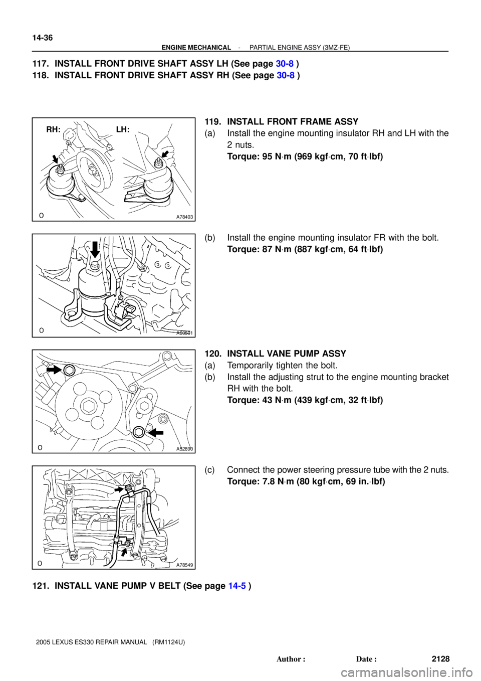
119. INSTALL FRONT FRAME ASSY
(a) Install the engine mounting insulator RH and LH with the
2 nuts.
Torque: 95 NVm (969 kgfVcm, 70 ftVlbf)
(b) Install the engine mounting insulator FR with the bolt.
Torque: 87 NVm (887 kgfVcm, 64 ftVlbf)
120. INSTALL VANE PUMP ASSY
(a) Temporarily tighten the bolt.
(b) Install the adjusting strut to the engine mounting bracket
RH with the bolt.
Torque: 43 NVm (439 kgfVcm, 32 ftVlbf)
(c) Connect the power steering pressure tube with the 2 nuts.
Torque: 7.8 NVm (80 kgfVcm, 69 in.Vlbf)
121. INSTALL VANE PUMP V BELT (See page 14-5)
Page 415 of 969
- ENGINE MECHANICALPARTIAL ENGINE ASSY (3MZ-FE)
14-39
2131 Author�: Date�:
2005 LEXUS ES330 REPAIR MANUAL (RM1124U)
157. ADD AUTOMATIC TRANSAXLE FLUID
158. ADD ENGINE OIL (See page 17-20)
159. ADD COOLANT (See page 16-9)
160. ADD POWER STEERING FLUID
161. BLEED POWER STEERING FLUID
162. INSPECT AUTOMATIC TRANSAXLE FLUID (See page 40-1)
163. CHECK FOR ENGINE OIL LEAKS
164. CHECK FOR ENGINE COOLANT LEAKS (See page 16-1)
165. CHECK POWER STEERING FLUID LEAKAGE
166. INSPECT FOR FUEL LEAKS
167. CHECK FOR EXHAUST GAS LEAKS
168. INSPECT AND ADJUST FRONT WHEEL ALIGNMENT (See page 26-5)
169. INSPECT STEERING WHEEL CENTER POINT
170. INSPECT IGNITION TIMING (See page 14-1)
SST 09843-18040
171. INSPECT ENGINE IDLE SPEED (See page 14-1)
172. INSPECT CO/HC (See page 14-1)
173. CHECK ABS SPEED SENSOR SIGNAL (See page 05-420, 05-471)
174. SYSTEM INITIALIZATION (See page 19-15)
Page 686 of 969
A78827Adjusting Bar Bracket
(b)
(a)
(a)
(b)
(b)
A36749
A60523
A86600
17-10
- LUBRICATIONOIL PUMP ASSY (3MZ-FE)
2315 Author�: Date�:
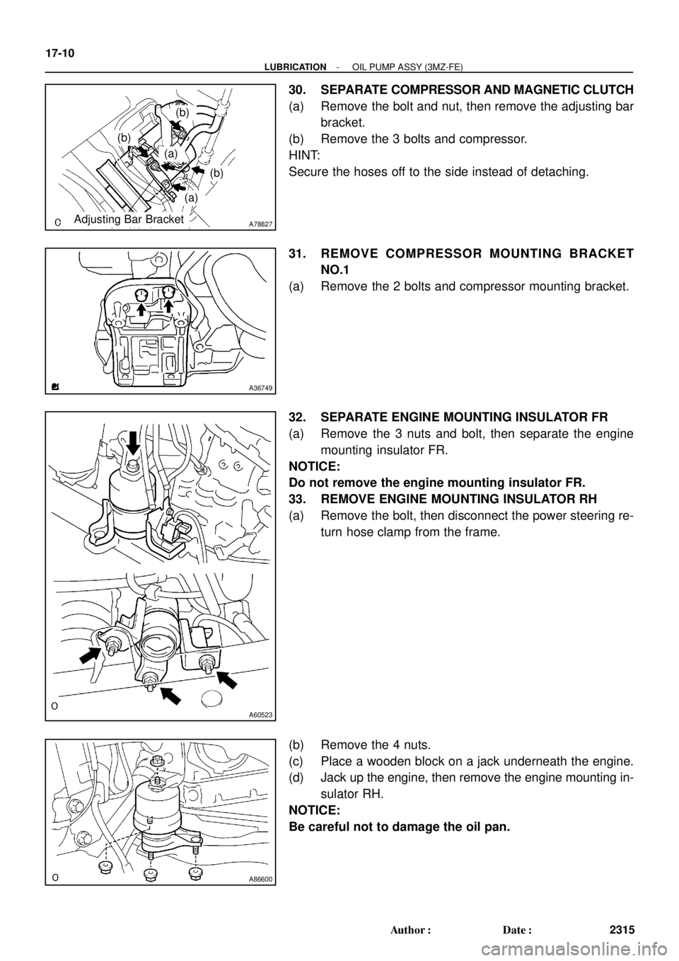
30. SEPARATE COMPRESSOR AND MAGNETIC CLUTCH
(a) Remove the bolt and nut, then remove the adjusting bar
bracket.
(b) Remove the 3 bolts and compressor.
HINT:
Secure the hoses off to the side instead of detaching.
31. REMOVE COMPRESSOR MOUNTING BRACKET
NO.1
(a) Remove the 2 bolts and compressor mounting bracket.
32. SEPARATE ENGINE MOUNTING INSULATOR FR
(a) Remove the 3 nuts and bolt, then separate the engine
mounting insulator FR.
NOTICE:
Do not remove the engine mounting insulator FR.
33. REMOVE ENGINE MOUNTING INSULATOR RH
(a) Remove the bolt, then disconnect the power steering re-
turn hose clamp from the frame.
(b) Remove the 4 nuts.
(c) Place a wooden block on a jack underneath the engine.
(d) Jack up the engine, then remove the engine mounting in-
sulator RH.
NOTICE:
Be careful not to damage the oil pan.
Page 707 of 969
C93097
74 (755, 55)
Front Stabilizer
Link Assy RH
Stabilizer Bar FrontFront Stabilizer Bracket No. 1 RH
Front Stabilizer Bar Bush No. 1
Front Stabilizer Bracket No. 1 LH
Front Stabilizer Link Assy LH
Rack & Pinion Power
Steering Gear Assy
Speed Sensor
Front LH
Front Frame Assy
Front Lower Arm
Bush Stopper
Lower Ball Joint
Assy Front LH
Front Suspension
Arm Sub-assy
Lower No. 1 LHFront Brake
Caliper Assy
Front Axle Assy LH �Cotter Pin
19 (194, 14)
�Cotter Pin
N´m (kgf´cm, ft´lbf): Specified torque
� Non-reusable part
Front Disc
74 (755, 55)
74 (755, 55)
206 (2,101, 152)
294 (2,998, 217)
49 (500, 36)
87 (887, 64)
123 (1,254 91)
200 (2,039, 148)
200 (2,039, 148)
75 (765, 55)
70 (714, 52)
70 (714, 52)
8.0 (82, 71 in.Vlbf)
106.9 (1,090, 79)
106.9 (1,090, 79)
19 (194, 14)
�
210 (2,141, 155)
95 (969, 70)
Transverse Engine
Engine Mounting
Insulator
26-4
- FRONT SUSPENSIONFRONT SUSPENSION (From July, 2003)
2367 Author�: Date�:
2005 LEXUS ES330 REPAIR MANUAL (RM1124U)
Page 720 of 969

STABILIZER BAR FRONT
REPLACEMENT
HINT:
COMPONENTS: See page 26-3.
1.")
2601J-17
F40143
C91607
- FRONT SUSPENSIONSTABILIZER BAR FRONT
26-17
2380 Author�: Date�:
2005 LEXUS ES330 REPAIR MANUAL (RM1124U)
STABILIZER BAR FRONT
REPLACEMENT
HINT:
COMPONENTS: See page 26-3.
1. REMOVE FRONT WHEEL
2. REMOVE FRONT STABILIZER LINK ASSY LH
(a) Remove the 2 nuts and front stabilizer link assy LH.
HINT:
If the ball joint turns together with the nut, use a hexagon (6 mm)
wrench to hold the stud.
3. REMOVE FRONT STABILIZER LINK ASSY RH
HINT:
Remove the RH side by the same procedures with the LH side.
4. REMOVE FRONT STABILIZER BRACKET NO.1 LH
(a) Remove the 2 bolts and 2 front stabilizer brackets No. 1
LH.
5. REMOVE FRONT STABILIZER BRACKET NO.1 RH
HINT:
Remove the RH side by the same procedures with the LH side.
6. DISCONNECT TIE ROD ASSY LH (See page 30-8)
SST 09628-6201 1
7. DISCONNECT TIE ROD ASSY RH
SST 09628-6201 1
HINT:
Separate the RH side by the same procedures with the LH side.
8. DISCONNECT STEERING GEAR OUTLET RETURN TUBE (See page 51-21)
SST 09023-00101
9. DISCONNECT PRESSURE FEED TUBE ASSY (See page 51-21)
SST 09023-00101
10. DISCONNECT STEERING INTERMEDIATE SHAFT SUB-ASSY (See page 51-21)
11. REMOVE RACK & PINION POWER STEERING GEAR ASSY (See page 51-21)
Page 721 of 969

12. REMOVE STABILIZER BAR FRONT
13. REMOVE")
C66721
C81547F40197
Inner side
Rear
side
C91607
26-18
- FRONT SUSPENSIONSTABILIZER BAR FRONT
2381 Author�: Date�:
2005 LEXUS ES330 REPAIR MANUAL (RM1124U)
12. REMOVE STABILIZER BAR FRONT
13. REMOVE FRONT STABILIZER BAR BUSH NO.1
14. INSPECT FRONT STABILIZER LINK ASSY LH
(a) As shown in the illustration, flip the ball joint stud back and
forth 5 times, before installing the nut.
(b) Using a torque wrench, turn the nut continuously at a rate
of 2 - 4 seconds per 1 turn and take the torque reading
on the 5th turn.
Turning torque:
0.05 - 1.96 N´m (0.5 - 20 kgf´cm, 0.4 - 17.4 in.´lbf)
15. INSTALL FRONT STABILIZER BAR BUSH NO.1
HINT:
Install the bushing to the inner side of the bushing stopper on
the stabilizer bar.
16. INSTALL STABILIZER BAR FRONT
17. INSTALL RACK & PINION POWER STEERING GEAR ASSY (See page 51-21)
18. INSTALL STEERING INTERMEDIATE SHAFT SUB-ASSY (See page 51-21)
19. INSTALL PRESSURE FEED TUBE ASSY (See page 51-21)
SST 09023-00101
20. INSTALL STEERING GEAR OUTLET RETURN TUBE (See page 51-21)
SST 09023-00101
21. INSTALL TIE ROD ASSY LH (See page 30-8)
22. INSTALL TIE ROD ASSY RH
HINT:
Install the RH side by the same procedures with the LH side.
23. INSTALL FRONT STABILIZER BRACKET NO.1 LH
(a) Install the 2 front stabilizer brackets No. 1 LH with the 2
bolts.
Torque: 19 NVm (194 kgfVcm, 14 ftVlbf)

Front Stabilizer
Link Assy RH
Stabilizer Bar FrontFront Stabilizer Bracket No. 1 RH
Front Stabilizer Bar Bush No. 1
Front Stabilizer Bracket No. 1 LH
Front Stabilizer Link Assy LH")