Page 65 of 133

JAGUARS-TYPEChassis
60
D.211.255
ELECTRICALLY ADJUSTABLE STEERING COLUMN
Adjustable Column Assembly
The electrically powered upper steering column
assembly provides adjustment for 16û of steering
wheel tilt and 50mm of reach (telescoping
movement) and also features automatic wheel tilt
on entry and exit. A combined joystick and on/off
switch on the side of the column shroud controls
the the tilt and reach movements (see page 106).
Where fitted, the two position memory system
stores settings for steering wheel tilt and reach
together with seat and mirror positions.
The upper column assembly comprises the
following :
¥ The fixed sub-assembly forms a supporting
outer enclosure for the column and consists
of two aluminium extrusions and a steel
stiffening plate bolted together with the lower
extrusion bolted to a lower casting. The
steering column runs in a bearing in the
lower casting which also carries the tilt and
reach drive motors. The complete column
assembly is fixed to the car cross beam via
four bolts to the lower extrusion.¥ The moving section consists of an aluminium
inner housing running on top and bottom ball
bearings within the fixed enclosure and
supporting the tilt head casting. The
telescoping upper section of the steering
column passes through this inner housing and
connects to the steering wheel shaft via a
universal joint located in the tilt head casting.
¥ The tilt and reach motors have integral
gearboxes which directly drive screw
actuators via flexible shafts.
¥ The tilt and reach position measuring
potentiometers, for the driver memorised
positions, are combined in a single
component with linear sliders which are
directly driven by the moving actuators.
¥ Connection to the lower steering column
assembly is via a rag joint (rubber Ôdo-nutÕ
type coupling).
¥ The dynamic stability control (DSC) sensor
ring is located on the column with the sensor
unit fixed to the drive motors (see section on
DSC).
Tilt Motor
Reach MotorRag Joint
SCLM
DSC Sensor Ring
DSC Sensor
Tilt Coupling
Tilt Pivot
Page 66 of 133
JAGUARS-TYPEChassis
61
D.211.253
LOWER STEERING COLUMN
Lower Steering Column Assembly
The adjustable column assembly is connected to
the steering rack via a lower assembly consisting
of two shafts linked by a universal joint. The lower
shaft incorporates a sliding section which is
secured by a pinch bolt on installation. To stabilise
the shaft to shaft joint, the upper of the two shafts
is supported by a bearing assembly where it passes
through the bulkhead.
Gaiter
Bearing and Seal
Slider
¥ Steering column lock module (SCLM) with
splined locking collar on the column.
¥ The retractor box, mounted on the underside
of the lower extrusion, houses the column
wiring harness and connectors with sufficient
cable to allow for column telescopic
movement.
Page 67 of 133

Lock Operation
The steering column lock module (SCLM) and
ignition key switch are separate assemblies a")
JAGUARS-TYPEChassis
62
J.211.257
STEERING COLUMN LOCK MODULE
Steering Column Lock (where fitted)
Lock Operation
The steering column lock module (SCLM) and
ignition key switch are separate assemblies and
activation of the lock is remotely controlled by the
instrument pack, GECM and RECM. The column is
unlocked on insertion of the ignition key and is
locked when the key is withdrawn.
The SCLM is mounted on top of the lower casting,
on the upper column assembly, by two shear
bolts. A locking bolt projects down from the SCLM
through a hole in the lower casting to engage into
a splined collar on the steering column. The SCLM
is an integrated non-serviceable assembly, housinga motor and worm drive for the locking bolt and
also an electronic printed circuit board. When
activated, the locking bolt is driven positively in
both the lock (down) and unlock (up) directions
and has a spring to help locate it into the trough
of the splined collar. When disengaging, the
locking bolt is driven upwards until it operates a
microswitch (within the SCLM) which causes the
motor to stop and also signals via the SCP bus that
the steering lock is off. To engage the lock, the
motor is energised for 350ms to lower the bolt.
System Control
The lock motor is powered by a switched 12V line
from the RECM and switched ground line from the
GECM, with both supplies being applied only
during lock operation. Initiation of motor drive
and direction and power supply switching is
controlled by the instrument pack via the SCP bus
when ignition key insertion or withdrawal is
detected. Identification is checked between the
SCLM and the other modules and the system will
not operate if, for example, a module has been
replaced and not re-programmed. System
diagnostics include defective modules and
incorrect module identification and also certain
SCLM faults, ie unconfimed lock or unlock
conditions and failed microswitch.
Steering Column Shrouds
The upper part of the column assembly is
enclosed by two plastic shrouds, upper and lower.
The steering column adjust switch, controlling tilt
and reach for the electrically powered steering
column assembly, is mounted on the side of the
lower shroud.
SCLM
Page 68 of 133

JAGUARS-TYPEClimate Control
63
System Overview
The climate control system provides filtered air to
the cabin from a fully automatic, dual zone,
temperature controlled system. Driver and front
passenger have independent control of the
temperature of the air for their individual
comfort. The system regulates the volume of
airflow from the vents of the instrument panel,
rear seat panel, front and rear floor ducts, front
screen defroster and side windows. It will
automatically select between fresh and
recirculated air to assist rapid cooling of the
interior.
Operation of the heated front screen or heated
wiper park area and rear window heater is
controlled from the climate control panel. Door
mirror heaters are automatically switched on
when the heated rear window is switched on. As
with current vehicles, the outside air temperature
can be displayed in either Celsius or Fahrenheit.
The system can be switched ON by pressing any
button, except OFF.
When ÔAUTOÕ is selected, the driverÕs and front
passengerÕs air temperature, fan speed and air
distribution are automatically controlled to give
J.412. 216
1. Left side temperature control
2. Fan speed
3. External air temperature
4. Celsius/Fahrenheit selector
5. Display panel
6. Defrost
7. Air conditioning
8. Recirculation/fresh air9. Right side temperature control
10. Heated rear screen
11. Heated wiper park or (where fitted)
heated front screen
12. Manual air distribution
13. Climate control OFF
14. Automatic operation optimum comfort under most driving conditions.
Manual controls are provided to allow the driver
to override the automatic operation for air
conditioning (A/C), fresh/recirculated air, fan
speed (7 levels), and air distribution.
12 65 4 3
109 8 7
11 13 12 14 CLIMATE CONTROL PANEL
Page 69 of 133
.
Heater/Evaporator and Blower
A single blower, heater and eva")
JAGUARS-TYPEClimate Control
64Control Panel
The control panel is a combined unit
incorporating the air conditioning control module
(A/CCM).
Heater/Evaporator and Blower
A single blower, heater and evaporator are fitted
to the passenger side of the vehicle behind the
fascia. Air intake is from the passenger side via
leaf screen slots (see page 16). A particle filter is
mounted forward of the bulkhead in a rain/water
collector box. Mounting of the heater/evaporator
unit and blower assembly is by three bulkhead
fixings and one locator pin.
Condensate drainage is integral with the
heater/evaporator unit and therefore has no
separate drain tubes. The heater matrix is a dual
heater unit with three heater pipes, two inlets of
16mm diameter and one outlet of 19mm
diameter.
D.412.217
Underbonnet Components
Both V6 and V8 engine configurations include a
water valve controlled heating (dual) system and
the valve is mounted behind the right-hand side
headlamp. The V8 engine system, as with current
cars, has a water pump to supplement idle water
flow through the heater and this is mounted on
the right-hand side of the cooling pack. The pump
is held in a mounting rubber, which is pushed
over two pillars on the rear of the fan shroud and
held with two screws.
Condenser
The black-painted aluminium condenser is located
to the front of the combi-cooler and mounts to its
end tanks. The condenser end tubes push into two
grommets, which are in turn held in two steel
brackets, screwed to the radiator end tanks. The
bottom of the condenser is screwed directly into
the radiator tanks. A radiator cooling duct clips
onto the condenser end tanks and also pushes
onto the lower radiator channel. The duct ensures
that all available airflow is directed through the
cooling module.
HEATER/EVAPORATOR AND BLOWER
Blower
Heater/Evaporator
Page 70 of 133
JAGUARS-TYPEClimate Control
65
J.412. 212
Receiver/Drier Bottle
A receiver/drier bottle is mounted on the rear top
of the fan shroud and held with a single clamp
bracket and screw.
Water Valve
Water Pump
Receiver/Drier Bottle
Condenser A/C COOLANT SUPPLY
Page 71 of 133
JAGUARS-TYPEClimate Control
66
J.412.213
J.412.218
UNDERBONNET PIPEWORK REFRIGERANT COMPONENT LAYOUT
Receiver/Drier Bottle
Compressor
Condenser
Discharge Hose
Heater/Evaporator
High Side
Charge Port
Low Side Charge Port
Liquid Line
Pressure Transducer
Suction Hose
Page 72 of 133

JAGUARS-TYPEClimate Control
67 Pipework
The suction hose and liquid line are a one-piece
assembly. A single screw connects them to the air
conditioning unit manifold at the bulkhead. A
further screw fixing and push-in clip secures them
at the side of the engine bay. The liquid line fixed
to the cooling module then joins with a block
fitting and the suction hose connects with a quick
connect fitting and routes across the underneath
of the cooling module to the compressor. The
compressor suction and discharge hoses are also a
one piece assembly.
A pressure transducer is fitted to the discharge
hose as it connects to the rear of the condenser.
The high side charge port is situated on the
manifold connecting to the receiver drier whilst
the low side is adjacent to the compressor behind
the LH front wheel.
The compressor is a 9Occ scroll, which is variable
from 100% to 30%. Compressor is standard
specification to all vehicles although package
makes them unique to V6 and V8.
Air Distribution
Air distribution is as follows:
¥ Defrost duct integral with the fascia.
¥ Face vents, plenum, manifold, centre face
duct, side face duct, side window demist duct
are all sub-assembled into the fascia.
¥ Driver and front seat passenger foot ducts are
installed in the fascia after it has been fitted
to the vehicle.
¥ Rear foot ducts are fitted to the underframe.
¥ Rear face duct fitted to transmission tunnel.
¥ Rear face vent fitted to console.
¥ Extractor boxes fitted in rear quarter panels.
All flaps are electric servo controlled and
comprise:
¥ Fresh/recirculation - heater/evaporator unit.
¥ Cold air bypass - heater/evaporator unit.
¥ Foot flap - mounted on plenum.
¥ Defrost flap - mounted on plenum.
¥ Face flap - mounted on plenum.
Sensors, for operation of the system, are:
¥ Ambient temperature sensor - located behind
the lower front grille.
¥ Solar sensor - fitted to the top centre of the
fascia at the defrost grille
¥ In-car sensor - aspirated from the plenum
venturi sensor mounted inboard of the
steering column.¥ Two heater air outlet sensors
¥ One evaporator air outlet sensor
Servicing
Routine servicing consists of particle filter
replacement.
Replaceable items on the climate control system
are:
¥ Servo complete with linkages
¥ Sensors
¥ Evaporator and seals
¥ Heater core and seals
¥ Blower motor
¥ Impeller/blower motor wheel
¥ Hoses
¥ Registers/vents
¥ Ducts, except the defrost
¥ Defrost and side window demist grilles
¥ Control unit
¥ Compressor
¥ Water pump
¥ Water valve
¥ Receiver/drier
¥ Condenser
There are no panel diagnostics but PDU facility is
available with extensive capability, similar to
current XJ and XK Series.
System refrigerant is R134a. Vehicle charge weight
is 800 gms and charging is through the high side
charge port only.
Oil type is WSH-MIC231-B and refill quantity is
180 cc -220 cc.
Special tools are hose clamp pliers and air-
conditioning hoses spring lock de-coupler.
General information
Ensure that the grille at the base of the windshield
is kept clear of leaves, snow or other obstructions.
A solar sensor is mounted on top of the fascia, in
the centre of the defrost grille, and this should not
be covered.
The air conditioning system should be run briefly
at least once each week with a cold setting to
prevent the seals from drying out with subsequent
refrigerant leaks.
When the engine and vehicle interior are cold the
fan speed may be low until the engine has warmed
up, this avoids excessively cold air being blown
into the cabin.
 1
1 2
2 3
3 4
4 5
5 6
6 7
7 8
8 9
9 10
10 11
11 12
12 13
13 14
14 15
15 16
16 17
17 18
18 19
19 20
20 21
21 22
22 23
23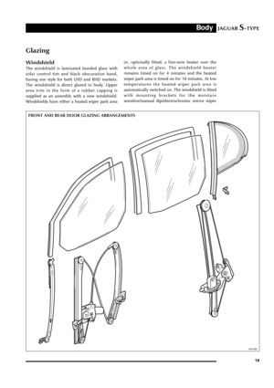 24
24 25
25 26
26 27
27 28
28 29
29 30
30 31
31 32
32 33
33 34
34 35
35 36
36 37
37 38
38 39
39 40
40 41
41 42
42 43
43 44
44 45
45 46
46 47
47 48
48 49
49 50
50 51
51 52
52 53
53 54
54 55
55 56
56 57
57 58
58 59
59 60
60 61
61 62
62 63
63 64
64 65
65 66
66 67
67 68
68 69
69 70
70 71
71 72
72 73
73 74
74 75
75 76
76 77
77 78
78 79
79 80
80 81
81 82
82 83
83 84
84 85
85 86
86 87
87 88
88 89
89 90
90 91
91 92
92 93
93 94
94 95
95 96
96 97
97 98
98 99
99 100
100 101
101 102
102 103
103 104
104 105
105 106
106 107
107 108
108 109
109 110
110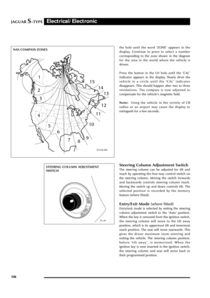 111
111 112
112 113
113 114
114 115
115 116
116 117
117 118
118 119
119 120
120 121
121 122
122 123
123 124
124 125
125 126
126 127
127 128
128 129
129 130
130 131
131 132
132

