Page 49 of 133

JAGUARS-TYPEExhaust System
44
Introduction
D.309.080
The exhaust systems for the V6 and V8 engines
are similar, with minor tuning differences to allow
for the particular flow resistance requirements
and engine characteristics. The complete system is
constructed of 409 stainless steel and consists of
five main components, the two downpipe catalyst
assemblies, the resonator and pipework assembly
and the two mufflers. Brushed stainless steel end
pipes are fitted.
Downpipe Assembly
Different catalysts are fitted to the two engines:
¥ the V8 engine has two 44in
3bricks in each
downpipe assembly, each with 470 cells per
square inch
¥ the V6 engine has two 44in
3bricks in each
downpipe assembly, the front brick having
350 cells and the rear brick 470 cells per
square inch.Resonator Assembly
The resonator assembly is common to both
engines.
Rear Mufflers
The internal parts of the rear mufflers are different
between the two engines and are designed to
produce different quality sounds.
Support and Couplings
The downpipe catalyst assemblies mate to the
exhaust manifold via a two bolt self sealing flange.
The resonator assembly connects to the
downpipes and rear mufflers by Torca clamps.
The system is supported by two isolator rubbers
between the resonator boxes and the rear
subframe and two isolators at the tailpipe end of
the mufflers.
EXHAUST SYSTEM
D.309.080
Down Pipe Catalysts
Resonators
Mufflers
Page 50 of 133

JAGUARS-TYPETransmission
45
Introduction
The automatic and manual transmission units are
described in the ÔS-TYPE Sports Sedan Powertrain
IntroductionÕ Technical Guide.
J-Gate
The J-gate assembly is mounted on the
transmission tunnel by four bolts and has a
similar operating mechanism to the XJ/XK Series
vehicles. The selector gate positions are, P-R-N-D
on one side of the ÔJÕ and manual gear positions
4-3-2 on the other side. Movement of the gear
selector lever up and down these positions is
transmitted mechanically to a cable assembly
which then rotates the digital range switch on the
side of the automatic transmission housing (see
ÔS-TYPE Powertrain IntroductionÕ Technical
Guide). Movement across the gate between D and
4 operates an electrical switch (without cable
movement).
In the P position with the ignition off, the gear
selector lever is locked by a solenoid plunger
which inhibits a lock plate fixed to the selector
mechanism. When the ignition is switched on,pressing the brake pedal energises the solenoid
and releases the lock plate, allowing the selector
lever to be moved from the P position.
For NAS markets only, the J-gate slider actuator is
linked to the ignition switch barrel to provide a
mechanical interlock. The interlock lever and
cable are driven by the J-gate slider to operate a
locking plunger in the ignition barrel. If the gear
selector lever is in any position other than P, the
ignition key cannot be removed. Note when
servicing, that the interlock cable adjustment is
critical and the JTIS service instructions must be
followed. Where the interlock function is not
fitted, the interlock lever is retained without the
operating cable.
D.307.324
J-GATE
Ignition Switch
Interlock Cable
(NAS markets only)
Interlock Lever
(NAS markets only)
D.307.324
Page 51 of 133

JAGUARS-TYPEChassis
46
Introduction
The Jaguar S-TYPE has an all-new suspension,
designed with traditional Jaguar refinement but
with an added sporty feel for the driver. Both
front and rear suspensions have double wishbone
construction with the front having a high balljoint.
JaguarÕs Computer Active Technology Suspension
(CATS), is offered as an optional fit to further
enhance the vehicle ride and handling quality.
The suspension arrangement offers a standard set-
up for most markets. The front and rear control
arms are set at angles to counteract dive when
braking and squat when accelerating, giving a
stable platform under most conditions. It is vitally
J.204.369
FRONT SUSPENSION
J.204.369
Number 1
Cross Member
Number 2
Cross Memberimportant that before removing either of the front
cross members or the rear axle cross members,
the vehicle body and the component being
removed are marked to ensure correct
realignment during assembly. The Jaguar S-TYPE
body-in-white fixings have a greater clearance
than previous Jaguar cars so require this extra
special care with alignment on re-assembly.
Vibration and ride and handling concerns may
arise if alignment is not maintained.
Page 52 of 133

JAGUARS-TYPEChassis
47
Front Suspension
The independent front wheel suspension is a
double wishbone axle arrangement with
aluminium control arms. The two arms are of
different lengths, which minimises the changes in
track and camber. Inclination of the upper control
arm axis provides anti-dive front suspension
action. There are two front cross members,
known as Number 1 and Number 2.
Number 1, the forward cross member, is a steel
fabrication, non-isolated, which locates the lower
control arm front mounting, the anti-roll bar and
the cooling module.
The rear cross member, Number 2, is an
aluminium casting, non-isolated and it locates the
lower control arm rear mounting, the power
steering rack and the engine hydro-mounts.
WARNING: No attempt must be made to
weld or repair the aluminium cross
member. If it is damaged, a new one must
be installed.
Lower Control Arm
The lower control arm is an aluminium forging
and has locations for the damper and the anti-roll
bar drop link. It is mounted with one hydro-bush,
the front lower bush, and one rubber bush, both
serviceable. This is the first time that a hydraulic
bush has been fitted to a Jaguar wishbone. The
hydro-bush is tuned for refinement and helps to
J.204.402
reduce brake vibration.
Service adjustments for caster and camber can be
made to the lower control arm geometry with the
addition of cam bolts (not supplied with the
vehicle).
LOWER CONTROL ARM
J.204.402
Lower
Control Arm
Anti-roll BarAnti-roll Bar
Drop Link
Page 53 of 133
JAGUARS-TYPE
D.204.400
Chassis
48
D.204.440
VERTICAL FRONT KNUCKLE UPPER CONTROL ARM
D.204.440
D.204.400
Upper Control Arm
The upper control arm is also an aluminium
forging, mounted with two rubber bushes and has
an integral, non-serviceable ball joint.
Vertical Front Knuckle
The vertical front knuckle is an aluminium casting
with integral steering arm, installed between the
upper and lower control arms. The lower ball joint
is serviceable and is a press fit. The knuckle
locates the upper balljoint, riveted disk shield and
brake calliper and wheel bearing/hub. The wheel
bearing is a new type and contains the integral
ABS rotor and sensor. The bearing is not
serviceable and must be replaced as a complete
unit. A service kit is available for the ABS sensor.
Vertical Front Knuckle
Disc Shield
Wheel
Bearing/Hub
Page 54 of 133

JAGUARS-TYPEChassis
49
Rear Suspension
The rear suspension is a double wishbone
arrangement with aluminium control arms. The
rear crossbeam is steel fabricated and isolated to
the body with four bushes. The crossbeam locates
the upper and lower control arms and the anti-
roll bar.
Control arms are aluminium castings and heavily
inclined in plan view. The lower control arm
locates the damper and anti-roll bar drop link.
The damper fixing is tapped into the aluminium
casting.
The upper control arm has one cross axis bush
and one rubber bush. It contains an integral
balljoint.
The rear knuckle is an aluminium casting and has
a press fit cartridge bearing.
The independent rear suspension upper and
lower front bushes are conventional rubber
bonded bushes. The upper and lower rear bushes
contain no rubber and are essentially pressed in
ÔroseÕ bearings for superior suspension geometry
control. These are common components between
all vehicle variants and are a similar concept to
D.204.370
D.204.441
REAR SUSPENSION
D.204.370
REAR KNUCKLE
D.204.441
Rear Knuckle
Disc Shield
Wheel
Bearing/Hub
Page 55 of 133

JAGUARS-TYPEChassis
50
D.204.399
FRONT SPRING AND DAMPER
D.204.399
Wheel Alignment
Camber caster and toe are adjustable on the front
suspension only. Toe is the only adjustment on the
rear suspension. Camber and caster are adjusted
by means of eccentric cams on the lower control
arm mounting bolts. The front toe is adjusted by
use of the front tie rod. The rear toe is adjusted by
the use of toe link assemblies connecting the
knuckles to the rear sub-frame.
Anti-roll Bars
There are two types of front anti-roll bars, one for
all V6 and base V8 engined vehicles and one for
V8 sport. There are two types of rear anti-roll
bars, one for all V6 and base V8 engined vehicles
and one for V8 sport.
All anti-roll bars are similar to current saloon
except that the front bushes have moulded insert
for tuning.
Springs and Dampers
There are numerous variants to suit both
ÔstandardÕ and ÔsportÕ derivatives of the V6 and V8
engined vehicles. Both front and rear springs and
dampers are similar to current sports vehicles.
With a strut type assembly, integrated top mount
and two-position lower spring pan. The front and
rear co-axial strut and spring assemblies are
installed between the lower control arms and the
vehicle body.
Sports dampers are CATS only, as XK series.
The CATS suspension is similar to the system
introduced on the XK8. It is a two-stage adaptive
damping ride control. The control module is
located in the rear left-hand corner of the spare
wheel well. Three accelerometers are fitted. The
front vertical and lateral accelerometers are
mounted as an assembly to the vapour
management valve bracket. The lateral
D.204.401
the A-frame bush on current sports and saloon
vehicles. The bushes are not bonded in place but
require a special lubricant when assembling. Care
must be taken to ensure that the replacement
bushes are pushed fully home, the angular
orientation of the bushes is important and it is
essential to mark the position of the subframe
before removing from the vehicle or else driveline
alignment will be lost.
REAR SPRING AND DAMPER
D.204.401
Page 56 of 133
. The rear vertical
accelerometer is fixed to the rear electronic
control module (RECM) bracket on the rear righ")
JAGUARS-TYPEChassis
51 accelerometer is used for Dynamic Stability
control (yaw control). The rear vertical
accelerometer is fixed to the rear electronic
control module (RECM) bracket on the rear right-
hand side of the luggage compartment between
the rear wheel arch and the rear lamp pack.
Suspension Alignment
A special tool has been designed to enable correct
alignment of the suspension to the body.
Connected to a personal computer, a transducer
with a wire measuring device is fitted to a plate
attached to the Number 2 cross member.
Alignment pins are fitted to the body front and
rear to the left-hand side chassis rail and to the
rear suspension beam. Measurements are taken
from one point on the Number 2 beam. Then the
transducer is transferred to the other point on the
beam and a second set of measurements taken.
The PC then calculates if there is any
misalignment and by how much, and displays the
information on the screen. The beam(s) are then
adjusted to bring the alignment back within limits
and a further series of measurements are taken.
This process is repeated until the alignment is
correct and the beams are then tightened. A
print-out of the measurements is to be attached to
the job card as a permanent record of alignment.
Note that camber, caster and toe may be required
if any of the beams have been adjusted.
 1
1 2
2 3
3 4
4 5
5 6
6 7
7 8
8 9
9 10
10 11
11 12
12 13
13 14
14 15
15 16
16 17
17 18
18 19
19 20
20 21
21 22
22 23
23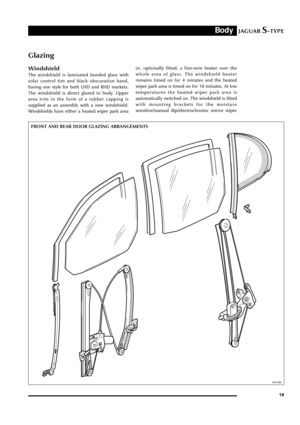 24
24 25
25 26
26 27
27 28
28 29
29 30
30 31
31 32
32 33
33 34
34 35
35 36
36 37
37 38
38 39
39 40
40 41
41 42
42 43
43 44
44 45
45 46
46 47
47 48
48 49
49 50
50 51
51 52
52 53
53 54
54 55
55 56
56 57
57 58
58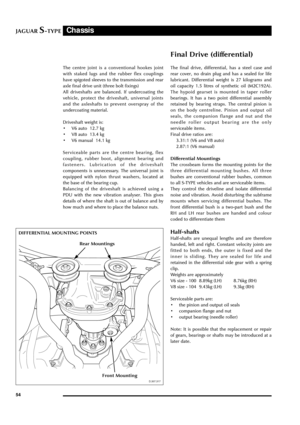 59
59 60
60 61
61 62
62 63
63 64
64 65
65 66
66 67
67 68
68 69
69 70
70 71
71 72
72 73
73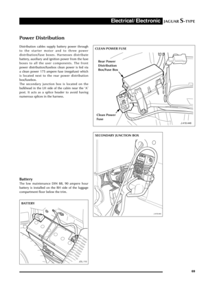 74
74 75
75 76
76 77
77 78
78 79
79 80
80 81
81 82
82 83
83 84
84 85
85 86
86 87
87 88
88 89
89 90
90 91
91 92
92 93
93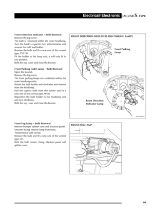 94
94 95
95 96
96 97
97 98
98 99
99 100
100 101
101 102
102 103
103 104
104 105
105 106
106 107
107 108
108 109
109 110
110 111
111 112
112 113
113 114
114 115
115 116
116 117
117 118
118 119
119 120
120 121
121 122
122 123
123 124
124 125
125 126
126 127
127 128
128 129
129 130
130 131
131 132
132