Page 73 of 133

heated front screen.
With the engine running, due to the high current
draw, press to switch on the heated wiper park to
def")
JAGUARS-TYPEClimate Control
68Heated wiper park or (where optionally fitted)
heated front screen.
With the engine running, due to the high current
draw, press to switch on the heated wiper park to
defrost the wiper park area, or where fitted, press
to switch on the heated front screen for rapid
defrost/demist.
Heated wiper park automatically operates in cold
weather, and may stay on continuously. It is
automatically switched on when ÔDEFROSTÕ is
selected. If manually selected, the heated wiper
park will automatically switch off after 10
minutes.
Heated front screen is automatically switched on
when ÔDEFROSTÕ is selected. It will automatically
switch off after 4 minutes. The heaters will switch
off, or not operate, if low battery voltage is
detected.
Heated Rear Screen
With the engine running due to the high current
draw, press to switch on the heated rear screen
for rapid defrost/demist. The rear screen heater
will be automatically switched off after 10
minutes.
In cold conditions, the heated rear screen
operates automatically. Selecting ÔDEFROSTÕ will
also turn the heated rear screen ON. The heaters
will switch off, or not operate, if low battery
voltage is detected.
Air Distribution
Air distribution is automatically controlled when
ÔAUTOÕ is selected. Manual control can be
achieved using the air distribution buttons.
Heat at Rest Feature (V8 engine vehicles
only)
Interior heating may be continued after the
engine has been switched off by turning the
ignition to position ÔIIÕ. The climate control system
will continue to provide heat to the vehicle
interior until the engine cools down. Excessive use
will cause a low battery voltage, which may
prevent the vehicle from being started.
Voice Activated Control
Some functions of the climate control system can
be operated with the Voice Activation System
(when fitted).
A full operating description is given in the Voice
Activation Handbook included with the vehicle
literature pack.
Page 74 of 133
JAGUARS-TYPEElectrical/Electronic
69
Power Distribution
Distribution cables supply battery power through
to the starter motor and to three power
distribution/fuse boxes. Harnesses distribute
battery, auxiliary and ignition power from the fuse
boxes to all the user components. The front
power distribution/fusebox clean power is fed via
a clean power 175 ampere fuse (megafuse) which
is located next to the rear power distribution
box/fusebox.
The secondary junction box is located on the
bulkhead in the LH side of the cabin near the ÔAÕ
post. It acts as a splice header to avoid having
numerous splices in the harness.
J.418.446
CLEAN POWER FUSE
J.418.444
SECONDARY JUNCTION BOX
JOL.110
BATTERY
Rear Power
Distribution
Box/Fuse Box
Clean Power
Fuse
Battery
The low maintenance DIN 88, 90 ampere hour
battery is installed on the RH side of the luggage
compartment floor below the trim.
Page 75 of 133
JAGUARS-TYPEElectrical/Electronic
70
BATTERY AND FUSE BOX POWER DISTRIBUTION
1. Front power distribution box (fusebox)
2. Primary junction box (fusebox)
3. Power stud
4. Battery Positive cable
5. Rear power distribution box (fusebox)
6. Battery Negative cable
7. Battery8. Clean power fuse (Megafuse)
9. Clean power feed
10. Secondary junction box.
11. Starter motor
12. Alternator/starter positive cable
13. Alternator
Power Distribution Cables
Heavy duty power distribution cables connect the
battery to the body and to the engine starter and
the vehicle fuse boxes. The distribution cable from
the clean power fuse to the front fusebox is
routed on the LH side of the vehicle and along
part of the main body wiring harness.
Harnesses
The vehicle harnesses plug directly into
components or component flying leads using
locking connectors. The main harness layout is
shown in the illustration on the following page.
12
10
4
1113
3
9
8
65
7
12
Page 76 of 133
JAGUARS-TYPE
J.418.426
Electrical/Electronic
71 HARNESS LAYOUT
Main Body Harness
Front Harness
Roof Harness
Engine Management
Harness
Instrument Pack/Fascia
Harness
Page 77 of 133

JAGUARS-TYPEElectrical/Electronic
72
Module Communications Network
ISO9141 DIAGNOSTICS LINK
Powertrain
Control Module
ABS/TC
Control Module
Dynamic Stability
Control Module
Restraint
Control Module
Adaptive Damping
Control Module
Park Aid
Control Module
Data Link
Connector
PCM Flash Programming Link
Serial Data Link The multiplexed electrical architecture is used for
the exchange of information between control
modules, the instrument pack and the data link
connector.
Multiplexing allows more than one piece of
information to be carried along a wire. In this
way, the electronic control modules can
communicate with each other quickly and share
information. With multiplexing, just two
intertwined wires carry information to any control
module on the network. On the SCP system
hundreds of messages a second can be
transmitted; the maximum waiting time is only a
few hundred milliseconds. An additional benefit is
that the modules ÔsleepÕ when not in use,
reducing battery drain.Principles of Operation
The vehicle has two module communication
networks. The first is the Standard Corporate
Protocol (SCP - J1850 SAE standard)), which is an
unshielded twisted pair cable: data bus plus and
data bus minus. The second is the International
Standard Organization (ISO) 9141 communication
network, which is a single wire network. Both
networks can be connected to the PDU tester by
one connector: the data link connector. The data
link connector is located under the instrument
panel, between the steering column and the audio
unit.
The ISO 9141 communications network does not
permit inter-module communications. When the
PDU tester communicates to modules on the ISO
9141 communication network , the PDU must ask
for all information; the modules initiate
communications.
Page 78 of 133
JAGUARS-TYPEElectrical/Electronic
73 STANDARD CORPORATE PROTOCOL (SCP) NETWORK
Powertrain
Control Module
Vehicle Emergency
Control Module
Throttle Actuator
Control Module
General Electronic
Control Module
Rear Electronic
Control Module
Navigation
Control Module
Adaptive Damping
Control Module
Voice Activation
Control Module
Air Conditioning
Control Module
Data Link
Connector
Instrument
Pack
Audio Unit
Steering Column
Lock Module
Dynamic Stability
Control Module
Secondary
Junction BoxDriver Seat
Control Module
Driver Door
Control Module
ABS/TC
Control Module
Page 79 of 133

JAGUARS-TYPEElectrical/Electronic
74The SCP communication network will remain
operational even with severing of one of the bus
wires. Communications will also continue if one
of the bus wires is shorted to ground or battery
positive voltage (B+), or if some , but not all,
termination resistors are lost.
Unlike the SCP communication network, the
ISO 9141 communication network will not
function if the wire is shorted to ground or battery
positive voltage (B+). Also, if one of the modules
on the ISO 9141 network loses power or shorts
internally, communication to that module will fail.
Control Modules
The vehicle control module functions are
described briefly below (for further information
refer to the relevant sections throughout the
Guide).
Anti Lock Brake/Traction Control and
Dynamic Stability Control, Control Modules
The anti-lock brake control module is connected
to the SCP communication network. The module
comes in two forms. The first type is the standard
equipped anti-lock brake system (ABS) with
traction control (TC). It controls the brake
pressure to the four wheels to keep the vehicle
under control while braking.
The second type of ABS is optional and is called
dynamic stability control (DSC). This control
module adds yaw sensors to the package to help
in sensing a loss of vehicle control.
Audio Control Unit
The audio control unit is connected to the SCP
communication network and also to the audio
control protocol (ACP) communication network.
The audio control unit communicates with the
compact disc and the cellular phone transceiver.
Driver Door Control Module (DDCM)
DDCM is connected to the SCP communication
network. The module controls many functions
including power windows, driver mirror, power
locks, and keyless remote entry.Driver Seat Control Module (DSCM)
The DSCM is connected to the SCP
communication network. The DSCM is located
under the driver seat and controls the seat
positions. The module also communicates with the
DDCM to control the driver seat memory
functions.
Control Module Locations
Key to illustration on following page:
1.Anti-lock brake system/Traction control
system or Dynamic stability control
(ABS/TCCM or DSCCM)
(non-handed)
2.Throttle actuator control module (TACM)
(non-handed)
3.Powertrain control module (PCM) (handed)
4.Air conditioning control module (A/CCM)
(non-handed)
5.Restraint control module (RCM) (non-handed)
6.Sliding roof control module (SRCM)
(non-handed)
7.Passenger seat heater control module
(PSHCM) (non-handed)
8.Rear electronic control module (RECM)
(non-handed)
9.Vehicle information control module (VICM)
(Japan only)
10.Adaptive damping control module (ADCM)
(non-handed)
11.Parking aid control module (PACM)
(non-handed)
12.Navigation control module (NCM)
(non-handed)
13.Vehicle emergency control module (VECM)
(non-handed)
14.Voice-activated control module (VACM)
(non-handed)
15.Cellular telephone control module (CTCM)
(non-handed)
16.Driver seat heater control module (DSHCM)
(non-handed)
17.Driver seat control module (DSCM) (handed)
18.Driver door control module (DDCM)
(handed)
19.Instrument pack (handed)
20.General electronics control module (GECM)
(non-handed)
21.Steering column lock module (SCLM) (handed)
Page 80 of 133
JAGUARS-TYPEElectrical/Electronic
75
J.418.424
1
12
1110
9
8
7
6
5
4
3
2
16
13
14
15
20
19
18
17
21 CONTROL MODULES LOCATIONS (LHD)
 1
1 2
2 3
3 4
4 5
5 6
6 7
7 8
8 9
9 10
10 11
11 12
12 13
13 14
14 15
15 16
16 17
17 18
18 19
19 20
20 21
21 22
22 23
23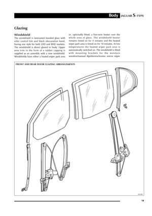 24
24 25
25 26
26 27
27 28
28 29
29 30
30 31
31 32
32 33
33 34
34 35
35 36
36 37
37 38
38 39
39 40
40 41
41 42
42 43
43 44
44 45
45 46
46 47
47 48
48 49
49 50
50 51
51 52
52 53
53 54
54 55
55 56
56 57
57 58
58 59
59 60
60 61
61 62
62 63
63 64
64 65
65 66
66 67
67 68
68 69
69 70
70 71
71 72
72 73
73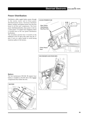 74
74 75
75 76
76 77
77 78
78 79
79 80
80 81
81 82
82 83
83 84
84 85
85 86
86 87
87 88
88 89
89 90
90 91
91 92
92 93
93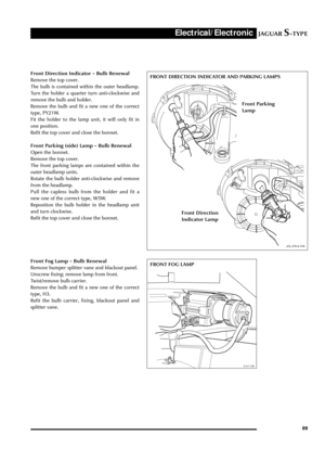 94
94 95
95 96
96 97
97 98
98 99
99 100
100 101
101 102
102 103
103 104
104 105
105 106
106 107
107 108
108 109
109 110
110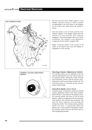 111
111 112
112 113
113 114
114 115
115 116
116 117
117 118
118 119
119 120
120 121
121 122
122 123
123 124
124 125
125 126
126 127
127 128
128 129
129 130
130 131
131 132
132

2. Primary junction box (fusebox)
3. Power stud
4. Battery Positive cable")

 NETWORK
Powertrain
Control Module
Vehicle Emergency
Control Module
Throttle Actuator
Control Module
General Electronic
Control Mo")
")