Page 57 of 133
JAGUARS-TYPE
Wheels and Tyres
Chassis
52
Wheels
All wheels are alloy except for the space saver
wheel which is steel. The space saver wheel is not
available for USA, Canada or Mexico.
There are three wheel styles:
¥ 7 x 16 Classic
¥ 7.5 x 16 Dynamic
¥ 7.5 x 17 Sport (option)
Each wheel has five exposed wheel nuts which are
smaller than current cars at 19mm A/F
Locking wheel nut policy is the same as current
sedan vehicles.
Ty r e s
Two sizes - three types:
¥ 225/55R16
All season (NAS markets)
Summer (European/Rest of World)
Winter (accessory)
¥ 235/50R17
Summer (European/Rest of World)
Winter (accessory)
Tyres for the European and Rest of World markets
Summer/Winter, are Pirelli.
The all season tyres are Bridgestone and for the
NAS markets only.
Tyre pressures are:
¥ 26/28 psi comfort
¥ 32/34 high speed or fully laden.
D.501.1477
S-TYPE WHEELS
D.501.1477,1478 & 1479
Classic
Sport
Dynamic
D.501.1478
D.501.1479
Page 58 of 133

JAGUARS-TYPEChassis
53
Driveline
Introduction
The driveline is a standard type with the engine
position at the front and driven rear axle. This will
be the first time that Jaguar has used in-plant
driveline balancing to improve noise, vibration
and handling. The driveline is finely balanced at
the rear driveshaft joint. The centre bearing is
laser aligned during initial factory build.
The alloy rear engine mountings have two
variants, one for automatic transmission and one
for manual transmission. They are both
serviceable items. The V6 auto is the same as the
V8 but rotated in plan by 180 degrees. The rubber
mountings are carry over concept from the
current XJ and XK Series vehicles but are not
D.307.322
DRIVELINE ARRANGEMENTinterchangeable with them. Both automatic
transmission rubber mountings are common but
with a softer unique mount for the manual V6
transmission.
In service if they are replaced, ensure that there
are buffer gaps and that they are approximately
equal. Neither will be contaminated by lubricant
or automatic transmission fluid.
Driveshaft
The S-TYPE has a two-piece welded steel tube
driveshaft with a splined centre slip joint and
locking collar, the whole being aligned with the
body centreline. The driveshaft has rubber flex
couplings and a rubber, body-mounted, centre
bearing. For safety, the front tube is collapsible.
Page 59 of 133

JAGUARS-TYPEChassis
54The centre joint is a conventional hookes joint
with staked lugs and the rubber flex couplings
have spigoted sleeves to the transmission and rear
axle final drive unit (three bolt fixings)
All driveshafts are balanced. If undercoating the
vehicle, protect the driveshaft, universal joints
and the axleshafts to prevent overspray of the
undercoating material.
Driveshaft weight is:
¥ V6 auto 12.7 kg
¥ V8 auto 13.4 kg
¥ V6 manual 14.1 kg
Serviceable parts are the centre bearing, flex
coupling, rubber boot, alignment bearing and
fasteners. Lubrication of the driveshaft
components is unnecessary. The universal joint is
equipped with nylon thrust washers, located at
the base of the bearing cup.
Balancing of the driveshaft is achieved using a
PDU with the new vibration analyser. This gives
details of where the shaft is out of balance and by
how much and where to place the balance nuts.
Final Drive (differential)
The final drive, differential, has a steel case and
rear cover, no drain plug and has a sealed for life
lubricant. Differential weight is 27 kilograms and
oil capacity 1.5 litres of synthetic oil (M2C192A).
The hypoid gearset is mounted in taper roller
bearings. It has a two point differential assembly
retained by bearing straps. The central pinion is
on the body centreline. Pinion and output oil
seals, the companion flange and nut and the
needle roller output bearing are the only
serviceable items.
Final drive ratios are:
3.31:1 (V6 and V8 auto)
2.87:1 (V6 manual)
Differential Mountings
The crossbeam forms the mounting points for the
three differential mounting bushes. All three
bushes are conventional rubber bushes, common
to all S-TYPE vehicles and are serviceable items.
They control the driveline and isolate differential
noise and vibration. Avoid disturbing the subframe
mounts when servicing differential bushes. The
front differential bush is a two-part bush and the
RH and LH rear bushes are handed and colour
coded to differentiate them
Half-shafts
Half-shafts are unequal lengths and are therefore
handed, left and right. Constant velocity joints are
fitted to both ends, the outer is fixed and the
inner is sliding. They are sealed for life and
retained in the differential side gear with a spring
clip.
Weights are approximately
V6 size - 100 8.89kg (LH) 8.76kg (RH)
V8 size - 104 9.43kg (LH) 9.3kg (RH)
Serviceable parts are:
¥ the pinion and output oil seals
¥ companion flange and nut
¥ output bearing (needle roller)
Note: It is possible that the replacement or repair
of gears, bearings or shafts may be introduced at a
later date.
D.307.317
DIFFERENTIAL MOUNTING POINTS
D.307.317
Front Mounting
Rear Mountings
Page 60 of 133
 contains the integral so")
JAGUARS-TYPEChassis
55
Brakes
Brake Control Module
Brakes are controlled with a Teeves Mk 20E brake
modulator.
The anti-lock brake/traction control, control
module (ABS/TCCM) contains the integral software
for ABS and traction control, similar to current XJ
and XK Series vehicles. It is supplied as a 10 valve,
4-channel module and calibration is the same to
all powertrains. It is connected to the SCP bus for
traction control, warnings and vehicle speed.
Dynamic Stability Control
Dynamic stability control (DSC) is a new Jaguar
safety feature, which uses ABS and traction
control to control yaw movements of the vehicle.
Yaw is the rotary motion of the vehicle on its
vertical axis, a force that would cause oversteer or
oversteer or sideslip. The dynamic stability
control module (DSCM) contains the same
software as described but with the addition of IVD
software. The modulator is supplied as a 12 valve,
4-channel module calibrated for base suspension
only. The connectors differ between the two; the
10 valve unit has a 25-way with sliding cam, as
D.206.254
D.206.175
BRAKE CONTROL MODULE
BRAKE SYSTEM LAYOUT
Page 61 of 133
 and
compares it to the dire")
JAGUARS-TYPEChassis
56
D.206.177
current vehicles and the 12 valve unit has a 47-
way connector with lever cam. DSC calculates the
real vehicle motion (forward and gearing) and
compares it to the direction initially chosen by the
driver. A steering rate sensor is located on the
steering column and is used to calculate steering
angle. A yaw rate sensor and lateral accelerometer
are located on a bracket behind the hand brake
lever and are used to calculate the vehicle under
or over steer and any side slip.
As soon as DSC recognises that the driver is not
reacting sufficiently to compensate a deviation,
DSC intervenes by applying brake force to each of
the four wheels individually to control yaw
Front Wheel Sensor
The front wheel active ABS speed sensors are
incorporated into the wheel bearings, connected
via a flying lead routed along the brake hose.
Rear Wheel Sensor
The rear sensors are mounted on the hub carrier
and connected by a flying lead routed along the
control arm. None of the sensors are adjustable.
Wheel speed sensors are new active sensors,
which are more sensitive at lower speeds that the
current saloon and sports wheel speed sensors.
Front and Rear Callipers
Front callipers are twin piston aluminium
construction. The ventilated disc sizes are 300 mm
x 32 mm. The rear brakes have cast iron callipers.
This is because of the hand brake operation using
the rear callipers. The ventilated disc sizes are 288
mm x 20 mm. Each rear calliper has a ball and
ramp park brake mechanism, operating on the
main calliper pads.
D.206.178
D.206.177
FRONT WHEEL SENSOR
REAR WHEEL SENSOR
D.206.178
Page 62 of 133

JAGUARS-TYPEChassis
57
D.206.176
BRAKE BOOSTER Brake Booster
The brake booster is a Lucas unit mounted on the
engine bay bulkhead with a 25.4mm diameter
master cylinder and integral brake fluid reservoir.
NOTE: The reservoir is also a combined
brake/clutch reservoir for manual transmission
vehicles.
Twin vacuum boosters of 8 inch and 9 inch sizes
are fitted.
The DSC booster is different having integral
pressure transducers and solenoids with air
control valves for the booster. The transducers are
located on the brake master cylinder and are used
for pressure feedback, brake application and fail
safe operation. The booster is used to supply
brake pressure without driver input.
ABS operation is no different to current Jaguar
vehicles.
Parking Brake
The parking brake lever is mounted on the RH
side of the centre console for all models, with
conventional button operation as current XJ
sedan. It is a self-adjusting system operating on
the rear brake callipers. All models have a leather
grip.
D.206.158
PARKING BRAKE
Page 63 of 133

JAGUARS-TYPEChassis
58
Power Assisted Steering
Introduction
The Jaguar S-TYPE has a variable assist rack and
pinion steering gear and variable rack ratio. The
variable steering rack ratio reduces the number of
turns from lock to lock (2.8) to enhance parking
manoeuvrability whilst maintaining the on-centre
steering precision required at high speed. Full
power assistance is provided for parking. Steering
assistance decreases smoothly at a calibrated rate
to raise driver steering efforts as vehicle speed
increases.
Servicing
There are no carry over parts from XK or XJ Series
vehicles.
The rack is mounted to the rear of cross member
Number 2. The PAS pump is belt driven. A PAS
cooler matrix is located within the radiator
package.
Low PAS pump speeds problems are prevented by
increasing engine speed. A power steering
pressure (PSP) switch senses the demand on the
pump at low engine speeds and increases the
speed to a pre-set minimum.
Hose connections to the pump and the steering
gear are quickfit connectors. The quick connect
tube must be pushed into the existing tube nut
port, along the centreline. The assembly is
complete when the tube end bottoms out in the
port with an audible click/snap. Correct assembly
should be verified by pulling the quickfit tube end.
Servicing of the PAS line involves removal of the
quickfit nut. Replacement PAS lines are supplied
complete with quickfit nut and sealing washer. If
the joint is disturbed it is compulsory to replace
the PTFE sealing ring otherwise leaks are
inevitable. Replacement sealing washers may be
installed with the use of Service tool
D90P-3517-A.
Care must be taken when removing the quickfit
nut from the V6 engine pump as the pulley is
PHENOLIC and is susceptible to damage. The V8
pump installation provides a short jumper tube
from the pump to improve accessibility to the
high-pressure hose connection. The PAS pulley
D.211.247
PA S R AC K
D.211.258
POWER STEERING PRESSURE SWITCH
Page 64 of 133
 clamps. Pinion hydraulic
connections")
JAGUARS-TYPEChassis
59
D.211.248
FRONT STEERING ARM requires a Service tool to assist removal. Low-
pressure hose connections are made using
Constant Tension (CT) clamps. Pinion hydraulic
connections are orientated with the bottom
connector low pressure with the longer nut, as
current vehicles.
The PAS fluid is for PAS only; it is not to be used
for transmissions. After manual filling, the system
must be bled using a vacuum pump to remove all
the air from the system to prevent system noises.
Fluid level is checked through a sight window on
the reservoir.
Components replaceable are complete pump,
steering rack, reservoir or hose assembly.
A non-serviceable 10-micron filter is located
within the reservoir to maintain fluid cleanliness
throughout the life of the vehicle. It is essential as
with all Jaguars that the system does not become
contaminated. Cap all ports on disassembly to
prevent contamination ingress. As with current
vehicles, the fluid and reservoir must be renewed
if any major component is replaced i.e. Rack,
pump or cooler.
The road wheels should be set straight ahead and
the steering wheel locked (using service tool
F7LC-3F732-BF) when removal and assembly of
the steering gear or intermediate shaft is required.
This is necessary to prevent damage to the air bag
clock spring within the steering upper column
assembly. The intermediate shaft can only be
assembled to its mating components in one
location. Steering wheel alignment can only be
achieved by adjustment at the tie-rods. A
dimensional check of the steering rack position
may be necessary to verify rack centre.
Steering Column
The steering column assembly is completely new
and uses no parts from previous Jaguar
assemblies:
¥ Construction of the upper column assembly is
based on the use of aluminium extrusions and
castings.
¥ A two shaft lower column assembly is used.
¥ The electronically controlled steering lock, the
steering column lock module (SCLM), is a
physically separate component from the
ignition switch which is fascia mounted.
¥ The dynamic stability control (DSC) steering
wheel position sensor is fitted to the upper
column assembly.
Steering Wheel
The steering wheel consists of a magnesium
armature with a central steel insert. The steering
column and wheel insert are splined with a flat so
that the wheel can only be fitted in one position.
Any misalignment of the steering wheel is
corrected by adjusting the tie rods. The splined
fitting also has a locking taper which requires the
use of a 2 legged puller to remove the wheel.
The steering wheel incorporates the the airbag
module, horn mechanism and the optional cruise
control and audio/phone switches.
 1
1 2
2 3
3 4
4 5
5 6
6 7
7 8
8 9
9 10
10 11
11 12
12 13
13 14
14 15
15 16
16 17
17 18
18 19
19 20
20 21
21 22
22 23
23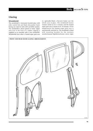 24
24 25
25 26
26 27
27 28
28 29
29 30
30 31
31 32
32 33
33 34
34 35
35 36
36 37
37 38
38 39
39 40
40 41
41 42
42 43
43 44
44 45
45 46
46 47
47 48
48 49
49 50
50 51
51 52
52 53
53 54
54 55
55 56
56 57
57 58
58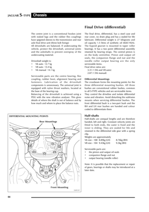 59
59 60
60 61
61 62
62 63
63 64
64 65
65 66
66 67
67 68
68 69
69 70
70 71
71 72
72 73
73 74
74 75
75 76
76 77
77 78
78 79
79 80
80 81
81 82
82 83
83 84
84 85
85 86
86 87
87 88
88 89
89 90
90 91
91 92
92 93
93 94
94 95
95 96
96 97
97 98
98 99
99 100
100 101
101 102
102 103
103 104
104 105
105 106
106 107
107 108
108 109
109 110
110 111
111 112
112 113
113 114
114 115
115 116
116 117
117 118
118 119
119 120
120 121
121 122
122 123
123 124
124 125
125 126
126 127
127 128
128 129
129 130
130 131
131 132
132