Page 68 of 136
A09543
SSTSST
A09541
A09540
Sharp 6 mm
Reamer 14±28
± ENGINE MECHANICALCYLINDER HEAD ASSY (1CD±FTV)
1CD±FTV ENGINE REPAIR MANUAL (RM927E)
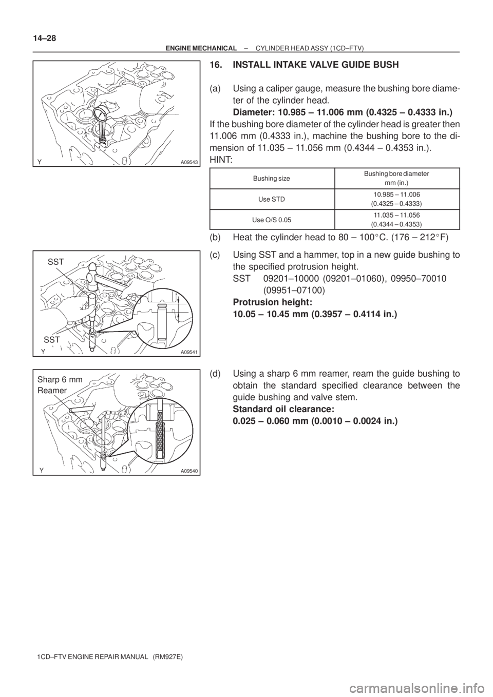
16. INSTALL INTAKE VALVE GUIDE BUSH
(a) Using a caliper gauge, measure the bushing bore diame-
ter of the cylinder head.
Diameter: 10.985 ± 11.006 mm (0.4325 ± 0.4333 in.)
If the bushing bore diameter of the cylinder head is greater then
11.006 mm (0.4333 in.), machine the bushing bore to the di-
mension of 11.035 ± 11.056 mm (0.4344 ± 0.4353 in.).
HINT:
Bushing sizeBushing bore diameter
mm (in.)
Use STD10.985 ± 11.006
(0.4325 ± 0.4333)
Use O/S 0.0511.035 ± 11.056
(0.4344 ± 0.4353)
(b) Heat the cylinder head to 80 ± 100�C. (176 ± 212�F)
(c) Using SST and a hammer, top in a new guide bushing to
the specified protrusion height.
SST 09201±10000 (09201±01060), 09950±70010
(09951±07100)
Protrusion height:
10.05 ± 10.45 mm (0.3957 ± 0.4114 in.)
(d) Using a sharp 6 mm reamer, ream the guide bushing to
obtain the standard specified clearance between the
guide bushing and valve stem.
Standard oil clearance:
0.025 ± 0.060 mm (0.0010 ± 0.0024 in.)
Page 69 of 136
A56676
A56677
SST
A56678
Sharp 6 mm
Reamer
± ENGINE MECHANICALCYLINDER HEAD ASSY (1CD±FTV)
14±29
1CD±FTV ENGINE REPAIR MANUAL (RM927E)
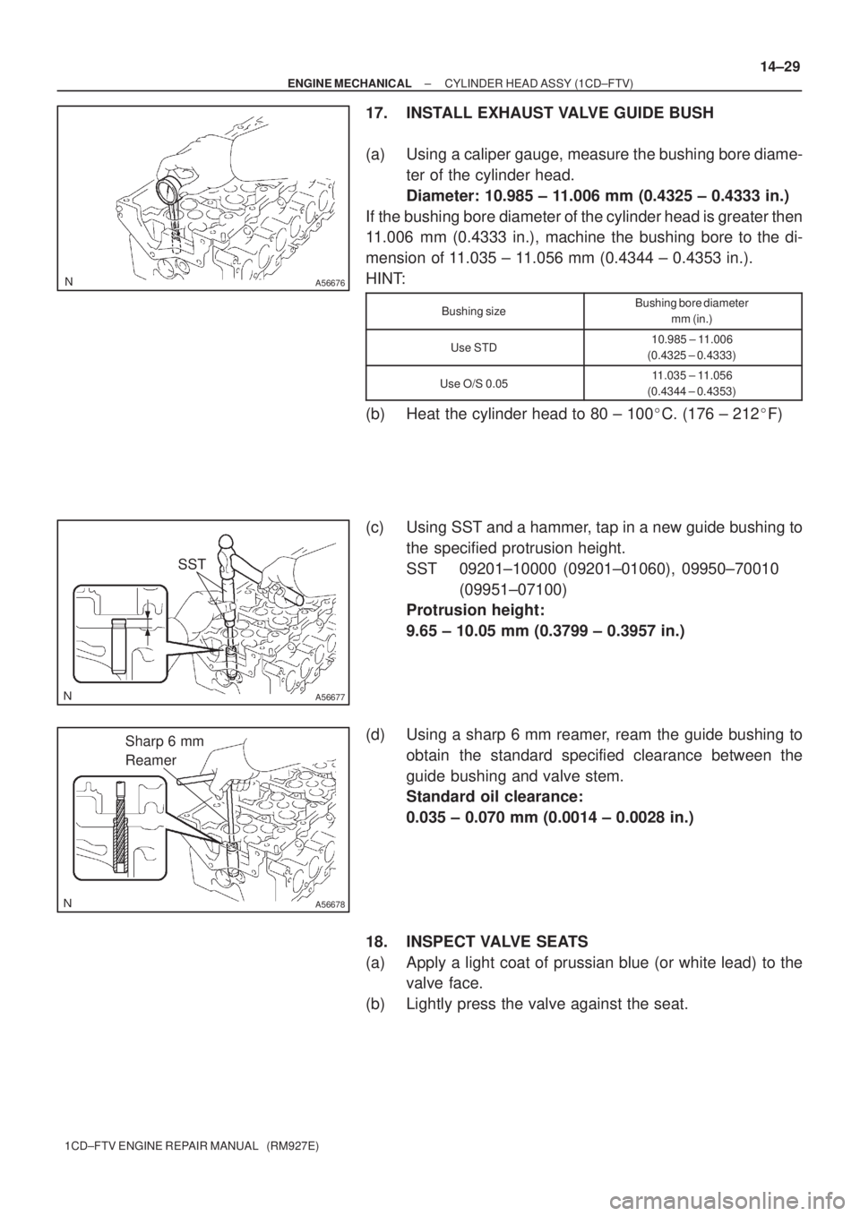
17. INSTALL EXHAUST VALVE GUIDE BUSH
(a) Using a caliper gauge, measure the bushing bore diame-
ter of the cylinder head.
Diameter: 10.985 ± 11.006 mm (0.4325 ± 0.4333 in.)
If the bushing bore diameter of the cylinder head is greater then
11.006 mm (0.4333 in.), machine the bushing bore to the di-
mension of 11.035 ± 11.056 mm (0.4344 ± 0.4353 in.).
HINT:
Bushing sizeBushing bore diameter
mm (in.)
Use STD10.985 ± 11.006
(0.4325 ± 0.4333)
Use O/S 0.0511.035 ± 11.056
(0.4344 ± 0.4353)
(b) Heat the cylinder head to 80 ± 100�C. (176 ± 212�F)
(c) Using SST and a hammer, tap in a new guide bushing to
the specified protrusion height.
SST 09201±10000 (09201±01060), 09950±70010
(09951±07100)
Protrusion height:
9.65 ± 10.05 mm (0.3799 ± 0.3957 in.)
(d) Using a sharp 6 mm reamer, ream the guide bushing to
obtain the standard specified clearance between the
guide bushing and valve stem.
Standard oil clearance:
0.035 ± 0.070 mm (0.0014 ± 0.0028 in.)
18. INSPECT VALVE SEATS
(a) Apply a light coat of prussian blue (or white lead) to the
valve face.
(b) Lightly press the valve against the seat.
Page 71 of 136
45�25�
Z03988
45�
65�
A57106
A56679
EM2196
A09544
± ENGINE MECHANICALCYLINDER HEAD ASSY (1CD±FTV)
14±31
1CD±FTV ENGINE REPAIR MANUAL (RM927E)
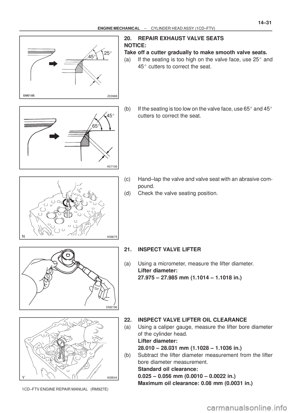
20. REPAIR EXHAUST VALVE SEATS
NOTICE:
Take off a cutter gradually to make smooth valve seats.
(a) If the seating is too high on the valve face, use 25� and
45� cutters to correct the seat.
(b) If the seating is too low on the valve face, use 65� and 45�
cutters to correct the seat.
(c) Hand±lap the valve and valve seat with an abrasive com-
pound.
(d) Check the valve seating position.
21. INSPECT VALVE LIFTER
(a) Using a micrometer, measure the lifter diameter.
Lifter diameter:
27.975 ± 27.985 mm (1.1014 ± 1.1018 in.)
22. INSPECT VALVE LIFTER OIL CLEARANCE
(a) Using a caliper gauge, measure the lifter bore diameter
of the cylinder head.
Lifter diameter:
28.010 ± 28.031 mm (1.1028 ± 1.1036 in.)
(b) Subtract the lifter diameter measurement from the lifter
bore diameter measurement.
Standard oil clearance:
0.025 ± 0.056 mm (0.0010 ± 0.0022 in.)
Maximum oil clearance: 0.08 mm (0.0031 in.)
Page 72 of 136
A09550
A09551
A09552
A09546
Plastigage
A09557
14±32
± ENGINE MECHANICALCYLINDER HEAD ASSY (1CD±FTV)
1CD±FTV ENGINE REPAIR MANUAL (RM927E)
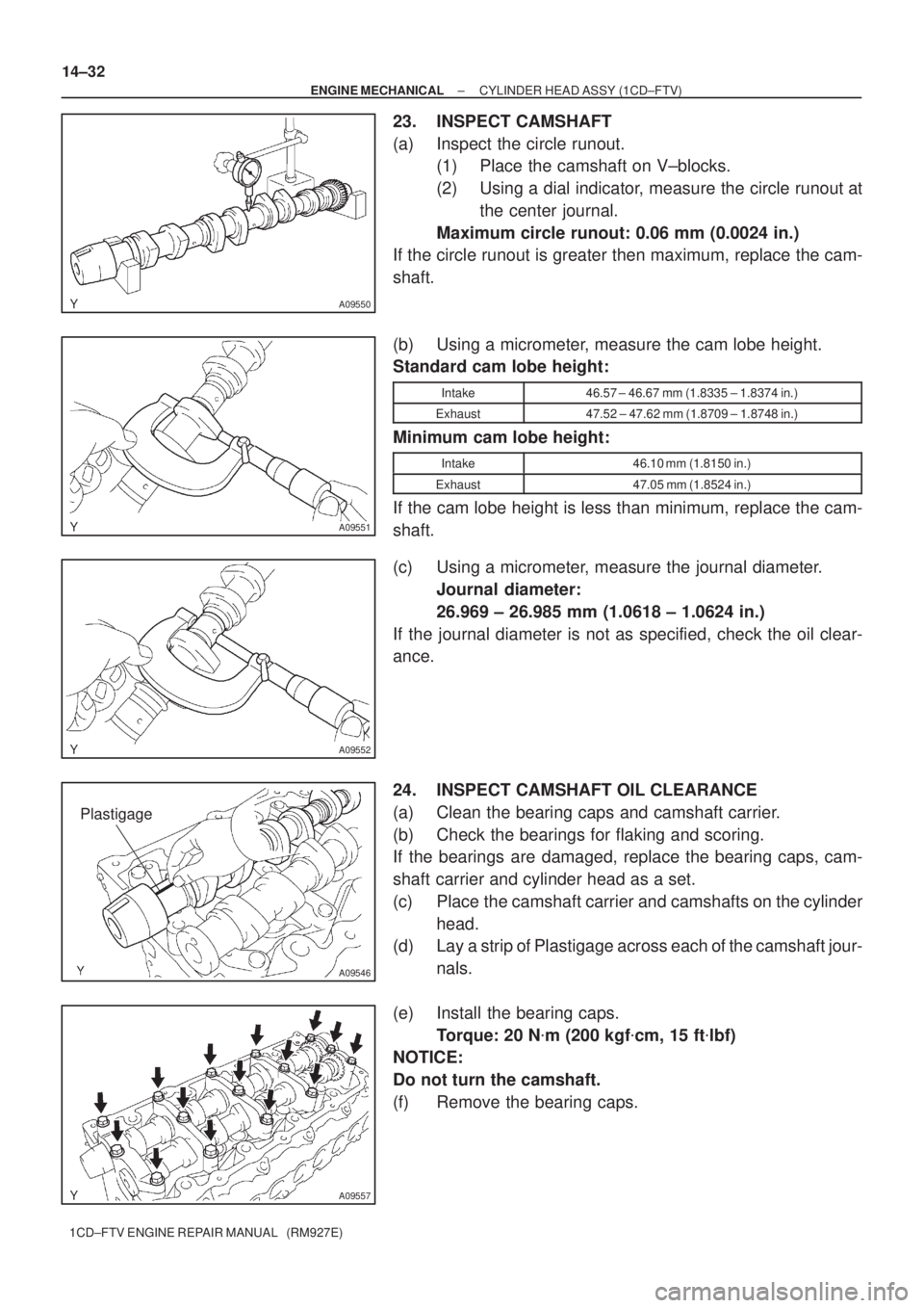
23. INSPECT CAMSHAFT
(a) Inspect the circle runout.
(1) Place the camshaft on V±blocks.
(2) Using a dial indicator, measure the circle runout at
the center journal.
Maximum circle runout: 0.06 mm (0.0024 in.)
If the circle runout is greater then maximum, replace the cam-
shaft.
(b) Using a micrometer, measure the cam lobe height.
Standard cam lobe height:
Intake46.57 ± 46.67 mm (1.8335 ± 1.8374 in.)
Exhaust47.52 ± 47.62 mm (1.8709 ± 1.8748 in.)
Minimum cam lobe height:
Intake46.10 mm (1.8150 in.)
Exhaust47.05 mm (1.8524 in.)
If the cam lobe height is less than minimum, replace the cam-
shaft.
(c) Using a micrometer, measure the journal diameter.
Journal diameter:
26.969 ± 26.985 mm (1.0618 ± 1.0624 in.)
If the journal diameter is not as specified, check the oil clear-
ance.
24. INSPECT CAMSHAFT OIL CLEARANCE
(a) Clean the bearing caps and camshaft carrier.
(b) Check the bearings for flaking and scoring.
If the bearings are damaged, replace the bearing caps, cam-
shaft carrier and cylinder head as a set.
(c) Place the camshaft carrier and camshafts on the cylinder
head.
(d) Lay a strip of Plastigage across each of the camshaft jour-
nals.
(e) Install the bearing caps.
Torque: 20 N�m (200 kgf�cm, 15 ft�lbf)
NOTICE:
Do not turn the camshaft.
(f) Remove the bearing caps.
Page 73 of 136
A09547
A09545
A09548
± ENGINE MECHANICALCYLINDER HEAD ASSY (1CD±FTV)
14±33
1CD±FTV ENGINE REPAIR MANUAL (RM927E)
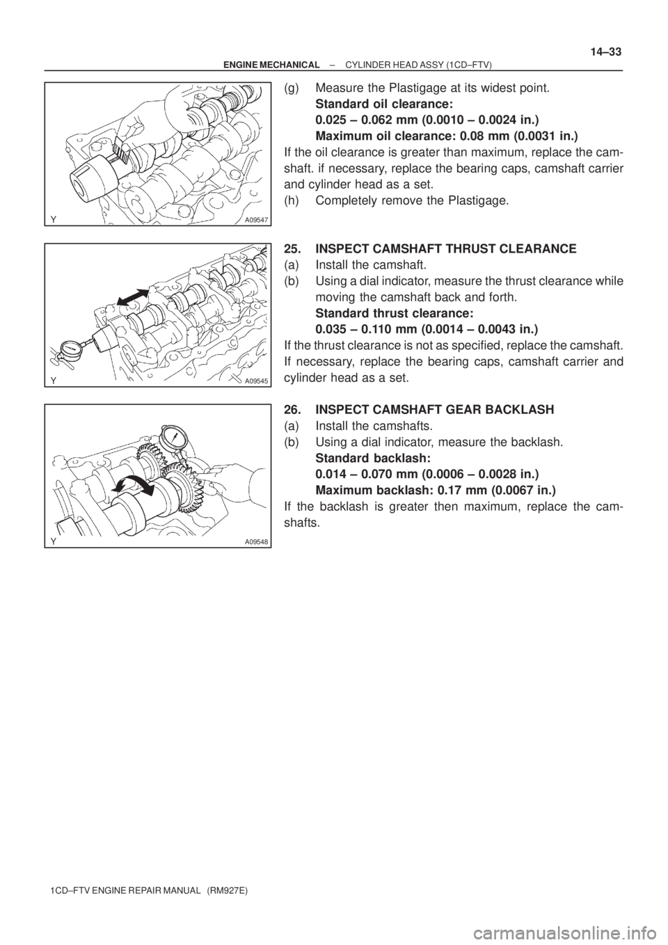
(g) Measure the Plastigage at its widest point.
Standard oil clearance:
0.025 ± 0.062 mm (0.0010 ± 0.0024 in.)
Maximum oil clearance: 0.08 mm (0.0031 in.)
If the oil clearance is greater than maximum, replace the cam-
shaft. if necessary, replace the bearing caps, camshaft carrier
and cylinder head as a set.
(h) Completely remove the Plastigage.
25. INSPECT CAMSHAFT THRUST CLEARANCE
(a) Install the camshaft.
(b) Using a dial indicator, measure the thrust clearance while
moving the camshaft back and forth.
Standard thrust clearance:
0.035 ± 0.110 mm (0.0014 ± 0.0043 in.)
If the thrust clearance is not as specified, replace the camshaft.
If necessary, replace the bearing caps, camshaft carrier and
cylinder head as a set.
26. INSPECT CAMSHAFT GEAR BACKLASH
(a) Install the camshafts.
(b) Using a dial indicator, measure the backlash.
Standard backlash:
0.014 ± 0.070 mm (0.0006 ± 0.0028 in.)
Maximum backlash: 0.17 mm (0.0067 in.)
If the backlash is greater then maximum, replace the cam-
shafts.
Page 77 of 136
A56032
A56684
A62597
SST
A62598
A62599
± ENGINE MECHANICALCYLINDER HEAD ASSY (1CD±FTV)
14±37
1CD±FTV ENGINE REPAIR MANUAL (RM927E)
34. INSTALL VALVE STEM OIL O SEAL OR RING
(a) Apply a light coat of engine oil on the valve stem.
(b) Install a new oil seal on the valve guide bushing.
35. INSTALL INTAKE VALVE
(a) Install the valve, valve spring, and spring retainer.
(b) Using SST, compress the valve spring and place the 2
keepers around the valve stem.
SST 09202±70020 (09202±00010)
(c) Using a plastic±faced hammer and the valve stem (not in
use) tip wound with vinyl tape, lightly tap the valve stem
tip to ensure a proper fit.
NOTICE:
Be careful not to damage the valve stem tip.
36. INSTALL EXHAUST VALVE
(a) Install the valve, valve spring, and spring retainer.
Page 79 of 136
140L6±01
A62605
No.1 Piston Ring
No.2 Piston Ring
Oil Ring
Connecting Rod
Connecting Rod
Bearing Connecting
Rod Cap Cylinder Block
Upper Crankshaft
Thrust Washer Crankshaft
Lower Crankshaft
Thrust Washer
Main Bearing CapLower Main Bearing
Upper Main Bearing Coil
� Non±reusable part
N´m (kgf´cm, ft´lbf)
Piston
: Specified torque
Connecting Rod
Bearing
See Page 14±40
1st 30 (306, 22)
2nd Turn 90
�
� Snap Ring
� Snap Ring
Cylinder Block
Oil Orifice
Sub±assy
Oil Nozzle No.1
115 (1,173, 85)
Piston Pin
9.0 (92, 78 in.´lbf)
7.4 (76, 67 in.´lbf)
±
ENGINE MECHANICAL CYLINDER BLOCK (1CD±FTV)
14±39
1CD±FTV ENGINE REPAIR MANUAL (RM927E)
CYLINDER BLOCK (1CD±FTV)
COMPONENTS
Page 80 of 136
140DS±02
A09477
A09488
A09492
A09494
Plastigage
14±40
± ENGINE MECHANICALCYLINDER BLOCK (1CD±FTV)
1CD±FTV ENGINE REPAIR MANUAL (RM927E)
OVERHAUL
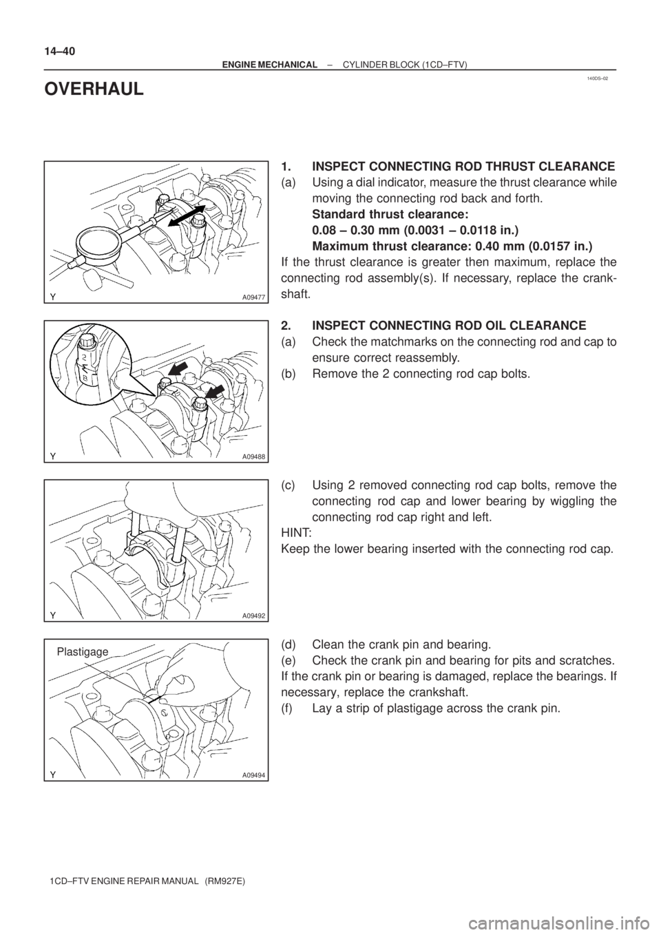
1. INSPECT CONNECTING ROD THRUST CLEARANCE
(a) Using a dial indicator, measure the thrust clearance while
moving the connecting rod back and forth.
Standard thrust clearance:
0.08 ± 0.30 mm (0.0031 ± 0.0118 in.)
Maximum thrust clearance: 0.40 mm (0.0157 in.)
If the thrust clearance is greater then maximum, replace the
connecting rod assembly(s). If necessary, replace the crank-
shaft.
2. INSPECT CONNECTING ROD OIL CLEARANCE
(a) Check the matchmarks on the connecting rod and cap to
ensure correct reassembly.
(b) Remove the 2 connecting rod cap bolts.
(c) Using 2 removed connecting rod cap bolts, remove the
connecting rod cap and lower bearing by wiggling the
connecting rod cap right and left.
HINT:
Keep the lower bearing inserted with the connecting rod cap.
(d) Clean the crank pin and bearing.
(e) Check the crank pin and bearing for pits and scratches.
If the crank pin or bearing is damaged, replace the bearings. If
necessary, replace the crankshaft.
(f) Lay a strip of plastigage across the crank pin.