Page 31 of 136

STARTING & CHARGING
SERVICE DATA
Starter assy (1.4kw)
Circle runout Maximum
Diameter Standard
Min")
0300Q±04
03±10
± SERVICE SPECIFICATIONSSTARTING & CHARGING
1CD±FTV ENGINE REPAIR MANUAL (RM927E)
STARTING & CHARGING
SERVICE DATA
Starter assy (1.4kw)
Circle runout Maximum
Diameter Standard
Minimum
Undercut depth Standard
Minimum
Brush length Standard
Minimum
0.05 mm(0.0020 in.)
30 mm (1.18 in.)
29 mm (1.14 in.)
0.6 mm (0.024 in.)
0.2 mm (0.008 in.)
15.5 mm (0.61 in.)
8.5 mm (0.3346 in.)
Starter assy (2.0kw)
Circle runout Maximum
Diameter Standard
Minimum
Undercut depth Standard
Minimum
Brush length Standard
Minimum
0.03 mm (0.0012 in.)
32.3 mm (1.272 in.)
30.5 mm (1.201 in.)
0.9 mm (0.035 in.)
0.3 mm (0.012 in.)
14.5 mm (0.571 in.)
9.0 mm (0.354 in.)
Starter assy (2.2kw)
Circle runout Maximum
Diameter Standard
Minimum
Undercut depth Standard
Minimum
Brush length Standard
Minimum
0.05 mm(0.0020 in.)
35 mm (1.378 in.)
34 mm (1.3386 in.)
0.7 mm (0.0276 in.)
0.2 mm (0.079 in.)
16.5 mm (0.6496 in.)
9.0 mm (0.3543 in.)
Generator assy (90A)
Rotor coil resistance at 20�C (68�F)
Slip ring diameter Standard
Minimum
Brush exposed length Standard
Minimum
2.7 ± 3.1 �
14.2 ± 14.4 mm (0.559 ± 0.567 in.)
12.8 mm (0.504 in.)
9.5 ± 11.5 mm (0.374 ± 0.453 in.)
1.5 mm (0.059 in.)
Generator assy (130A)
Rotor coil resistance at 20�C (68�F)
Slip ring diameter Standard
Minimum
Brush exposed length Standard
Minimum
2.3 ± 2.7 �
14.2 ± 14.4 mm (0.559 ± 0.567 in.)
14 mm (0.551 in.)
10.5 mm (0.4134 in.)
4.5 mm (0.177 in.)
Page 34 of 136

1CD±FTV ENGINE REPAIR MANUAL (RM927E)
OVERHAUL
1. REMOVE COMPRESSOR INLET ELBOW")
13035±01
B08025
Turn
A62443
Move
SST
B08048
Move
A62444
Open
SST
2mm 13±2
± INTAKETURBOCHARGER ASSEMBLY (1CD±FTV)
1CD±FTV ENGINE REPAIR MANUAL (RM927E)
OVERHAUL
1. REMOVE COMPRESSOR INLET ELBOW
(a) Remove 2 bolts and the compressor inlet elbow.
2. INSPECT TURBOCHARGER SUB±ASSY
(a) Inspect turbine shaft rotation
(1) Grasp the edge of the turbine shaft, and turn it.
(2) Check that the turbine shaft turns smoothly.
If the turbine shaft turns remarkably heavily or stuck, replace
the bearing housing. At that time, check also the interference
with the turbine housing and compressor housing.
(b) Inspect axial play of turbine shaft
(1) Using a dial indicator, insert the needle of the dial in-
dicator into the exhaust side.
(2) Move the turbine shaft in an axial direction, mea-
sure the axial play of the turbine shaft.
Maximum oil clearance: 0.09 mm (0.0035 in.) or less
If the axial play is greater than maximum, replace the bearing
housing. At that time, check also the interference with the tur-
bine housing and compressor housing.
(c) Inspect radial play of turbine shaft
(1) Using SST and a dial indicator, insert the needle of
the dial indicator into the oil outlet hole, and set it in
the center of the turbine shaft.
SST 09992±00600
(2) Move the turbine shaft in a radial direction, measure
the radial play of the turbine shaft.
Maximum oil clearance: 0.16 mm (0.0063 in.) or less
If the radial play is greater than maximum, replace the bearing
housing. At that time, check also the interference with the tur-
bine housing and compressor housing.
(d) Inspect actuator and waste gate valve operation.
(1) Disconnect the actuator hose from the compressor
housing.
(2) Using SST and a dial indicator, read the graduation
of SST when the actuator push rod moved 2 mm
(0.079 in.).
SST 09992±00242
Standard pressure:
129 ± 140 kPa (1.32 ± 1.43 kgf/cm
2, 18.7 ± 20.3 psi)
Page 37 of 136

13±5
1CD±FTV ENGINE REPAIR MANUAL (RM927E)
(e) Check that there is no severe damage on the seal su")
B08064
Seal Surface
Shroud Section
B08069
A62449
A62450
± INTAKETURBOCHARGER ASSEMBLY (1CD±FTV)
13±5
1CD±FTV ENGINE REPAIR MANUAL (RM927E)
(e) Check that there is no severe damage on the seal surface
with the bearing housing.
(f) Check that there is no bore made by the interference with
the turbine wheel in the shroud section.
If the turbine housing is having remarkable damage or bore, re-
place the turbine housing and bearing housing.
(g) Move the waste gate valve link and check that it runs
smoothly without sticking.
If the link is bad running, clean again. If it is bad running, even
after cleaning, replace the turbine housing.
7. CLEAN COMPRESSOR HOUSING SUB±ASSY
(a) Remove any old packing (FIPG) material and be careful
not to drop any oil on the contact surfaces of the compres-
sor housing and bearing housing.
(1) Using a razor blade and gasket scraper, remove all
the old packing (FIPG) material from the gasket sur-
faces.
(2) Thoroughly clean all components to remove all the
loose material.
(3) Using a non±residue solvent, clean both sealing
surfaces.
(b) Wipe off the dirt from the inside of the housing with a shop
rag.
(c) Check that there is no severe interference with the impel-
ler wheel.
If it is having bur made by a slight interference damage, remove
it with a sandpaper (No. 400) and blow with compressed air.
8. INSTALL BEARING HOUSING SUB±ASSY
(a) Align the pin of the turbine housing with the pin hole of the
bearing housing.
Page 41 of 136

Camshaft Oil
Seal Retainer
� Nozzle Holder Seal
Nozzle Leakage
Pipe Assy
Nozzle H")
140L3±01
A62602
Cylinder Head
Cover Sub±AssyGasket
Camshaft
Sub±Assy No.2
Camshaft
Sub±Assy No.1
18 (184, 13)
Camshaft Oil
Seal Retainer
� Nozzle Holder Seal
Nozzle Leakage
Pipe Assy
Nozzle Holder Clamp � O±Ring
� Injection Nozzle Seat
� Fuel Injector
Back±Up Ring No. 1
13 (135, 10)
Washer
Camshaft Carrier
Camshaft Bearing Cap
20 (204, 15)
Injector Assy
8.8 (90, 78 in.´lbf)
See page 14±3
1st 45 (460, 33)
2nd Turn 90 �
3rd Turn 90 �
4th Turn 90 �
22 (224, 16)
27 (275, 20)
� Gasket
� Gasket
20 (204, 15)
� Cylinder Head Gasket
� Oil Seal Plate Washer
x 18
Cylinder Head
Sub±Assy
�
Nozzle Holder Gasket
� Non±reusable partN´m (kgf´cm, ft´lbf)
: Specified torque
Oil Filler Cap Sub±Assy
Plate Washer
Camshaft Timing Pulley
88 (899, 65)
35 (357, 26)
Timing Belt Idler Sub±Assy No. 1
Timing Belt Idler Sub±Assy No. 2
47 (475, 34)
Crankshaft Timing Pulley
±
ENGINE MECHANICAL PARTIAL ENGINE ASSY (1CD±FTV)
14±1
1CD±FTV ENGINE REPAIR MANUAL (RM927E)
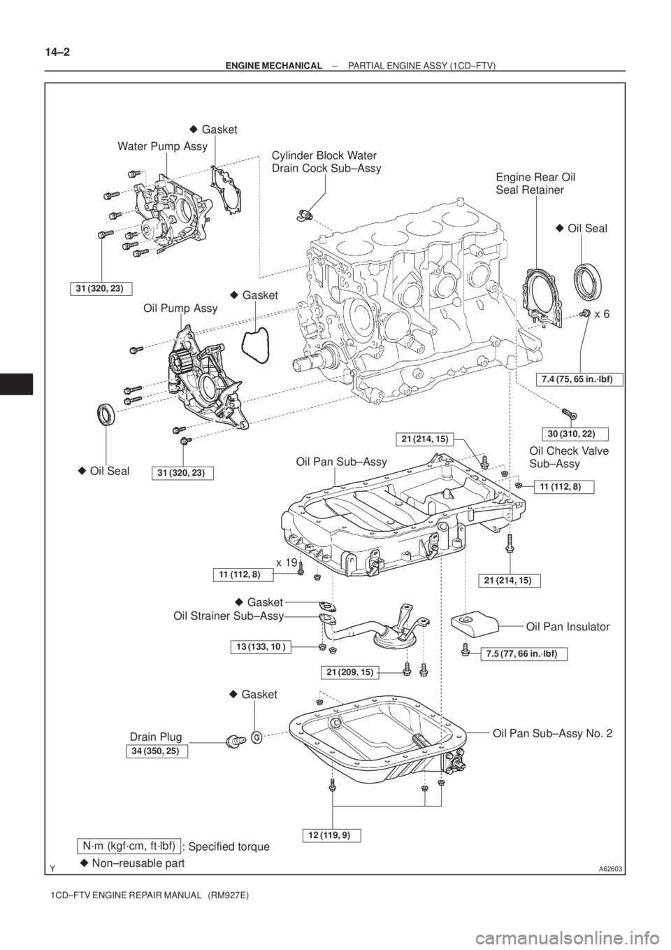
PARTIAL ENGINE ASSY (1CD±FTV)
COMPONENTS
Page 42 of 136
A62603
Engine Rear Oil
Seal Retainer
Oil Check Valve
Sub±Assy
Cylinder Block Water
Drain Cock Sub±Assy
31 (320, 23)
Water Pump Assy
21 (209, 15)
� Gasket � Gasket
x 6
� Gasket
� Oil Seal
Oil Pump Assy
� Oil Seal31 (320, 23)
7.4 (75, 65 in.´lbf)
11 (112, 8)
21 (214, 15)
Oil Pan Sub±Assy
11 (112, 8)x 19
Oil Strainer Sub±Assy
13 (133, 10 )
34 (350, 25)
Drain Plug
� Gasket
7.5 (77, 66 in.´lbf)
Oil Pan Insulator
Oil Pan Sub±Assy No. 2
12 (119, 9)
� Non±reusable part
N´m (kgf´cm, ft´lbf)
: Specified torque
21 (214, 15)30 (310, 22)
14±2
± ENGINE MECHANICALPARTIAL ENGINE ASSY (1CD±FTV)
1CD±FTV ENGINE REPAIR MANUAL (RM927E)
Page 43 of 136
140L4±01
A56691
A62591
A56692
A56693
± ENGINE MECHANICALPARTIAL ENGINE ASSY (1CD±FTV)
14±3
1CD±FTV ENGINE REPAIR MANUAL (RM927E)
OVERHAUL
1. REMOVE OIL FILLER CAP SUB±ASSY
2. REMOVE NOZZLE HOLDER SEAL
(a) Using a screwdriver, pry out the 4 nozzle holder seals.
3. REMOVE CYLINDER HEAD COVER SUB±ASSY
(a) Remove the 10 bolts, cylinder head cover and gasket.
4. REMOVE NOZZLE LEAKAGE PIPE ASSY
(a) Using a hexagon wrench (6mm), remove 4 hollow screws.
(b) Remove the union bolt, nozzle leakage pipe and 5 gas-
kets from the cylinder head and injector.
5. REMOVE NOZZLE HOLDER CLAMP
(a) Remove the 4 bolts, 4 washers and 4 nozzle holder
clamps.
Page 45 of 136
A57097
A57098
A09650
1 3
24
576
8
9
10 11
12
13 14
15
A09624
± ENGINE MECHANICALPARTIAL ENGINE ASSY (1CD±FTV)
14±5
1CD±FTV ENGINE REPAIR MANUAL (RM927E)
11. REMOVE CAMSHAFT OIL SEAL RETAINER
(a) Remove the 4 bolts.
(b) Using a screwdriver, remove the oil seal retainer by prying
the portions between the oil seal retainer and camshaft
bearing cap.
12. REMOVE WATER PUMP ASSY
(a) Remove the 7 bolts, water pump and gasket.
13. REMOVE CAMSHAFT SUB±ASSY, NO.2
(a) Uniformly loosen and remove the 15 bearing cap bolts in
several passes in the sequence shown.
(b) Remove the 5 bearing caps.
(c) Remove the camshaft No. 2.
14. REMOVE CAMSHAFT SUB±ASSY, NO.1
(a) Remove the camshaft from the cylinder head.
(b) Remove the camshaft carrier from the cylinder head.
Page 46 of 136

1CD±FTV ENGINE REPAIR MANUAL (RM927E)
15. REMOVE CYLI")
A09566
2
1 3
45
67 8
9
14 15 16
17 1211 1013
18
A09563
Pry
A56695
SSTSST
B08601
A56696
14±6
± ENGINE MECHANICALPARTIAL ENGINE ASSY (1CD±FTV)
1CD±FTV ENGINE REPAIR MANUAL (RM927E)
15. REMOVE CYLINDER HEAD SUB±ASSY
(a) Uniformly loosen the 18 cylinder head bolts in several
passes in the sequence shown. Remove the 18 cylinder
head bolts and plate washers.
NOTICE:
Cylinder head warpage or cracking could result from re-
moving bolts in incorrect order.
(b) Lift the cylinder head from the dowels on the cylinder
block, and place the cylinder head on wooden blocks on
a bench.
HINT:
If the cylinder head is lift off, pry between the cylinder head and
cylinder block with a screwdriver.
NOTICE:
Be careful not to damage the contact surfaces of the cylin-
der head and cylinder block.
16. REMOVE OIL PAN SUB±ASSY NO.2
(a) Remove the 16 bolts and 3 nuts.
(b) Insert the blade of SST between the No. 1 and No. 2 oil
pans, and cut off the applied seal and remove the No. 2
oil pan.
SST 09032±00100
NOTICE:
Be careful not to damage the contact surfaces of the No. 1
and No. 2 oil pans.
17. REMOVE OIL STRAINER SUB±ASSY
(a) Remove the 2 bolts, 2 nuts, oil strainer and gasket.

14±3
1CD±FTV ENGINE REPAIR MANUAL (RM927E)
OVERHAUL
1. REMOVE OIL FILLER CAP SUB±ASSY
2. REMOVE NOZZLE HOL")

14±5
1CD±FTV ENGINE REPAIR MANUAL (RM927E)
11. REMOVE CAMSHAFT OIL SEAL RETAINER
(a)")