Page 57 of 136

14±17
1CD±FTV ENGINE REPAIR MANUAL (RM927E)
42. INSTA")
A57098
A09600
Seal Width
2 ± 4 mm
Seal Packing
SST
A57101
Inward
Angle Sensor
A57102
Turn
± ENGINE MECHANICALPARTIAL ENGINE ASSY (1CD±FTV)
14±17
1CD±FTV ENGINE REPAIR MANUAL (RM927E)
42. INSTALL WATER PUMP ASSY
(a) Install a new gasket and the water pump with the 7bolts.
Torque: 31 N�m (320 kgf�cm, 23 ft�lbf)
43. INSTALL CAMSHAFT OIL SEAL RETAINER
(a) Apply seal packing to the oil seal retainer as shown in the
illustration.
Seal packing: Part No. 08826±00080 or equivalent
NOTICE:
�Install a nozzle that has been cut to a 2 ± 4 mm (0.08
± 0.16 in.) opening.
�Parts must be assembled within 15 minutes of ap-
plication. Otherwise the material must be removed
and reapplied.
�Immediately remove nozzle from the tube and rein-
stall the cap.
(b) Install the oil seal retainer with 4 bolts. Uniformly tighten
the 4 bolts in several passes.
Torque: 8.8 N�m (90 kgf�cm, 78 in.�lbf)
44. INSTALL CRANKSHAFT TIMING PULLEY
(a) Align the pulley set key with the key groove of the timing
pulley.
(b) Using SST and a hammer, tap in the timing pulley, facing
the angle sensor inward.
SST 09223±46011
45. INSTALL TIMING BELT IDLER SUB±ASSY NO.2
(a) Install the idler pulley with the bolt.
Torque: 47 N�m (475 kgf�cm, 34 ft�lbf)
(b) Check that the idler pulley moves smoothly.
Page 58 of 136

A62592
SST
B08252
B09792
Spring
Convex
14±18
± ENGINE MECHANICALPARTIAL ENGINE ASSY (1CD±FTV)
1CD±FTV ENGINE REPAIR MANUAL (RM927E)
46. INSTALL TIMING B")
A57103
Plate Washer
Hexagon
Wrench
(8mm)
A62592
SST
B08252
B09792
Spring
Convex
14±18
± ENGINE MECHANICALPARTIAL ENGINE ASSY (1CD±FTV)
1CD±FTV ENGINE REPAIR MANUAL (RM927E)
46. INSTALL TIMING BELT IDLER SUB±ASSY NO.1
(a) Using an hexagon wrench (8mm), install the plate washer
and idler pulley with the idler pulley shaft.
Torque: 35 N�m (350 kgf�cm, 25 ft�lbf)
(b) Check that the pulley bracket moves smoothly.
47. INSTALL CAMSHAFT TIMING PULLEY
(a) Install the pulley set key to the key groove of the cam-
shaft.
(b) Align the pulley set key with the key groove of the timing
pulley, and slide on the timing pulley.
(c) Using SST, install the pulley bolt.
SST 09960±10010 (09962±01000, 09963±01000)
Torque: 88 N�m (899 kgf�cm, 65 ft�lbf)
48. INSTALL INJECTOR ASSY
(a) Install 4 new nozzle seats to the cylinder head.
(b) Set the spring to each injector.
NOTICE:
Be sure to make the opening direction of the spring and the
direction of the injector positioning convex meet.
(c) Install a new back±up ring and O±ring to each injector.
(d) Apply a light coat of oil onto O±ring for each injector.
Page 59 of 136

14±19
1CD±FTV ENGINE REPAIR MANUAL (RM927E)
(e) Meet the injector positioning convex to the positionin")
B09793
Convex
Concave
B08249
Upward
B08253
± ENGINE MECHANICALPARTIAL ENGINE ASSY (1CD±FTV)
14±19
1CD±FTV ENGINE REPAIR MANUAL (RM927E)
(e) Meet the injector positioning convex to the positioning
concave at the cylinder head side and install the injector
to the cylinder head.
NOTICE:
�At this time, insert the injector until it touches the
nozzle sheet surface.
�When installing the injector to the cylinder head and
in case that the injector comes to float up with the
reaction of O±ring, pull out the injector once, install
it again.
�During the time after equipping the head cover and
before installing the injection pipe, install the irregu-
lar object prevention cover.
�Do not exchange the injector cylinder.
(f) Place the 4 nozzle holder clamps to each injector.
49. INSTALL NOZZLE HOLDER CLAMP
(a) Set the washer on the nozzle holder clamp as shown in
the illustration.
(b) Tighten the bolts.
HINT:
Apply a light coat of engine oil on the threads and under the
heads of the nozzle holder clamp bolts.
Torque: 27 N�m (275 kgf�cm, 20 ft�lbf)
NOTICE:
At this time, the clamp has its cam cap bolt as a fulcrum and
clip the injector at the fork portion.
Page 60 of 136

1CD±FTV ENGINE REPAIR MANUAL (RM927E)
50. INSTALL NOZZLE LEAKAGE PIPE A")
90�
180�
B08307
B08311
B08312
Plug
GasketOverflow Screw
Ball Spring 14±20
± ENGINE MECHANICALPARTIAL ENGINE ASSY (1CD±FTV)
1CD±FTV ENGINE REPAIR MANUAL (RM927E)
50. INSTALL NOZZLE LEAKAGE PIPE ASSY
(a) Place the leakage pipe and 5 new gaskets.
NOTICE:
Do the installation of the gasket craw within the angle
range shown in the illustration.
(b) Apply a light coat of oil onto 4 hollow screws and union
bolt.
(c) Tighten the 4 hollow screws and union bolt by hand.
(d) Tighten the 4 hollow screws and union bolt.
Torque:
Hollow screw 18 N�m (184 kgf�cm, 13 ft�lbf)
Union bolt 22 N�m (224 kgf�cm, 16 ft�lbf)
(e) Check that there is no leak from nozzle leakage pipe con-
nection.
(1) Disconnect the fuel hose, and remove the check
valve, No. 2 nozzle leakage pipe and gasket.
(2) Purchase a new check valve.
HINT:
Part No. 23122±27010
(3) Remove the plug, gasket, spring and ball.
(4) Install the plug with the gasket to the overflow
screw.
Torque: 9.8 N�m (100 kgf�cm, 7 ft.�lbf)
(5) Install the No. 2 nozzle leakage pipe and gasket
with the check valve to the cylinder head.
Torque: 21 N�m (214 kgf�cm, 15 ft�lbf)
(6) Apply a light coat of soapy water (any fluid to detect
fuel leakage) on the nozzle leakage pipe connec-
tion.
Page 62 of 136
140L5±01
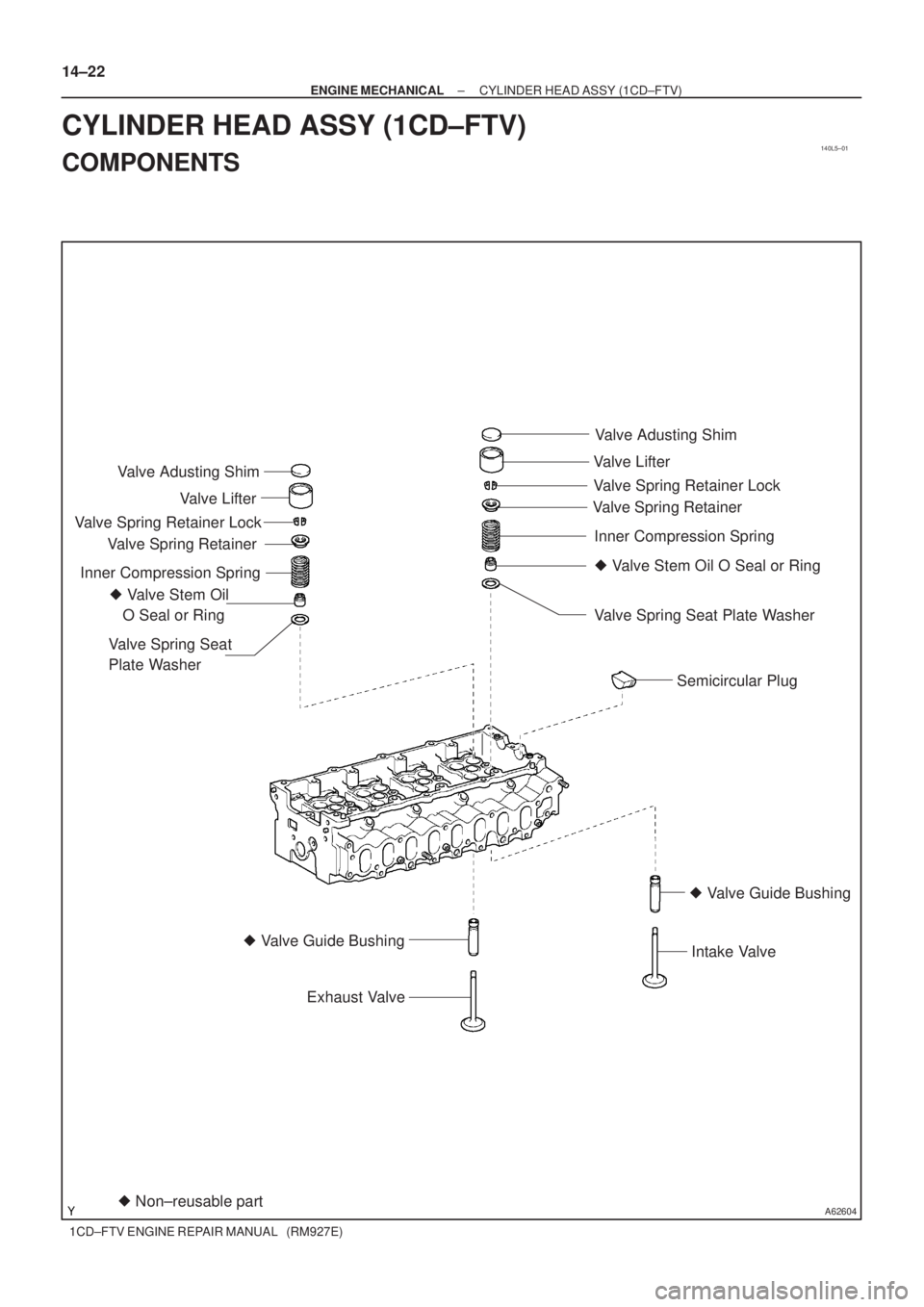
A62604� Non±reusable part � Valve Stem Oil
O Seal or RingValve Adusting Shim
Valve Lifter
Valve Spring Retainer
Valve Spring Retainer Lock
Inner Compression Spring
Valve Spring Seat
Plate Washer
� Valve Guide Bushing
Exhaust Valve
Semicircular Plug
� Valve Stem Oil O Seal or Ring Valve Adusting Shim
Valve Lifter
Valve Spring RetainerValve Spring Retainer Lock
Inner Compression Spring
Valve Spring Seat Plate Washer
� Valve Guide Bushing
Intake Valve
14±22
± ENGINE MECHANICALCYLINDER HEAD ASSY (1CD±FTV)
1CD±FTV ENGINE REPAIR MANUAL (RM927E)
CYLINDER HEAD ASSY (1CD±FTV)
COMPONENTS
Page 63 of 136
140DR±03
A56671
SST
A62594
SST
A09561
A09676
± ENGINE MECHANICALCYLINDER HEAD ASSY (1CD±FTV)
14±23
1CD±FTV ENGINE REPAIR MANUAL (RM927E)
OVERHAUL
1. REMOVE VALVE LIFTER
HINT:
Arrange the valve lifters in the correct order.
2. REMOVE INTAKE VALVE
(a) Using SST, compress the valve spring and remove the 2
keepers.
SST 09202±70020 (09202±00010)
(b) Remove the spring retainer, valve spring and valve.
3. REMOVE EXHAUST VALVE
(a) Using SST, compress the valve spring and remove the 2
keepers.
SST 09202±70020 (09202±00010)
(b) Remove the spring retainer, valve spring and valve.
4. REMOVE VALVE STEM OIL O SEAL OR RING
(a) Using needle±nose pliers, remove the oil seal.
5. REMOVE VALVE SPRING SEAT PLATE WASHER
(a) Using compressed air and a magnetic finger, remove the
spring seat by blowing air.
HINT:
Arrange the valves, valve springs, spring seats and spring re-
tainers in the correct order.
Page 66 of 136

1CD±FTV ENGINE REPAIR MANUAL (RM927E)
(c) Check the valve head margin thicknes")
A56051
Margin
Thickness
EM0801
A56052
Deviation
EM0281
A09539
14±26
± ENGINE MECHANICALCYLINDER HEAD ASSY (1CD±FTV)
1CD±FTV ENGINE REPAIR MANUAL (RM927E)
(c) Check the valve head margin thickness.
Standard margin thickness: 0.9 mm (0.035 in.)
Minimum margin thickness: 0.6 mm (0.024 in.)
12. INSPECT INNER COMPRESSION SPRING
(a) Using vernier calipers, measure the free length of the
valve spring.
Free length: 40.45 mm (1.5925 in.)
(b) Using a steel square, measure the deviation of the valve
spring.
Maximum deviation: 2.0 mm (0.079 in.)
(c) Using a spring tester, measure the tension of the valve
spring at the specified installed length.
Installed tension:
177 ± 195 N (18.0 ± 19.9 kgf, 39.7 ± 44.1 lbf) at 31.1 mm
(1.224 in.)
If the installed tension is not as specified, replace the valve
spring.
13. INSPECT VALVE GUIDE BUSHING OIL CLEARANCE
(a) using a caliper gauge, measure the inside diameter of the
guide bushing.
Bushing inside diameter:
6.010 ± 6.030 mm (0.2366 ± 0.2374 in.)
Page 67 of 136
A56674
SST
A56675
SST
± ENGINE MECHANICALCYLINDER HEAD ASSY (1CD±FTV)
14±27
1CD±FTV ENGINE REPAIR MANUAL (RM927E)
(b) Subtract the valve stem diameter measurement from the
guide bushing inside diameter measurement.
Standard oil clearance:
Intake0.025 ± 0.060 mm (0.0010 ± 0.0024 in.)
Exhaust0.035 ± 0.070 mm (0.0014 ± 0.0028 in.)
Maximum oil clearance:
Intake0.08 mm (0.0031 in.)
Exhaust0.10 mm (0.0039 in.)
14. REMOVE INTAKE VALVE GUIDE BUSH
(a) Heat the cylinder head to 80 ± 100�C (176 ± 212�F).
(b) Using SST and a hammer, tap out the guide bushing.
SST 09201±10000 (09201±01060), 09950±70010
(09951±07100)
15. REMOVE EXHAUST VALVE GUIDE BUSH
(a) Heat the cylinder head to 80 ± 100�C (176 ± 212�F).
(b) Using SST and a hammer, tap out the guide bushing.
SST 09201±10000 (09201±01060), 09950±70010
(09951±07100)

14±23
1CD±FTV ENGINE REPAIR MANUAL (RM927E)
OVERHAUL
1. REMOVE VALVE LIFTER
HINT:
Arrange the valve")

14±27
1CD±FTV ENGINE REPAIR MANUAL (RM927E)
(b) Subtract the valve stem diameter measurement from the
guide bushing inside")