Page 8 of 136
01±8
± INTRODUCTIONTERMS
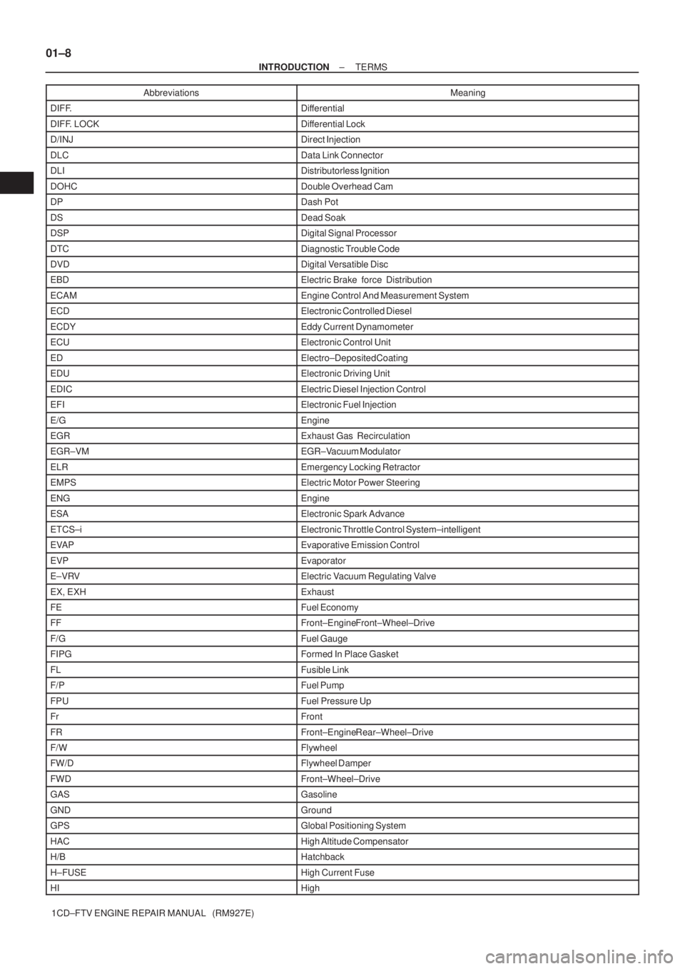
1CD±FTV ENGINE REPAIR MANUAL (RM927E)Abbreviations Meaning
DIFF.Differential
DIFF. LOCKDifferential Lock
D/INJDirect Injection
DLCData Link Connector
DLIDistributorless Ignition
DOHCDouble Overhead Cam
DPDash Pot
DSDead Soak
DSPDigital Signal Processor
DTCDiagnostic Trouble Code
DVDDigital Versatible Disc
EBDElectric Brake force Distribution
ECAMEngine Control And Measurement System
ECDElectronic Controlled Diesel
ECDYEddy Current Dynamometer
ECUElectronic Control Unit
EDElectro±Deposited Coating
EDUElectronic Driving Unit
EDICElectric Diesel Injection Control
EFIElectronic Fuel Injection
E/GEngine
EGRExhaust Gas Recirculation
EGR±VMEGR±Vacuum Modulator
ELREmergency Locking Retractor
EMPSElectric Motor Power Steering
ENGEngine
ESAElectronic Spark Advance
ETCS±iElectronic Throttle Control System±intelligent
EVAPEvaporative Emission Control
EVPEvaporator
E±VRVElectric Vacuum Regulating Valve
EX, EXHExhaust
FEFuel Economy
FFFront±Engine Front±Wheel±Drive
F/GFuel Gauge
FIPGFormed In Place Gasket
FLFusible Link
F/PFuel Pump
FPUFuel Pressure Up
FrFront
FRFront±Engine Rear±Wheel±Drive
F/WFlywheel
FW/DFlywheel Damper
FWDFront±Wheel±Drive
GASGasoline
GNDGround
GPSGlobal Positioning System
HACHigh Altitude Compensator
H/BHatchback
H±FUSEHigh Current Fuse
HIHigh
Page 10 of 136
01±10
± INTRODUCTIONTERMS
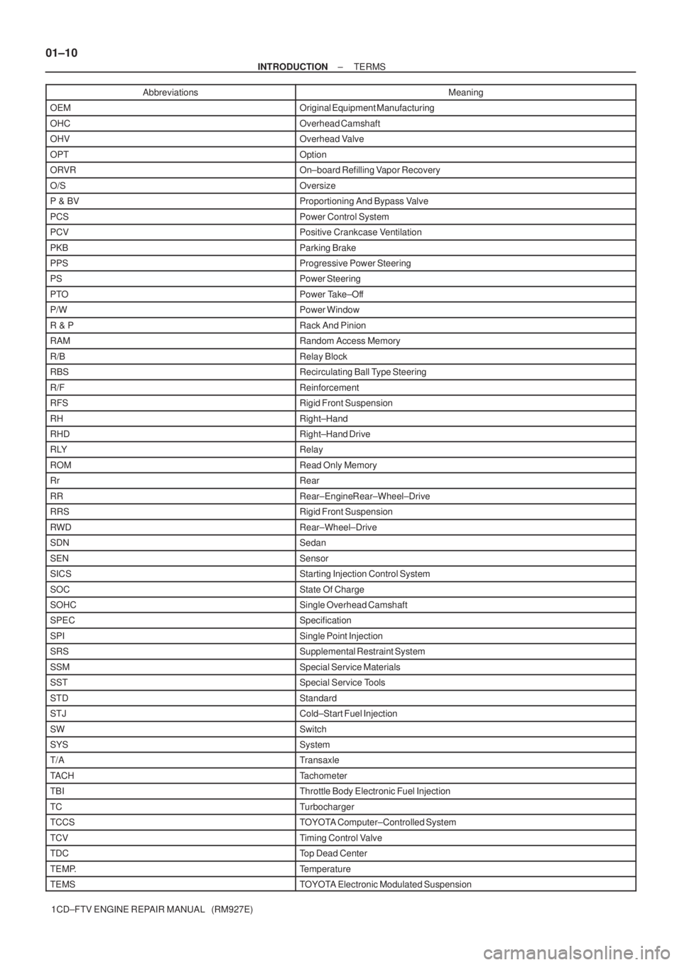
1CD±FTV ENGINE REPAIR MANUAL (RM927E)Abbreviations Meaning
OEMOriginal Equipment Manufacturing
OHCOverhead Camshaft
OHVOverhead Valve
OPTOption
ORVROn±board Refilling Vapor Recovery
O/SOversize
P & BVProportioning And Bypass Valve
PCSPower Control System
PCVPositive Crankcase Ventilation
PKBParking Brake
PPSProgressive Power Steering
PSPower Steering
PTOPower Take±Off
P/WPower Window
R & PRack And Pinion
RAMRandom Access Memory
R/BRelay Block
RBSRecirculating Ball Type Steering
R/FReinforcement
RFSRigid Front Suspension
RHRight±Hand
RHDRight±Hand Drive
RLYRelay
ROMRead Only Memory
RrRear
RRRear±Engine Rear±Wheel±Drive
RRSRigid Front Suspension
RWDRear±Wheel±Drive
SDNSedan
SENSensor
SICSStarting Injection Control System
SOCState Of Charge
SOHCSingle Overhead Camshaft
SPECSpecification
SPISingle Point Injection
SRSSupplemental Restraint System
SSMSpecial Service Materials
SSTSpecial Service Tools
STDStandard
STJCold±Start Fuel Injection
SWSwitch
SYSSystem
T/ATransaxle
TACHTachometer
TBIThrottle Body Electronic Fuel Injection
TCTurbocharger
TCCSTOYOTA Computer±Controlled System
TCVTiming Control Valve
TDCTop Dead Center
TEMP.Temperature
TEMSTOYOTA Electronic Modulated Suspension
Page 11 of 136
± INTRODUCTIONTERMS
01±11
1CD±FTV ENGINE REPAIR MANUAL (RM927E)Abbreviations Meaning
TFTToyota Free±Tronic
TISTotal Information System For Vehicle Development
T/MTransmission
TMCTOYOTA Motor Corporation
TMMKTOYOTA Motor Manufacturing Kentucky, Inc.
TRCTraction Control System
TURBOTurbocharge
TWCThree±Way Catalyst
U/DUnderdrive
U/SUndersize
VCVVacuum Control Valve
VENTVentilator
VINVehicle Identification Number
VPSVariable Power Steering
VSCVehicle Stability Control
VSVVacuum Switching Valve
VTVVacuum Transmitting Valve
VVT±iVariable Valve Timing±intelligent
w/With
WGNWagon
W/HWire Harness
w/oWithout
WU±TWCWarm Up Three±way Catalytic Converter
WU±OCWarm Up Oxidation Catalytic Converter
1stFirst
2ndSecond
2WDTwo Wheel Drive Vehicle (4 x 2)
3rdThird
4thFourth
4WDFour Wheel Drive Vehicle (4 x 4)
4WSFour Wheel Steering System
5thFifth
Page 25 of 136
030KS±01
03±4
± SERVICE SPECIFICATIONSINTAKE
1CD±FTV ENGINE REPAIR MANUAL (RM927E)
INTAKE
SERVICE DATA
TurbochargerActuator pressure
Turbine wheel axial play Maximum
Turbine wheel radial play Maximum129 ± 140 kPa (1.32 ± 1.43 kgf/cm2, 18.7 ± 20.3 psi)
0.09 mm (0.0035 in.) or less
0.16 mm (0.0063 in.) or less
Page 35 of 136
A62445
Torx Socket Wrench
A62446
Matchmarks
A62447
A62448
Matchmarks
± INTAKETURBOCHARGER ASSEMBLY (1CD±FTV)
13±3
1CD±FTV ENGINE REPAIR MANUAL (RM927E)
(e) Move the actuator push rod, and check that the waste
gate valve is open.
If operation is not as specified, replace the actuator and/or tur-
bine housing.
NOTICE:
Never apply more than 161 kPa (1.64 kgf/cm
2, 28.5 psi) of
pressure on the actuator.
(f) Reconnect the actuator hose to the compressor housing.
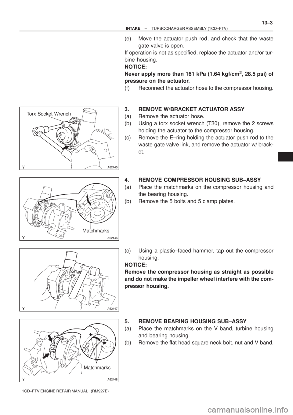
3. REMOVE W/BRACKET ACTUATOR ASSY
(a) Remove the actuator hose.
(b) Using a torx socket wrench (T30), remove the 2 screws
holding the actuator to the compressor housing.
(c) Remove the E±ring holding the actuator push rod to the
waste gate valve link, and remove the actuator w/ brack-
et.
4. REMOVE COMPRESSOR HOUSING SUB±ASSY
(a) Place the matchmarks on the compressor housing and
the bearing housing.
(b) Remove the 5 bolts and 5 clamp plates.
(c) Using a plastic±faced hammer, tap out the compressor
housing.
NOTICE:
Remove the compressor housing as straight as possible
and do not make the impeller wheel interfere with the com-
pressor housing.
5. REMOVE BEARING HOUSING SUB±ASSY
(a) Place the matchmarks on the V band, turbine housing
and bearing housing.
(b) Remove the flat head square neck bolt, nut and V band.
Page 36 of 136
B08059
B08067
B08068
Seal Surface
Shroud Section
B08065
Inside Diameter Section
B08066
13±4
± INTAKETURBOCHARGER ASSEMBLY (1CD±FTV)
1CD±FTV ENGINE REPAIR MANUAL (RM927E)
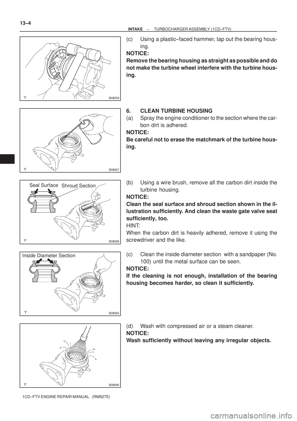
(c) Using a plastic±faced hammer, tap out the bearing hous-
ing.
NOTICE:
Remove the bearing housing as straight as possible and do
not make the turbine wheel interfere with the turbine hous-
ing.
6. CLEAN TURBINE HOUSING
(a) Spray the engine conditioner to the section where the car-
bon dirt is adhered.
NOTICE:
Be careful not to erase the matchmark of the turbine hous-
ing.
(b) Using a wire brush, remove all the carbon dirt inside the
turbine housing.
NOTICE:
Clean the seal surface and shroud section shown in the il-
lustration sufficiently. And clean the waste gate valve seat
sufficiently, too.
HINT:
When the carbon dirt is heavily adhered, remove it using the
screwdriver and the like.
(c) Clean the inside diameter section with a sandpaper (No.
100) until the metal surface can be seen.
NOTICE:
If the cleaning is not enough, installation of the bearing
housing becomes harder, so clean it sufficiently.
(d) Wash with compressed air or a steam cleaner.
NOTICE:
Wash sufficiently without leaving any irregular objects.
Page 37 of 136
B08064
Seal Surface
Shroud Section
B08069
A62449
A62450
± INTAKETURBOCHARGER ASSEMBLY (1CD±FTV)
13±5
1CD±FTV ENGINE REPAIR MANUAL (RM927E)
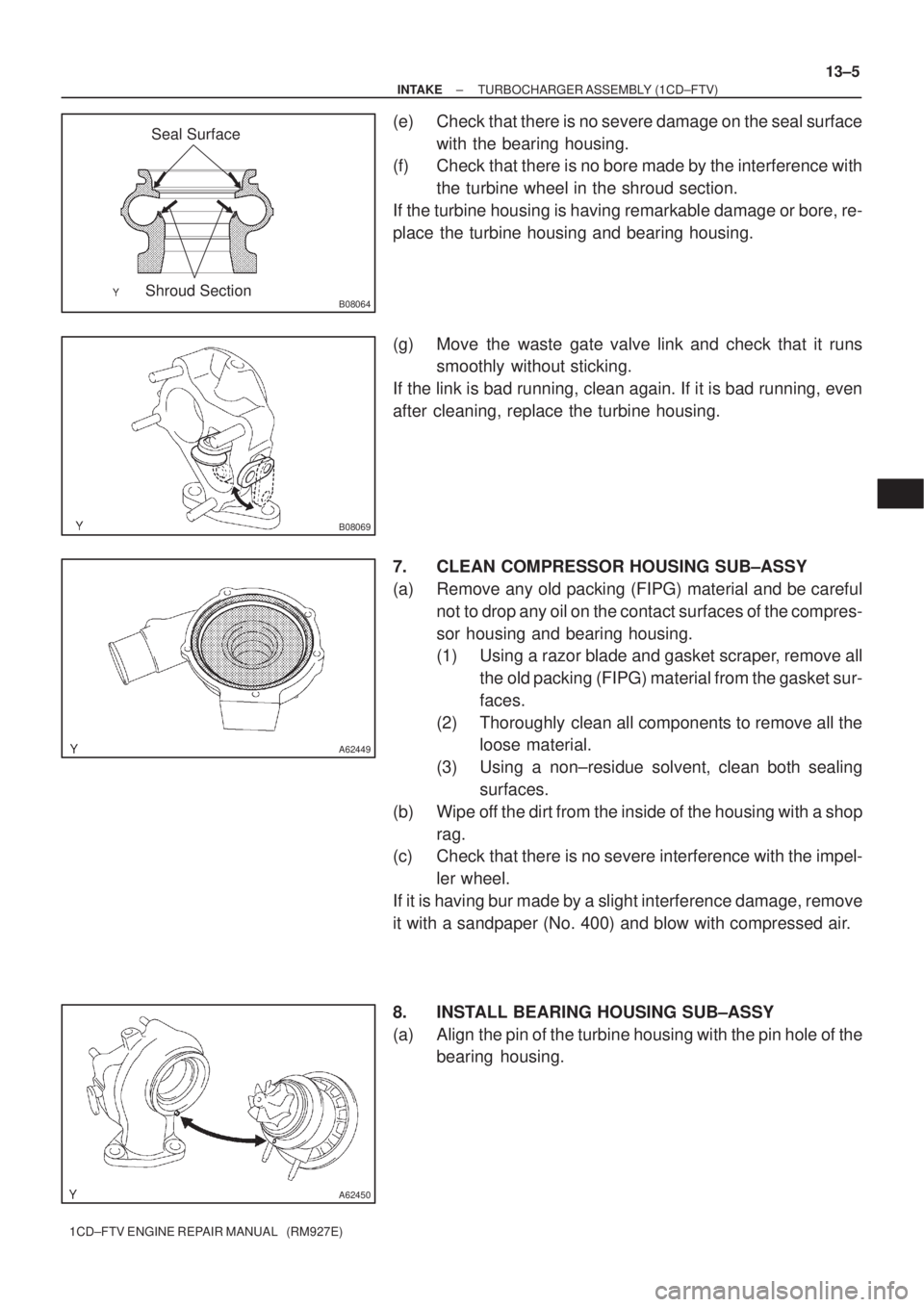
(e) Check that there is no severe damage on the seal surface
with the bearing housing.
(f) Check that there is no bore made by the interference with
the turbine wheel in the shroud section.
If the turbine housing is having remarkable damage or bore, re-
place the turbine housing and bearing housing.
(g) Move the waste gate valve link and check that it runs
smoothly without sticking.
If the link is bad running, clean again. If it is bad running, even
after cleaning, replace the turbine housing.
7. CLEAN COMPRESSOR HOUSING SUB±ASSY
(a) Remove any old packing (FIPG) material and be careful
not to drop any oil on the contact surfaces of the compres-
sor housing and bearing housing.
(1) Using a razor blade and gasket scraper, remove all
the old packing (FIPG) material from the gasket sur-
faces.
(2) Thoroughly clean all components to remove all the
loose material.
(3) Using a non±residue solvent, clean both sealing
surfaces.
(b) Wipe off the dirt from the inside of the housing with a shop
rag.
(c) Check that there is no severe interference with the impel-
ler wheel.
If it is having bur made by a slight interference damage, remove
it with a sandpaper (No. 400) and blow with compressed air.
8. INSTALL BEARING HOUSING SUB±ASSY
(a) Align the pin of the turbine housing with the pin hole of the
bearing housing.
Page 38 of 136
A62451
A62452
A62960
Old V Band
New V Band
Matchmark
13±6
± INTAKETURBOCHARGER ASSEMBLY (1CD±FTV)
1CD±FTV ENGINE REPAIR MANUAL (RM927E)
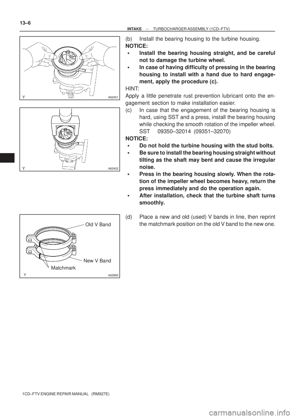
(b) Install the bearing housing to the turbine housing.
NOTICE:
�Install the bearing housing straight, and be careful
not to damage the turbine wheel.
�In case of having difficulty of pressing in the bearing
housing to install with a hand due to hard engage-
ment, apply the procedure (c).
HINT:
Apply a little penetrate rust prevention lubricant onto the en-
gagement section to make installation easier.
(c) In case that the engagement of the bearing housing is
hard, using SST and a press, install the bearing housing
while checking the smooth rotation of the impeller wheel.
SST 09350±32014 (09351±32070)
NOTICE:
�Do not hold the turbine housing with the stud bolts.
�Be sure to install the bearing housing straight without
tilting as the shaft may bent and cause the irregular
noise.
�Press in the bearing housing slowly. When the rota-
tion of the impeller wheel becomes heavy, return the
press immediately and do the operation again.
�After installation, check that the turbine shaft turns
smoothly.
(d) Place a new and old (used) V bands in line, then reprint
the matchmark position on the old V band to the new one.