Page 3 of 2870

HVAC SYSTEM
(HEATER, VENTILATOR AND A/C)
AC
Page
1. General Description ....................................................................................2
2. Refrigerant Pressure with Manifold Gauge Set .........................................25
3. Refrigerant Recovery Procedure...............................................................26
4. Refrigerant Charging Procedure ...............................................................27
5. Refrigerant Leak Check ............................................................................30
6. Compressor Oil .........................................................................................31
7. Blower Motor Unit Assembly .....................................................................32
8. Blower Resistor (Manual A/C Model) ........................................................33
9. Heater Core...............................................................................................34
10. Control Unit ...............................................................................................35
11. Compressor...............................................................................................36
12. Condenser.................................................................................................37
13. Condenser (Sub Fan)................................................................................38
14. Heater Cooling Unit ...................................................................................39
15. Evaporator.................................................................................................40
16. Hose and Tube..........................................................................................41
17. Relay and Fuse .........................................................................................42
18. Pressure Switch (Triple Pressure Switch) .................................................43
19. Ambient Sensor (Auto A/C Model) ............................................................44
20. Sunload Sensor (Auto A/C Model) ............................................................45
21. Air Vent Grille ............................................................................................46
22. Heater Duct ...............................................................................................47
23. Heater Vent Duct.......................................................................................48
24. Heater Cock Solenoid Valve .....................................................................49
25. General Diagnostics ..................................................................................50
Page 4 of 2870

AC-2
HVAC SYSTEM (HEATER, VENTILATOR AND A/C)
General Description
1. General Description
A: SPECIFICATION
1. HEATER SYSTEM
2. A/C SYSTEM
AUTO A/C MODEL
Item Specifications Condition
Heating capacity5.0 kW (4,300 kcal/h,
17,062 BTU/h) or more• Mode selector switch: HEAT
• Temperature control switch: FULL HOT
• Temperature difference between hot water
and inlet air: 65°C (149°F)
• Hot water flow rate: 3602 (95.1 US gal, 79.2
Imp gal)/h
Air flow rate
280 m
3 (9,888 cu ft)/hHeat mode (FRESH), FULL HOT at 12.5 V
Max air flow rate
480 m
3 (16,951 cu ft)/h• Temperature control switch: FULL COLD
• Blower fan speed: 4th position
• Mode selector lever: RECIRC
Heater core size
(height×length×width)134.1×224.3×32 mm
(5.28×8.83×1.26 in)—
Blower motorTy p eAuto A/C (Brushless motor)
230 W or less12.5 V
Manual A/C (Cylinder motor)
260 W or less12.5 V
Fan type and size
(diameter×width)Sirocco fan type
150×75 mm (5.91×2.95 in)—
Item Specifications
Type of air conditioner Reheat air-mix type
Cooling capacity5.1 kW
(4,386 kcal/h, 17,403 BTU/h)
RefrigerantHFC-134a (CH
2FCF3)
[0.6±0.05 kg (1.32±0.11 lb)]
CompressorType Vane rotary, fix volume (DKV-14G)
Discharge
140 cm
3 (8.54 cu in)/rev
Max. permissible speed 7,000 rpm
Magnet clutchType Dry, single-disc type
Power consumption 38 W (DC 12 V-25°C)
Type of belt V-belt 4 PK
Pulley dia. (effective dia.) 125 mm (4.92 in)
Pulley ratio 1.064
CondenserType Corrugated fin (Sub cool type)
Core face area
0.234 m
2 (2.52 sq ft)
Core thickness 16 mm (0.63 in)
Radiation area
5.6 m
2 (62.28 sq ft)
Receiver drier Effective inner capacity
220 cm
3 (13.42 cu in)
Expansion valve Type External equalizing
EvaporatorType Single tank
Dimensions (W×H×T)176.5×266×60 mm
(6.95×10.47×2.36 in)
Blower fanFan type Sirocco fan
Outer diameter×width 150×75 mm (5.91×2.95 in)
Power consumption 230 W or less at 12.5 V
Page 6 of 2870
AC-4
HVAC SYSTEM (HEATER, VENTILATOR AND A/C)
General Description
CondenserType Corrugated fin (Sub cool type)
Core face area
0.234 m
2 (2.52 sq ft)
Core thickness 16 mm (0.63 in)
Radiation area
5.6 m
2 (6.26 sq ft)
Receiver drier Effective inner capacity
220 cm
3 (13.42 cu in)
Expansion valve Type External equalizing
EvaporatorType Single tank
Dimensions (W×H×T)176.5×266×60 mm
(6.95×10.47×2.36 in)
Blower fanFan type Sirocco fan
Outer diameter×width 150×75 mm (5.91×2.95 in)
Power consumption 260 W or less at 12.5 V
Condenser fan (Sub fan)Motor type Magnet
Power consumption2.5 L turbo model and turbo AT model for EC and
EK:
120 W at 12 V
Other model than above:
70 W at 12 V
Fan outer diameter 320 mm (12.6 in)
Radiator fan (Main fan)Motor type Magnet
Power consumption2.5 L turbo model and turbo AT model for EC and
EK:
120 W at 12 V
Other model than above:
70 W at 12 V
Fan outer diameter 320 mm (12.6 in)
Idling speed (A/C ON) MPFI model 800±100 rpm
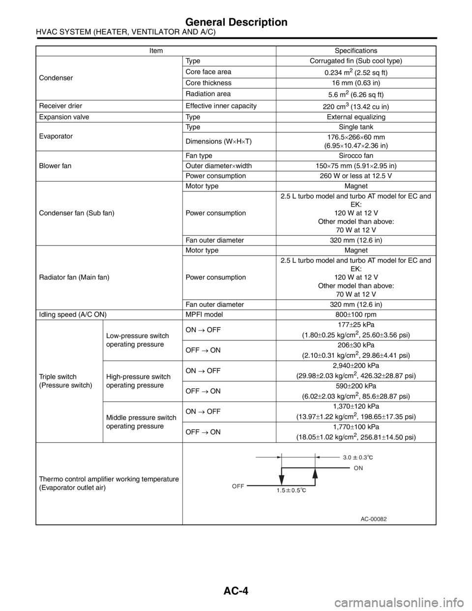
Triple switch
(Pressure switch)Low-pressure switch
operating pressureON → OFF177±25 kPa
(1.80±0.25 kg/cm
2, 25.60±3.56 psi)
OFF → ON206±30 kPa
(2.10±0.31 kg/cm
2, 29.86±4.41 psi)
High-pressure switch
operating pressureON → OFF2,940±200 kPa
(29.98±2.03 kg/cm
2, 426.32±28.87 psi)
OFF → ON590±200 kPa
(6.02±2.03 kg/cm
2, 85.6±28.87 psi)
Middle pressure switch
operating pressureON → OFF1,370±120 kPa
(13.97±1.22 kg/cm
2, 198.65±17.35 psi)
OFF → ON1,770±100 kPa
(18.05±1.02 kg/cm
2, 256.81±14.50 psi)
Thermo control amplifier working temperature
(Evaporator outlet air)Item Specifications
AC-00082
OFFON
3.0
0.3
Page 11 of 2870
AC-9
HVAC SYSTEM (HEATER, VENTILATOR AND A/C)
General Description
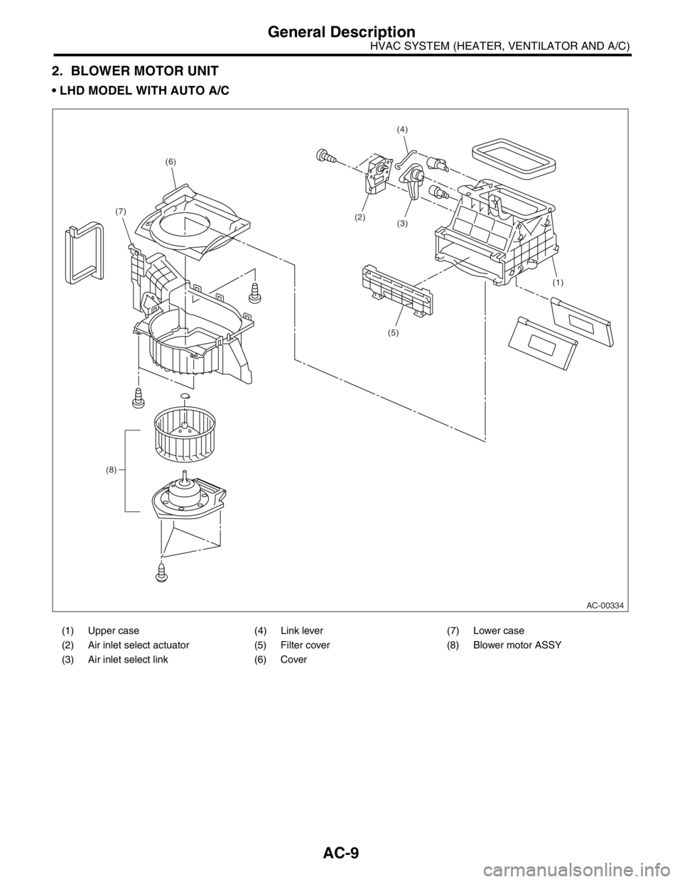
2. BLOWER MOTOR UNIT
LHD MODEL WITH AUTO A/C
(1) Upper case (4) Link lever (7) Lower case
(2) Air inlet select actuator (5) Filter cover (8) Blower motor ASSY
(3) Air inlet select link (6) Cover
AC-00334
(1)
(5)
(3)(2)
(4)
(6)
(7)
(8)
Page 12 of 2870
AC-10
HVAC SYSTEM (HEATER, VENTILATOR AND A/C)
General Description
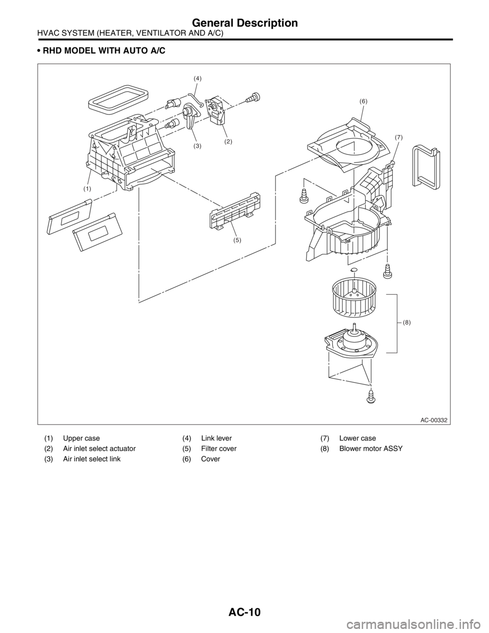
RHD MODEL WITH AUTO A/C
(1) Upper case (4) Link lever (7) Lower case
(2) Air inlet select actuator (5) Filter cover (8) Blower motor ASSY
(3) Air inlet select link (6) Cover
AC-00332
(1)
(5)
(3)(2)
(4)
(6)
(7)
(8)
Page 13 of 2870
AC-11
HVAC SYSTEM (HEATER, VENTILATOR AND A/C)
General Description
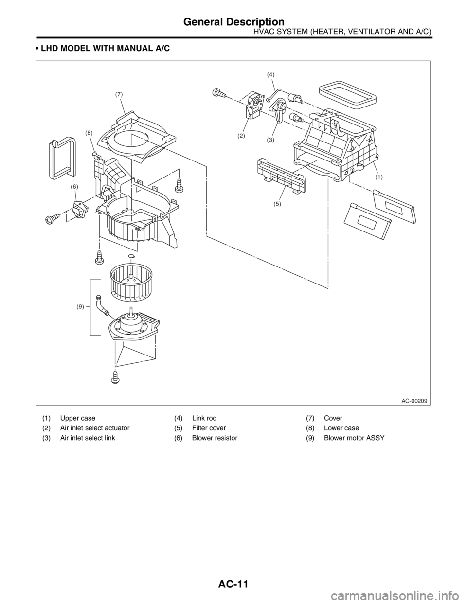
LHD MODEL WITH MANUAL A/C
(1) Upper case (4) Link rod (7) Cover
(2) Air inlet select actuator (5) Filter cover (8) Lower case
(3) Air inlet select link (6) Blower resistor (9) Blower motor ASSY
AC-00209
(1)
(5)
(3)(2)
(4)
(7)
(8)
(6)
(9)
Page 14 of 2870
AC-12
HVAC SYSTEM (HEATER, VENTILATOR AND A/C)
General Description
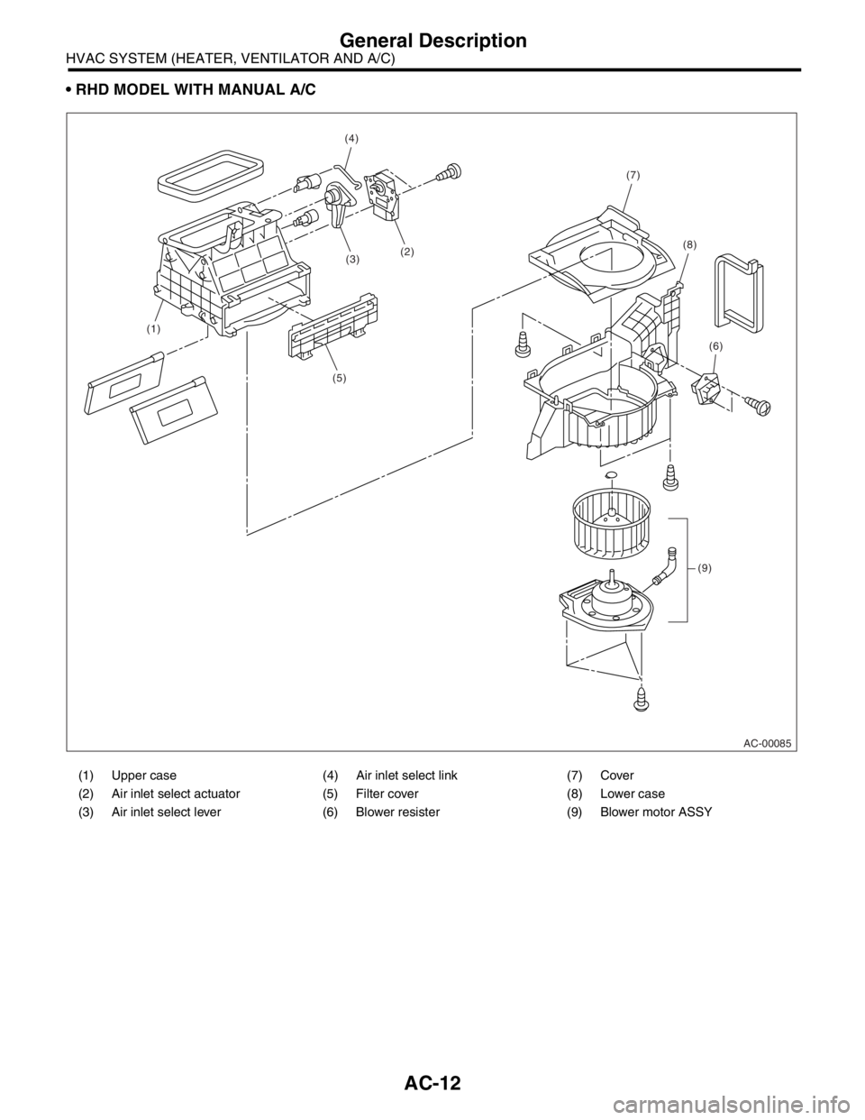
RHD MODEL WITH MANUAL A/C
(1) Upper case (4) Air inlet select link (7) Cover
(2) Air inlet select actuator (5) Filter cover (8) Lower case
(3) Air inlet select lever (6) Blower resister (9) Blower motor ASSY
AC-00085
(1)
(5)
(3)(2)
(4)
(7)
(8)
(6)
(9)
Page 34 of 2870
AC-32
HVAC SYSTEM (HEATER, VENTILATOR AND A/C)
Blower Motor Unit Assembly
7. Blower Motor Unit Assembly
A: REMOVAL
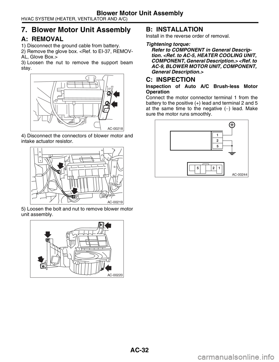
1) Disconnect the ground cable from battery.
2) Remove the glove box.
AL, Glove Box.>
3) Loosen the nut to remove the support beam
stay.
4) Disconnect the connectors of blower motor and
intake actuator resistor.
5) Loosen the bolt and nut to remove blower motor
unit assembly.
B: INSTALLATION
Install in the reverse order of removal.
Tightening torque:
Refer to COMPONENT in General Descrip-
tion.
COMPONENT, General Description.>
AC-9, BLOWER MOTOR UNIT, COMPONENT,
General Description.>
C: INSPECTION
Inspection of Auto A/C Brush-less Motor
Operation
Connect the motor connector terminal 1 from the
battery to the positive (+) lead and terminal 2 and 5
at the same time to the negative (−) lead. Make
sure the motor runs smoothly.
AC-00218
AC-00219
AC-00220
AC-00244
22
55
1 1