Page 1836 of 2870
EN(H4DOTC)-203
ENGINE (DIAGNOSTIC)
Diagnostic Procedure with Diagnostic Trouble Code (DTC)
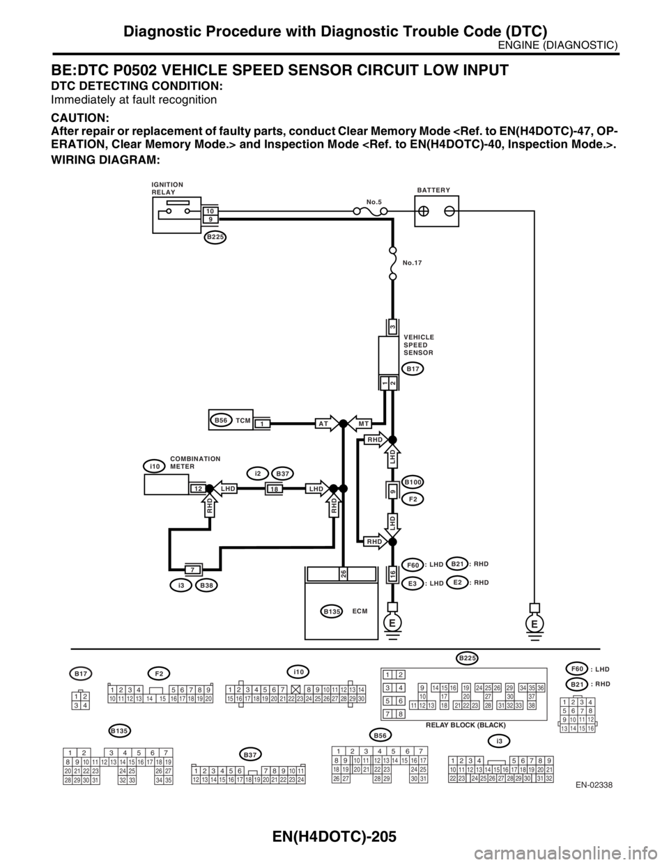
WIRING DIAGRAM:
EN-02337
No.18
No.17
EE
SBF-4
SBF-1
F17
B135 ECM
25
24F16
F16B72F2F27
F17
3412
1
2
SUB FAN
MOTOR
M
1
2
MAIN FAN
MOTOR
M
BATTERY
IGNITION
SWITCHB72
41
1234 5678910 11 12 13 14 15 16 17 18 19 203132333435
36
56789
1011121314
1516171819
2021222324
2526272829
1230
34
20A
F27 FAN
MODE
RELAY
A/C RELAY HOLDER
MAIN
FAN
RELAY SUB
FAN
RELAY
20A
29
25
27
28
30
34
32
317
5
9
2
1
4
3 8 6
B100F2
12B135
567
82 1
94 310
24 22 23 2511 12 13 14 15
26 27
2816 17 18 19
20 21
29 30 31 32 33 34 35
LHD : 10
RHD : 7
LHD : 11
RHD : 19 *
*1
2
*1
*2
: LHD
: RHD
F2
12345 678910
11
1219 20 21
13 14 15 1617
18 22
Page 1837 of 2870
EN(H4DOTC)-204
ENGINE (DIAGNOSTIC)
Diagnostic Procedure with Diagnostic Trouble Code (DTC)
Step Check Yes No
1 CHECK ANY OTHER DTC ON DISPLAY.Is any other DTC displayed? Inspect the rele-
vant DTC using
“List of Diagnostic
Trouble Code
(DTC)”.
EN(H4DOTC)-74,
List of Diagnostic
Trouble Code
(DTC).>Check the radiator
fan, fan motor and
thermostat and
replace the ther-
mostat when it is
stuck.
CO(H4SO)-35,
Radiator Main Fan
and Fan Motor.>
CO(H4SO)-40,
Radiator Sub Fan
and Fan Motor.>
Page 1838 of 2870

EN(H4DOTC)-205
ENGINE (DIAGNOSTIC)
Diagnostic Procedure with Diagnostic Trouble Code (DTC)
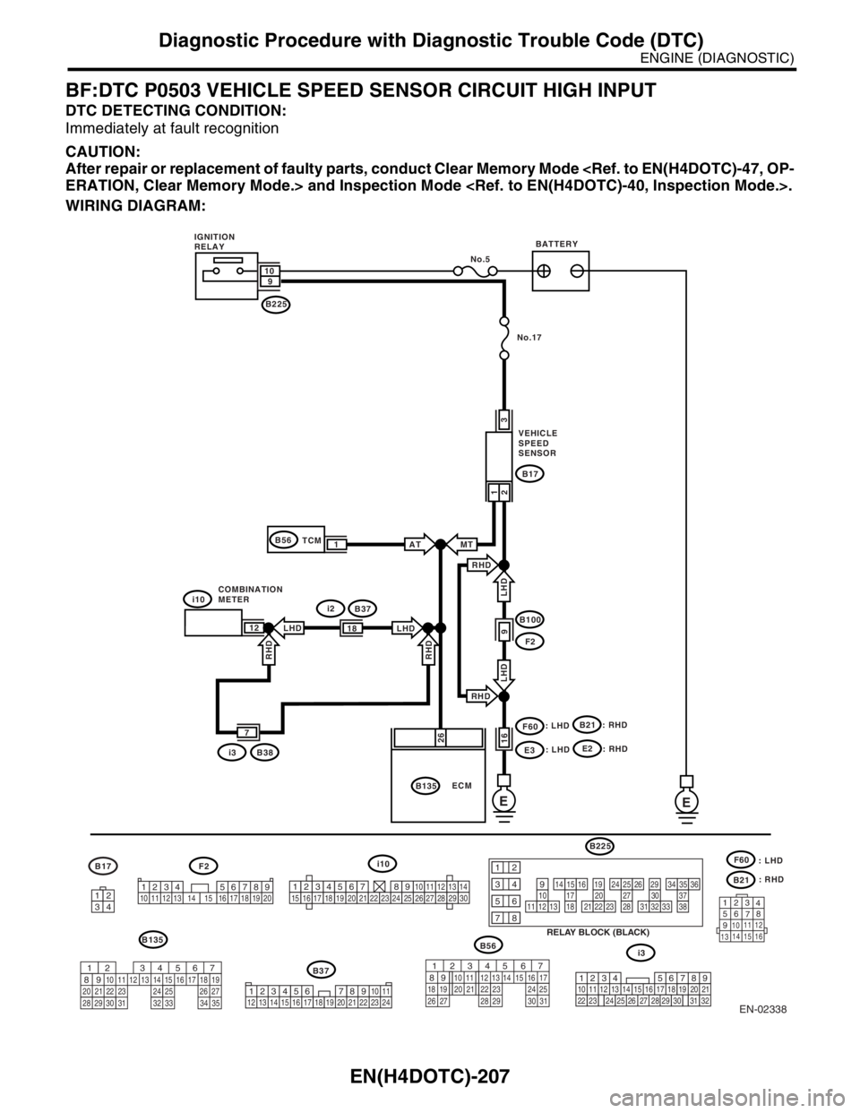
BE:DTC P0502 VEHICLE SPEED SENSOR CIRCUIT LOW INPUT
DTC DETECTING CONDITION:
Immediately at fault recognition
CAUTION:
After repair or replacement of faulty parts, conduct Clear Memory Mode
ERATION, Clear Memory Mode.> and Inspection Mode .
WIRING DIAGRAM:
EN-02338
E
i10
B135
B2259 10
No.5
: RHD
B21
F60
: LHD
: RHD
123
4
56
78
9
1011 12
1314 15 16
F2B17
i10i2B37
12
i3B38
7
E
F2
B100
B17
B21
E3
F60
9 LHD LHD
B135
26
No.17
: LHD
RHD
RHD
23
161
1B56ATMT
RHD
RHD
LHD LHD18
B37
i3
1234567891011121314151617181920212223242526272829301234 5678910 11 12 13 14 15 16 17 18 19 203412
567
82 1
94 310
24 22 23 2511 12 13 14 15
26 27
2816 17 18 19
20 21
29 30 31 32 33 34 35
B56
567
82 1
94 310
22 23 11 12 13 14 15
24 25
2616 17
18 19 20 21
27 28 29 30 3134
12 8910 11
12 13 14 15 16 17 18 19 20 21 22 23 2456 7219
32
1234
5610 11 12 13 14 15716
23 3019 20
22 26 27 28 29817
24 3118
25
: RHDE2
: LHD
RELAY BLOCK (BLACK)
10111213
1415161718
1920212223
2425262728
2930313233
3435363738
12
934
56
78
B225 BATTERY IGNITION
RELAY
COMBINATION
METERVEHICLE
SPEED
SENSOR
ECM TCM
Page 1839 of 2870

EN(H4DOTC)-206
ENGINE (DIAGNOSTIC)
Diagnostic Procedure with Diagnostic Trouble Code (DTC)
Step Check Yes No
1 CHECK TRANSMISSION TYPE.Is the transmission type AT? Go to step 2.Go to step 4.
2 CHECK HARNESS BETWEEN ECM AND
TCM CONNECTOR.
1) Turn the ignition switch to OFF.
2) Disconnect the connector from ECM and
TCM.
3) Measure the resistance of harness
between TCM connector and chassis ground.
Connector & terminal
(B56) No. 1 — Chassis ground:Is the resistance more than 1
MΩ?Go to step 3.Repair ground
short circuit in har-
ness between
ECM and TCM
connector.
3 CHECK POOR CONTACT.
Check poor contact in TCM connector.Is there poor contact in TCM
connector?Repair poor con-
tact in TCM con-
nector.Contact the SUB-
ARU dealer.
4 CHECK HARNESS BETWEEN VEHICLE
SPEED SENSOR AND ECM CONNECTOR.
1) Turn the ignition switch to OFF.
2) Disconnect the connector from vehicle
speed sensor ECM.
3) Measure the resistance of harness
between vehicle speed sensor connector and
chassis ground.
Connector & terminal
(B17) No. 1 — Chassis ground:Is the resistance more than 1
MΩ?Go to step 5.Repair ground
short circuit in har-
ness between
vehicle speed sen-
sor and ECM con-
nector.
5 CHECK POOR CONTACT.
Check poor contact in vehicle speed sensor
connector.Is there poor contact in vehicle
speed sensor connector?Repair poor con-
tact in vehicle
speed sensor con-
nector.Replace the vehi-
cle speed sensor.
Vehicle Speed
Sensor.>
Page 1840 of 2870

EN(H4DOTC)-207
ENGINE (DIAGNOSTIC)
Diagnostic Procedure with Diagnostic Trouble Code (DTC)
BF:DTC P0503 VEHICLE SPEED SENSOR CIRCUIT HIGH INPUT
DTC DETECTING CONDITION:
Immediately at fault recognition
CAUTION:
After repair or replacement of faulty parts, conduct Clear Memory Mode
ERATION, Clear Memory Mode.> and Inspection Mode .
WIRING DIAGRAM:
EN-02338
E
i10
B135
B2259 10
No.5
: RHD
B21
F60
: LHD
: RHD
123
4
56
78
9
1011 12
1314 15 16
F2B17
i10i2B37
12
i3B38
7
E
F2
B100
B17
B21
E3
F60
9 LHD LHD
B135
26
No.17
: LHD
RHD
RHD
23
161
1B56ATMT
RHD
RHD
LHD LHD18
B37
i3
1234567891011121314151617181920212223242526272829301234 5678910 11 12 13 14 15 16 17 18 19 203412
567
82 1
94 310
24 22 23 2511 12 13 14 15
26 27
2816 17 18 19
20 21
29 30 31 32 33 34 35
B56
567
82 1
94 310
22 23 11 12 13 14 15
24 25
2616 17
18 19 20 21
27 28 29 30 3134
12 8910 11
12 13 14 15 16 17 18 19 20 21 22 23 2456 7219
32
1234
5610 11 12 13 14 15716
23 3019 20
22 26 27 28 29817
24 3118
25
: RHDE2
: LHD
RELAY BLOCK (BLACK)
10111213
1415161718
1920212223
2425262728
2930313233
3435363738
12
934
56
78
B225 BATTERY IGNITION
RELAY
COMBINATION
METERVEHICLE
SPEED
SENSOR
ECM TCM
Page 1841 of 2870
EN(H4DOTC)-208
ENGINE (DIAGNOSTIC)
Diagnostic Procedure with Diagnostic Trouble Code (DTC)
Step Check Yes No
1 CHECK TRANSMISSION TYPE.Is the transmission type AT? Go to step 2.Go to step 3.
2 CHECK SPEEDOMETER OPERATION IN
COMBINATION METER.Does speedometer operate
normally?Go to step 3.Check the speed-
ometer.
IDI-13, Speedom-
eter.>
3 CHECK HARNESS BETWEEN ECM AND
COMBINATION METER CONNECTOR.
1) Turn the ignition switch to OFF.
2) Disconnect the connector from the combi-
nation meter.
3) Measure the resistance between ECM and
combination meter connector.
Connector & terminal
(B134) No. 1 — (i11) No. 2:Is the resistance less than 10
Ω?Repair the poor
contact in ECM
connector.Repair the har-
ness and connec-
tor.
N
OTE:
In this case repair
the following:
Open circuit in
harness between
ECM and combi-
nation meter con-
nector
Poor contact in
ECM connector.
Poor contact in
combination meter
connector
Poor contact in
coupling connector
Page 1842 of 2870

EN(H4DOTC)-209
ENGINE (DIAGNOSTIC)
Diagnostic Procedure with Diagnostic Trouble Code (DTC)
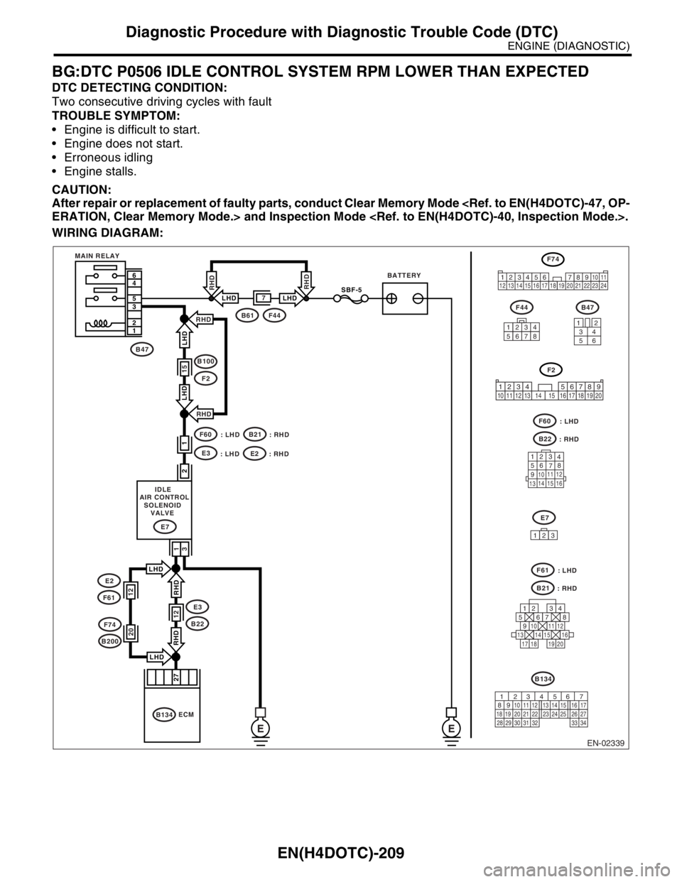
BG:DTC P0506 IDLE CONTROL SYSTEM RPM LOWER THAN EXPECTED
DTC DETECTING CONDITION:
Two consecutive driving cycles with fault
TROUBLE SYMPTOM:
Engine is difficult to start.
Engine does not start.
Erroneous idling
Engine stalls.
CAUTION:
After repair or replacement of faulty parts, conduct Clear Memory Mode
ERATION, Clear Memory Mode.> and Inspection Mode .
WIRING DIAGRAM:
EN-02339
BATTERY MAIN RELAY
EE
7 6
4
5
3
2
1RHD
RHDLHD LHD
27
IDLE
AIR CONTROL
SOLENOID
VALVE
1
3
E7
B47
B4734
12
56
F44
12345678
B134
F44B61
B134
ECM
2
1
RHD
RHD
LHD LHD
B100
F2
F60B21
E3
15
SBF-5
: LHD : RHD
F60
B22 : LHD
: RHD
E7
123
125678
131415169101112
34
17181920
123
4
56
78
9
1011 12
1314 15 16
F74
F61
B21 : LHD
: RHDRHD RHD
E3
B2212
LHD
LHD
12
E2
F61
F74
B200
34
128910 11
12 13 14 15 16 17 18 19 20 21 22 23 2456 7
F2
1234 5678910 11 12 13 14 15 16 17 18 19 20
E2
: LHD : RHD
20
56 7
82 1
94 310
24 22 23 25 11 12 13 14 15
26 27
2816 17
18 19 20 21
33 34 29
32 30 31
Page 1843 of 2870

EN(H4DOTC)-210
ENGINE (DIAGNOSTIC)
Diagnostic Procedure with Diagnostic Trouble Code (DTC)
Step Check Yes No
1 CHECK ANY OTHER DTC ON DISPLAY.Is any other DTC displayed? Inspect the rele-
vant DTC using
“List of Diagnostic
Trouble Code
(DTC)”.
EN(H4DOTC)-74,
List of Diagnostic
Trouble Code
(DTC).>
N
OTE:
In this case, it is
not necessary to
inspect DTC
P0506.Go to step 2.
2 CHECK IDLE AIR CONTROL SOLENOID
VALVE.
1) Turn the ignition switch to OFF.
2) Remove the idle air control solenoid valve
from the throttle body.
37, REMOVAL, Idle Air Control Solenoid
Va l ve. >
3) Using an air gun, force air into the idle air
control solenoid valve by-pass air inlet.Confirm
that forced air subsequently escapes from both
main air passage and assist air passage.Does air flow out? Go to step 3.Replace the idle
air control solenoid
valve.
FU(H4DOTC)-37,
Idle Air Control
Solenoid Valve.>
After replace, Go
to step 3.
3 CHECK IDLE AIR CONTROL SOLENOID
VALVE DUTY RATIO.
1) Turn the ignition switch to ON.
2) Start the engine, and warm-up the engine.
3) Turn all accessory switches to OFF.
4) Read the data of idle air control solenoid
duty ratio using Subaru Select Monitor or
OBD-II general scan tool.
NOTE:
Subaru Select Monitor
For detailed operation procedure, refer to
“READ CURRENT DATA SHOWN ON DIS-
PLAY FOR ENGINE”.
33, Subaru Select Monitor.>
OBD-II general scan tool
For detailed operation procedures, refer to the
OBD-II General Scan Tool Operation Manual.Is the duty ratio more than 60% Go to step 4.END.
4 CHECK BY-PASS AIR LINE.
1) Turn the ignition switch to OFF.
2) Remove the idle air control solenoid valve
from the throttle body.
37, REMOVAL, Idle Air Control Solenoid
Va l ve. >
3) Remove the throttle body from the intake
manifold.
REMOVAL, Throttle Body.>
4) Using an air gun, force air into the solenoid
valve installation area and throttle valve inte-
rior.Confirm that forced air subsequently
escapes from both these areas.Does air flow out? Replace the idle
air control solenoid
valve.
FU(H4DOTC)-37,
Idle Air Control
Solenoid Valve.>Replace the throt-
tle body.
FU(H4DOTC)-13,
Throttle Body.>