Page 2374 of 2870
4AT-61
AUTOMATIC TRANSMISSION
Control Valve Body
17.Control Valve Body
A: REMOVAL
1. NON-TURBO MODEL
1) Lift-up the vehicle.
2) Clean the transmission exterior.
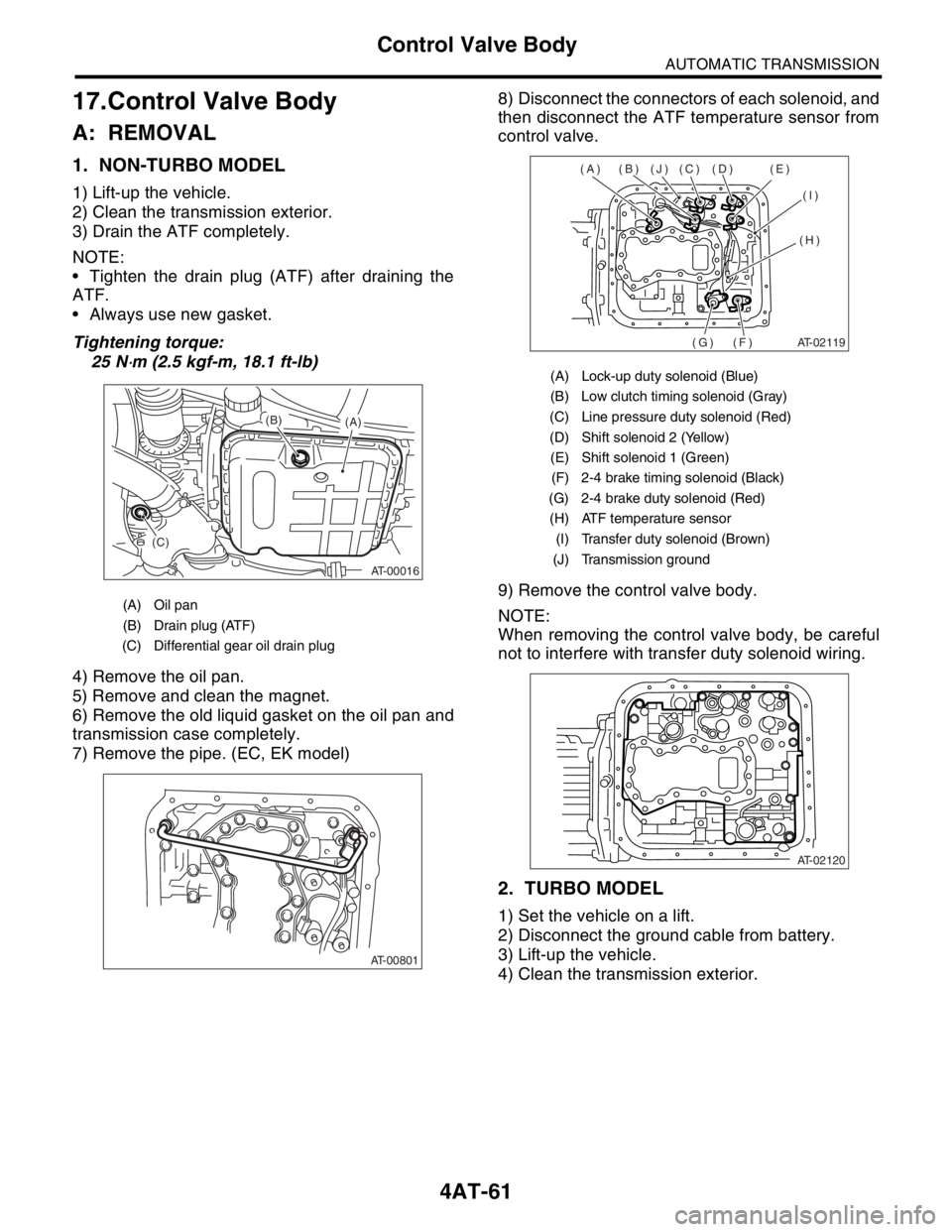
3) Drain the ATF completely.
NOTE:
Tighten the drain plug (ATF) after draining the
ATF.
Always use new gasket.
Tightening torque:
25 N
⋅m (2.5 kgf-m, 18.1 ft-lb)
4) Remove the oil pan.
5) Remove and clean the magnet.
6) Remove the old liquid gasket on the oil pan and
transmission case completely.
7) Remove the pipe. (EC, EK model)8) Disconnect the connectors of each solenoid, and
then disconnect the ATF temperature sensor from
control valve.
9) Remove the control valve body.
NOTE:
When removing the control valve body, be careful
not to interfere with transfer duty solenoid wiring.
2. TURBO MODEL
1) Set the vehicle on a lift.
2) Disconnect the ground cable from battery.
3) Lift-up the vehicle.
4) Clean the transmission exterior.
(A) Oil pan
(B) Drain plug (ATF)
(C) Differential gear oil drain plug
AT-00016
(A) (B)
(C)
AT-00801
(A) Lock-up duty solenoid (Blue)
(B) Low clutch timing solenoid (Gray)
(C) Line pressure duty solenoid (Red)
(D) Shift solenoid 2 (Yellow)
(E) Shift solenoid 1 (Green)
(F) 2-4 brake timing solenoid (Black)
(G) 2-4 brake duty solenoid (Red)
(H) ATF temperature sensor
(I) Transfer duty solenoid (Brown)
(J) Transmission ground
AT-02119
(A) (B) (J) (C) (D) (E)
(I)
(H)
(F) (G)
AT-02120
Page 2376 of 2870
4AT-63
AUTOMATIC TRANSMISSION
Control Valve Body
B: INSTALLATION
1. NON-TURBO MODEL
1) Set the range select lever in “N” range.
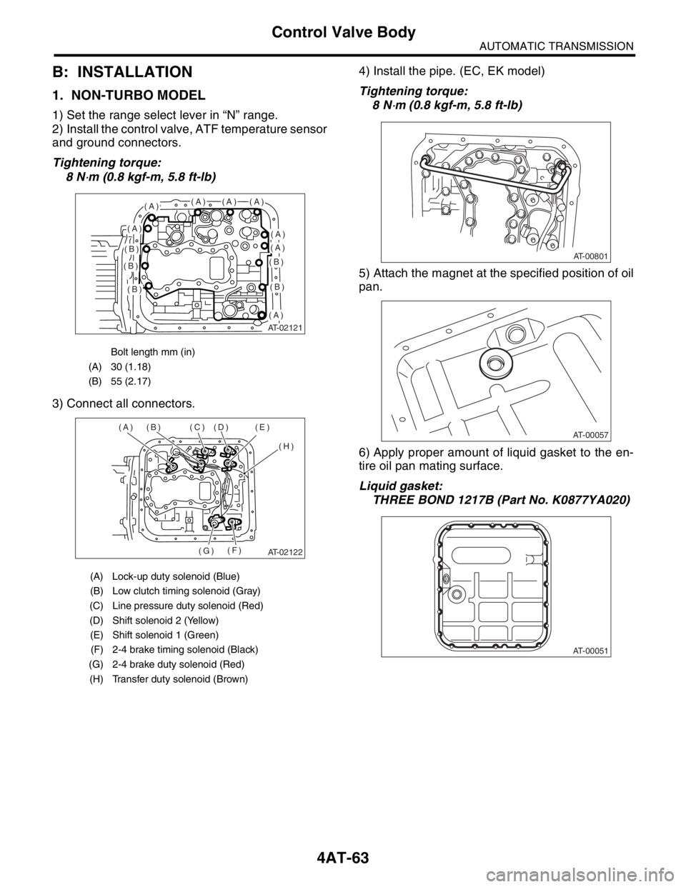
2) Install the control valve, ATF temperature sensor
and ground connectors.
Tightening torque:
8 N
⋅m (0.8 kgf-m, 5.8 ft-lb)
3) Connect all connectors.4) Install the pipe. (EC, EK model)
Tightening torque:
8 N
⋅m (0.8 kgf-m, 5.8 ft-lb)
5) Attach the magnet at the specified position of oil
pan.
6) Apply proper amount of liquid gasket to the en-
tire oil pan mating surface.
Liquid gasket:
THREE BOND 1217B (Part No. K0877YA020)
Bolt length mm (in)
(A) 30 (1.18)
(B) 55 (2.17)
(A) Lock-up duty solenoid (Blue)
(B) Low clutch timing solenoid (Gray)
(C) Line pressure duty solenoid (Red)
(D) Shift solenoid 2 (Yellow)
(E) Shift solenoid 1 (Green)
(F) 2-4 brake timing solenoid (Black)
(G) 2-4 brake duty solenoid (Red)
(H) Transfer duty solenoid (Brown)
AT-02121
(A)(A)(A)(A)
(A)(A)
(A)
(A)
(B)
(B)
(B)
(B)
(B)
AT-02122
(A) (B) (C) (D) (E)
(H)
(F)
(G)
AT-00801
AT-00057
AT-00051
Page 2384 of 2870
4AT-71
AUTOMATIC TRANSMISSION
Shift Solenoids, Duty Solenoids and ATF Temperature Sensor
19.Shift Solenoids, Duty Sole-
noids and ATF Temperature
Sensor
A: REMOVAL
1. SHIFT SOLENOID AND DUTY SOLE-
NOID
1) Lift-up the vehicle.
2) Clean the transmission exterior.
3) Drain the ATF completely.
4) Replace the gasket with new one, and then tight-
en the drain plug (ATF).
Tightening torque:
25 N
⋅m (2.5 kgf-m, 18.1 ft-lb)
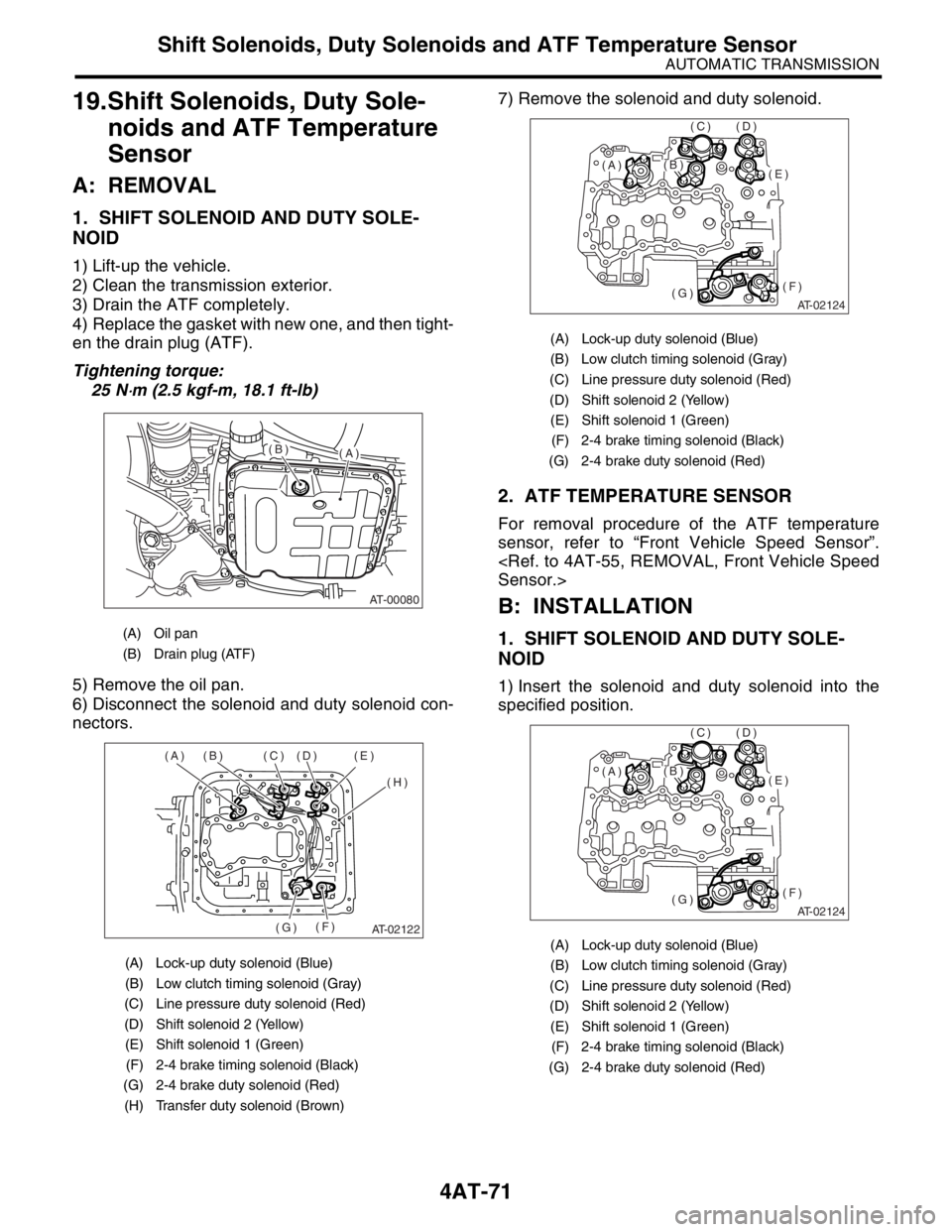
5) Remove the oil pan.
6) Disconnect the solenoid and duty solenoid con-
nectors.7) Remove the solenoid and duty solenoid.
2. ATF TEMPERATURE SENSOR
For removal procedure of the ATF temperature
sensor, refer to “Front Vehicle Speed Sensor”.
Sensor.>
B: INSTALLATION
1. SHIFT SOLENOID AND DUTY SOLE-
NOID
1) Insert the solenoid and duty solenoid into the
specified position.
(A) Oil pan
(B) Drain plug (ATF)
(A) Lock-up duty solenoid (Blue)
(B) Low clutch timing solenoid (Gray)
(C) Line pressure duty solenoid (Red)
(D) Shift solenoid 2 (Yellow)
(E) Shift solenoid 1 (Green)
(F) 2-4 brake timing solenoid (Black)
(G) 2-4 brake duty solenoid (Red)
(H) Transfer duty solenoid (Brown)
AT-00080
(A)(B)
AT-02122
(A) (B) (C) (D) (E)
(H)
(F)
(G)
(A) Lock-up duty solenoid (Blue)
(B) Low clutch timing solenoid (Gray)
(C) Line pressure duty solenoid (Red)
(D) Shift solenoid 2 (Yellow)
(E) Shift solenoid 1 (Green)
(F) 2-4 brake timing solenoid (Black)
(G) 2-4 brake duty solenoid (Red)
(A) Lock-up duty solenoid (Blue)
(B) Low clutch timing solenoid (Gray)
(C) Line pressure duty solenoid (Red)
(D) Shift solenoid 2 (Yellow)
(E) Shift solenoid 1 (Green)
(F) 2-4 brake timing solenoid (Black)
(G) 2-4 brake duty solenoid (Red)
AT-02124
(E)
(F)(G)
(D)(C)
(B)(A)
AT-02124
(E)
(F)(G)
(D)(C)
(B)(A)
Page 2385 of 2870
4AT-72
AUTOMATIC TRANSMISSION
Shift Solenoids, Duty Solenoids and ATF Temperature Sensor
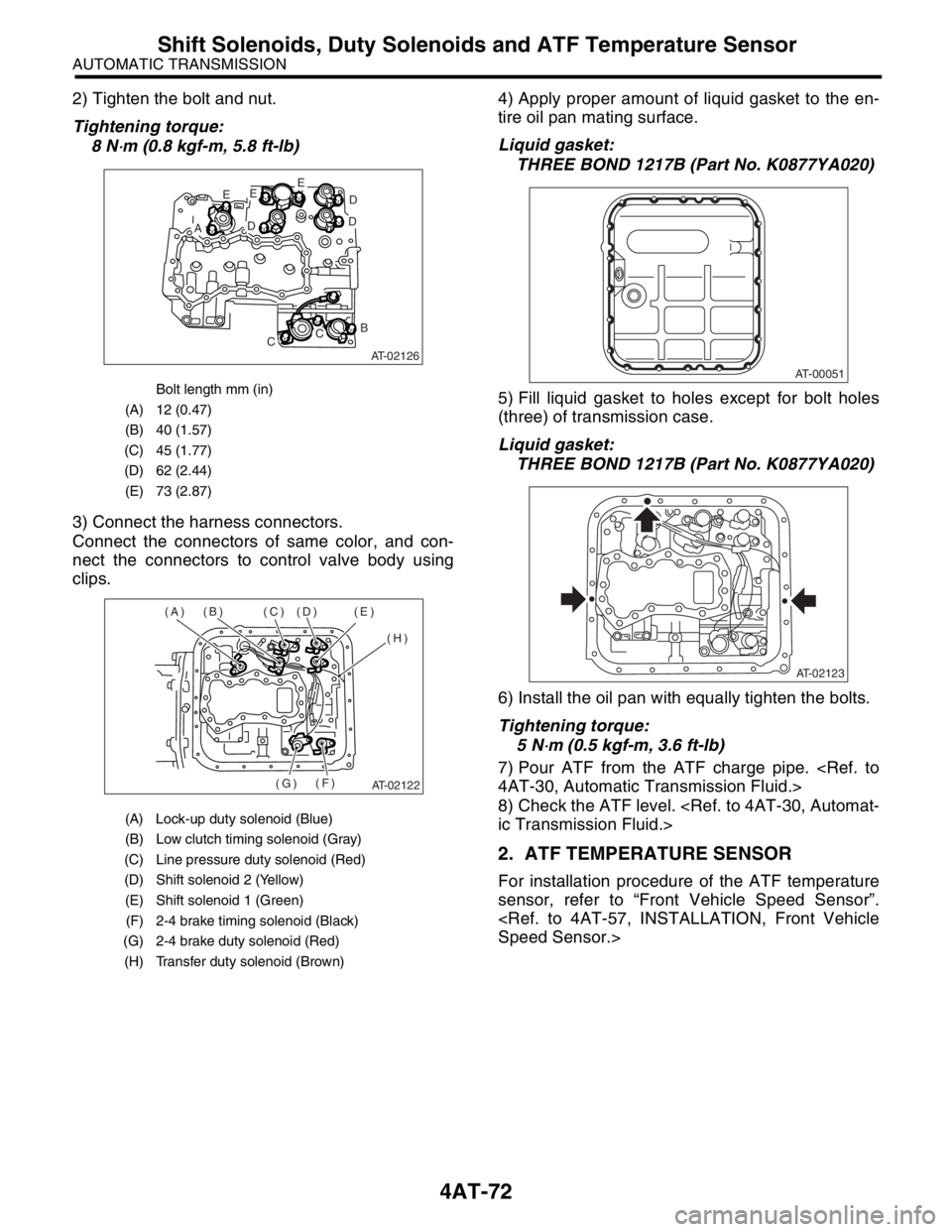
2) Tighten the bolt and nut.
Tightening torque:
8 N
⋅m (0.8 kgf-m, 5.8 ft-lb)
3) Connect the harness connectors.
Connect the connectors of same color, and con-
nect the connectors to control valve body using
clips.4) Apply proper amount of liquid gasket to the en-
tire oil pan mating surface.
Liquid gasket:
THREE BOND 1217B (Part No. K0877YA020)
5) Fill liquid gasket to holes except for bolt holes
(three) of transmission case.
Liquid gasket:
THREE BOND 1217B (Part No. K0877YA020)
6) Install the oil pan with equally tighten the bolts.
Tightening torque:
5 N
⋅m (0.5 kgf-m, 3.6 ft-lb)
7) Pour ATF from the ATF charge pipe.
4AT-30, Automatic Transmission Fluid.>
8) Check the ATF level.
ic Transmission Fluid.>
2. ATF TEMPERATURE SENSOR
For installation procedure of the ATF temperature
sensor, refer to “Front Vehicle Speed Sensor”.
Speed Sensor.>
Bolt length mm (in)
(A) 12 (0.47)
(B) 40 (1.57)
(C) 45 (1.77)
(D) 62 (2.44)
(E) 73 (2.87)
(A) Lock-up duty solenoid (Blue)
(B) Low clutch timing solenoid (Gray)
(C) Line pressure duty solenoid (Red)
(D) Shift solenoid 2 (Yellow)
(E) Shift solenoid 1 (Green)
(F) 2-4 brake timing solenoid (Black)
(G) 2-4 brake duty solenoid (Red)
(H) Transfer duty solenoid (Brown)
AT-02126
E
AD
EE
D
D
B
CC
AT-02122
(A) (B) (C) (D) (E)
(H)
(F)
(G)
AT-00051
AT-02123
Page 2386 of 2870
4AT-73
AUTOMATIC TRANSMISSION
Transfer Duty Solenoid and Valve Body
20.Transfer Duty Solenoid and
Valve Body
A: REMOVAL
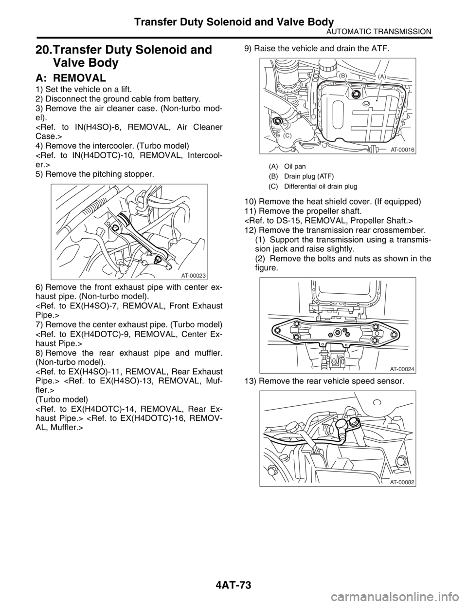
1) Set the vehicle on a lift.
2) Disconnect the ground cable from battery.
3) Remove the air cleaner case. (Non-turbo mod-
el).
Case.>
4) Remove the intercooler. (Turbo model)
er.>
5) Remove the pitching stopper.
6) Remove the front exhaust pipe with center ex-
haust pipe. (Non-turbo model).
Pipe.>
7) Remove the center exhaust pipe. (Turbo model)
haust Pipe.>
8) Remove the rear exhaust pipe and muffler.
(Non-turbo model).
Pipe.>
fler.>
(Turbo model)
haust Pipe.>
AL, Muffler.>9) Raise the vehicle and drain the ATF.
10) Remove the heat shield cover. (If equipped)
11) Remove the propeller shaft.
12) Remove the transmission rear crossmember.
(1) Support the transmission using a transmis-
sion jack and raise slightly.
(2) Remove the bolts and nuts as shown in the
figure.
13) Remove the rear vehicle speed sensor.
AT-00023
(A) Oil pan
(B) Drain plug (ATF)
(C) Differential oil drain plug
AT-00016
(A) (B)
(C)
AT-00024
AT-00082
Page 2387 of 2870
4AT-74
AUTOMATIC TRANSMISSION
Transfer Duty Solenoid and Valve Body
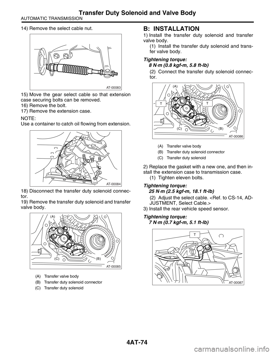
14) Remove the select cable nut.
15) Move the gear select cable so that extension
case securing bolts can be removed.
16) Remove the bolt.
17) Remove the extension case.
NOTE:
Use a container to catch oil flowing from extension.
18) Disconnect the transfer duty solenoid connec-
tor.
19) Remove the transfer duty solenoid and transfer
valve body.B: INSTALLATION
1) Install the transfer duty solenoid and transfer
valve body.
(1) Install the transfer duty solenoid and trans-
fer valve body.
Tightening torque:
8 N
⋅m (0.8 kgf-m, 5.8 ft-lb)
(2) Connect the transfer duty solenoid connec-
tor.
2) Replace the gasket with a new one, and then in-
stall the extension case to transmission case.
(1) Tighten eleven bolts.
Tightening torque:
25 N
⋅m (2.5 kgf-m, 18.1 ft-lb)
(2) Adjust the select cable.
JUSTMENT, Select Cable.>
3) Install the rear vehicle speed sensor.
Tightening torque:
7 N
⋅m (0.7 kgf-m, 5.1 ft-lb)
(A) Transfer valve body
(B) Transfer duty solenoid connector
(C) Transfer duty solenoid
AT-00083
AT-00084
AT-00085
(A)
(C)
(B)
(A) Transfer valve body
(B) Transfer duty solenoid connector
(C) Transfer duty solenoid
AT-00086
(A)
(C)
(B)
TT
AT-00087
T
Page 2403 of 2870
4AT-90
AUTOMATIC TRANSMISSION
Extension Case
29.Extension Case
A: REMOVAL
1) Remove the transmission assembly.
sion Assembly.>
2) Remove the rear vehicle speed sensor.
Non-turbo model
Turbo model
3) Separate the transmission case and extension
case part.
B: INSTALLATION
1) Apply the vaseline to selected thrust needle
bearing and attach it to the end surface of reduction
driven gear.
Transfer Clutch.>
NOTE:
Install the thrust needle bearing in correct direction.
2) Install a new gasket.
3) Install the extension case to transmission case.
4) Tighten bolts to secure the extension case.
Tightening torque:
25 N
⋅m (2.5 kgf-m, 18.1 ft-lb)
5) Install the rear vehicle speed sensor.
Tightening torque:
7 N
⋅m (0.7 kgf-m, 5.1 ft-lb)
Non-turbo model
(A) Rear vehicle speed sensor
(B) Front vehicle speed sensor
(A) Rear vehicle speed sensor
AT-00116
(B)
(A)
AT-01338
(A)
AT-00118
(A) Rear vehicle speed sensor
(B) Front vehicle speed sensor
AT-00118
AT-00116
(B)
(A)
Page 2404 of 2870
4AT-91
AUTOMATIC TRANSMISSION
Extension Case
Turbo model
6) Install the transmission assembly.
Transmission Assembly.>
C: DISASSEMBLY
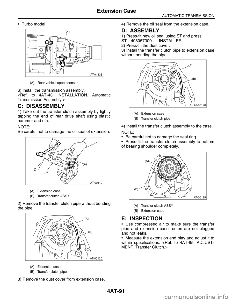
1) Take out the transfer clutch assembly by lightly
tapping the end of rear drive shaft using plastic
hammer and etc.
NOTE:
Be careful not to damage the oil seal of extension.
2) Remove the transfer clutch pipe without bending
the pipe.
3) Remove the dust cover from extension case.4) Remove the oil seal from the extension case.
D: ASSEMBLY
1) Press-fit new oil seal using ST and press.
ST 498057300 INSTALLER
2) Press-fit the dust cover.
3) Install the transfer clutch pipe to extension case
without bending the pipe.
4) Install the transfer clutch assembly to the case.
NOTE:
Be careful not to damage the seal ring.
Press-fit the transfer clutch assembly to bottom
of bearing shoulder completely.
E: INSPECTION
Use compressed air to make sure the transfer
pipe and extension case routes are not clogged
and not leaks.
Measure the extension end play and adjust it to
within specifications.
MENT, Transfer Clutch.>
(A) Rear vehicle speed sensor
(A) Extension case
(B) Transfer clutch ASSY
(A) Extension case
(B) Transfer clutch pipe
AT-01338
(A)
AT-00119
(A)
(B)
AT-00120
(A)
(B)
(A) Extension case
(B) Transfer clutch pipe
(A) Transfer clutch ASSY
(B) Extension case
AT-00120
(A)
(B)
AT-00125
(A)
(B)