Page 2411 of 2870

4AT-97
AUTOMATIC TRANSMISSION
Reduction Driven Gear
31.Reduction Driven Gear
A: REMOVAL
1) Remove the transmission assembly from vehi-
cle.
mission Assembly.>
2) Remove the rear vehicle speed sensor, and then
separate the extension case from transmission
case.
Case.>
3) Set the range select lever to “P” range.
4) Remove the caulking part, and then remove the
lock nut.
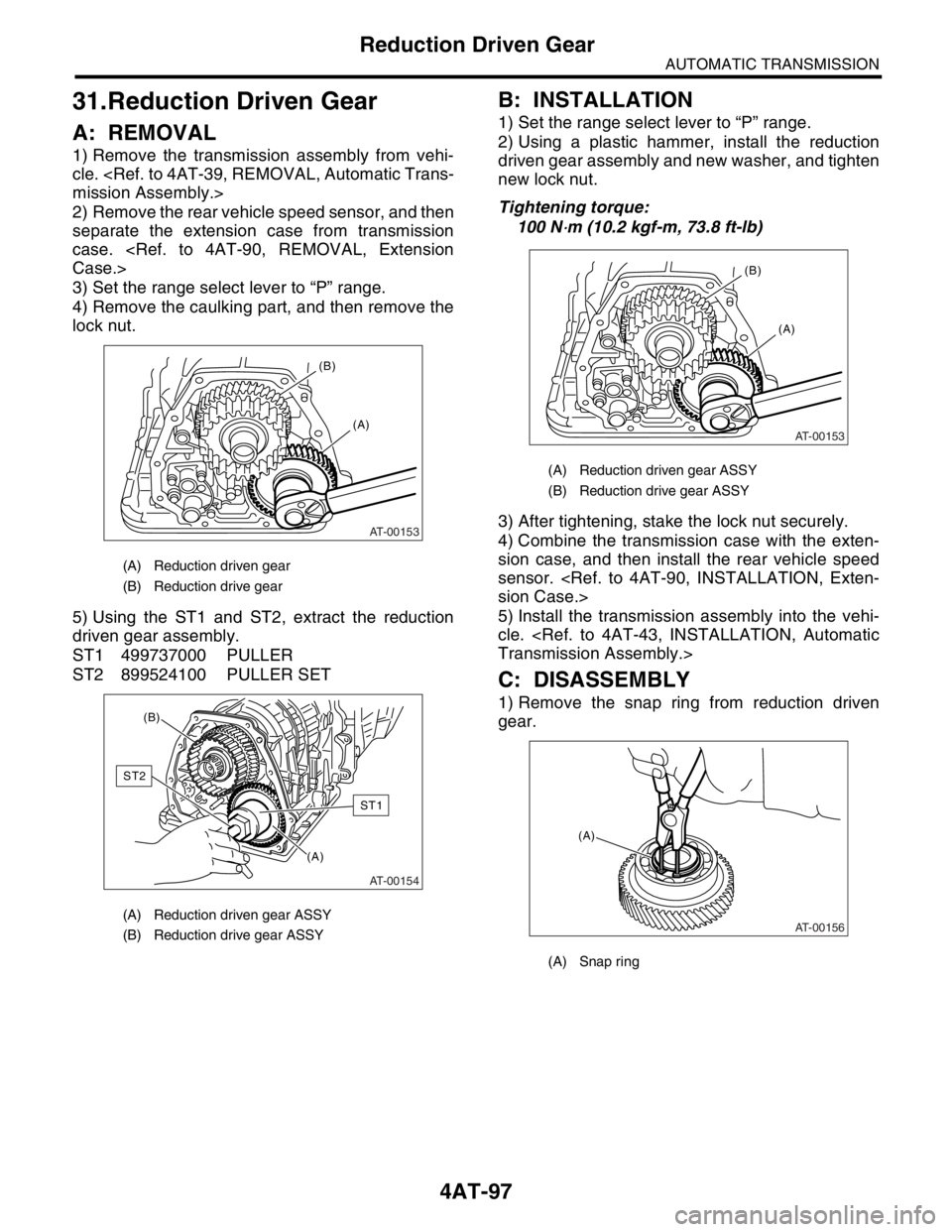
5) Using the ST1 and ST2, extract the reduction
driven gear assembly.
ST1 499737000 PULLER
ST2 899524100 PULLER SET
B: INSTALLATION
1) Set the range select lever to “P” range.
2) Using a plastic hammer, install the reduction
driven gear assembly and new washer, and tighten
new lock nut.
Tightening torque:
100 N
⋅m (10.2 kgf-m, 73.8 ft-lb)
3) After tightening, stake the lock nut securely.
4) Combine the transmission case with the exten-
sion case, and then install the rear vehicle speed
sensor.
sion Case.>
5) Install the transmission assembly into the vehi-
cle.
Transmission Assembly.>
C: DISASSEMBLY
1) Remove the snap ring from reduction driven
gear.
(A) Reduction driven gear
(B) Reduction drive gear
(A) Reduction driven gear ASSY
(B) Reduction drive gear ASSY
AT-00153
(A) (B)
AT-00154
(A) (B)
ST1
ST2
(A) Reduction driven gear ASSY
(B) Reduction drive gear ASSY
(A) Snap ring
AT-00153
(A) (B)
AT-00156
(A)
Page 2413 of 2870

4AT-99
AUTOMATIC TRANSMISSION
Reduction Drive Gear
32.Reduction Drive Gear
A: REMOVAL
1) Remove the transmission assembly from vehi-
cle.
mission Assembly.>
2) Remove the rear vehicle speed sensor, and then
separate the extension case from transmission
case.
Case.>
3) Remove the reduction driven gear.
97, REMOVAL, Reduction Driven Gear.>
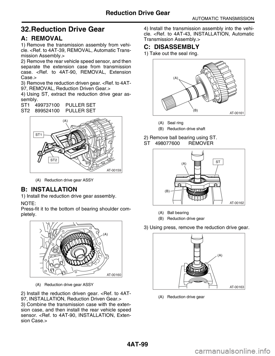
4) Using ST, extract the reduction drive gear as-
sembly.
ST1 499737100 PULLER SET
ST2 899524100 PULLER SET
B: INSTALLATION
1) Install the reduction drive gear assembly.
NOTE:
Press-fit it to the bottom of bearing shoulder com-
pletely.
2) Install the reduction driven gear.
97, INSTALLATION, Reduction Driven Gear.>
3) Combine the transmission case with the exten-
sion case, and then install the rear vehicle speed
sensor.
sion Case.>4) Install the transmission assembly into the vehi-
cle.
Transmission Assembly.>
C: DISASSEMBLY
1) Take out the seal ring.
2) Remove ball bearing using ST.
ST 498077600 REMOVER
3) Using press, remove the reduction drive gear.
(A) Reduction drive gear ASSY
(A) Reduction drive gear ASSY
AT-00159
(A)
ST2
ST1
AT-00160
(A)
(A) Seal ring
(B) Reduction drive shaft
(A) Ball bearing
(B) Reduction drive gear
(A) Reduction drive gear
AT-00161
(A)
(B)
AT-00162
(A)
(B)ST
AT-00163
(A)
Page 2415 of 2870
4AT-101
AUTOMATIC TRANSMISSION
Parking Pawl
33.Parking Pawl
A: REMOVAL
1) Remove the transmission assembly from vehi-
cle.
mission Assembly.>
2) Remove the rear vehicle speed sensor, and then
separate the extension case from transmission
case.
Case.>
3) Remove the reduction drive gear.
99, REMOVAL, Reduction Drive Gear.>
4) Remove the parking pawl, return spring and
shaft.
B: INSTALLATION
1) Install the parking pawl, return spring and shaft.
2) Install the reduction drive gear.
INSTALLATION, Reduction Drive Gear.>
3) Install the extension case and rear vehicle speed
sensor.
sion Case.>
4) Install the transmission assembly into the vehi-
cle.
Transmission Assembly.>
C: INSPECTION
Make sure that the tab of parking pawl on reduction
gear is not worn or otherwise damaged.
(A) Return spring
(B) Parking pawl
(A) Return spring
(B) Parking pawl
AT-00171
(B)(A)
AT-00171
(B)(A)
Page 2464 of 2870

4AT(H4SO)-5
AUTOMATIC TRANSMISSION (DIAGNOSTIC)
General Description
3. General Description
A: CAUTION
Supplemental Restraint System “Airbag”
The airbag system wiring harness is routed near
the transmission control module (TCM).
CAUTION:
All airbag system wiring harness and con-
nectors are colored yellow. Do not use an elec-
trical test equipment on these circuit.
Be careful not to damage the airbag system wir-
ing harness when performing diagnostics and ser-
vicing the TCM.
Measurement
When measuring the voltage and resistance of
ECM, TCM or each sensor, use a tapered pin with
diameter of less than 0.64 mm (0.025 in) in order to
avoid poor contact. Do not insert the pin more than
0.65 mm (0.256 in).
B: INSPECTION
1. BATTERY
Measure the battery voltage and specific gravity of
electrolyte.
Standard voltage: 12 V or more
Specific gravity: Above 1.260
2. TRANSMISSION GROUND
Make sure that the ground terminal bolt is tightened
securely.
Chassis side
Tightening torque:
13 N
⋅m (1.3 kgf-m, 9.4 ft-lb)
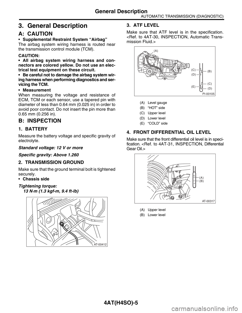
3. ATF LEVEL
Make sure that ATF level is in the specification.
mission Fluid.>
4. FRONT DIFFERENTIAL OIL LEVEL
Make sure that the front differential oil level is in speci-
fication.
Gear Oil.>
AT-00412
(A) Level gauge
(B) “HOT” side
(C) Upper level
(D) Lower level
(E) “COLD” side
(A) Upper level
(B) Lower level
PI-00105
COLD
LFHOT LF
(A)
(C)
(D)
(C)
(D)
(E)
(B)
AT-00317
(A)
(B)
LF
Page 2466 of 2870
4AT(H4SO)-7
AUTOMATIC TRANSMISSION (DIAGNOSTIC)
General Description
C: PREPARATION TOOL
1. SPECIAL TOOL
2. GENERAL TOOL
ILLUSTRATION TOOL NUMBER DESCRIPTION REMARKS
24082AA230
(Newly adopted tool)CARTRIDGE Troubleshooting for electrical systems.
22771AA030 SUBARU SELECT
MONITOR KITTroubleshooting for electrical systems.
English: 22771AA030 (Without printer)
German: 22771AA070 (Without printer)
French: 22771AA080 (Without printer)
Spanish: 22771AA090 (Without printer)
TOOL NAME REMARKS
Circuit tester Used for measuring resistance, voltage and ampere.
Oscilloscope Used for measuring sensor.
ST24082AA230
ST22771AA030
Page 2469 of 2870
4AT(H4SO)-10
AUTOMATIC TRANSMISSION (DIAGNOSTIC)
Electrical Components Location
2. SENSOR
(1) Throttle position sensor (4) Rear vehicle speed sensor (6) ATF temperature sensor
(2) Front vehicle speed sensor (5) Torque converter turbine speed
sensor
(3) Inhibitor switch
AT-00744
(1)
(2)(3)
(4) (5)(6)
AT-00328 (1)
(2)
(4)
AT-00329
(3)
AT-00330
(5)
AT-00331
Page 2472 of 2870

4AT(H4SO)-13
AUTOMATIC TRANSMISSION (DIAGNOSTIC)
Transmission Control Module (TCM) I/O Signal
Inhibitor
switch“2” range
switchB55 6Select lever in “2” range Less than 1
—
Select lever in any other
than “2” rangeMore than 8
“1” range
switchB55 7Select lever in “1” range Less than 1
—
Select lever in any other
than “1” rangeMore than 8
Brake switch B55 12Brake pedal depressed More than 10.5
—
Brake pedal released Less than 1
Kick-down switch B55 11Throttle fully opened Less than 1
—
Throttle fully closed More than 6.5
AT OIL TEMP warning light B56 10Light ON Less than 1
—
Light OFF More than 9
Throttle position sensor B54 3Throttle fully closed 0.2 — 1.0
—
Throttle fully open 4.2 — 4.7
Throttle position sensor
power supplyB54 2Ignition switch ON (with
engine OFF)4.8 — 5.3 —
ATF temperature sensor B54 11ATF temperature 20°C
(68°F)1.6 — 2.0 2.1 k — 2.9 k
ATF temperature 80°C
(176°F)0.4 — 0.9 275 — 375
Rear vehicle speed sensor B55 24Vehicle stopped 0
450 — 650
Vehicle speed at least 20
km/h (12 MPH)More than 1 (AC range)
Front vehicle speed sensor B55 18Vehicle stopped 0
450 — 650
Vehicle speed at least 20
km/h (12 MPH)More than 1 (AC range)
Torque converter turbine
speed sensorB55 8Engine idling after warm-
up (D range)0
450 — 650
Engine idling after warm-
up (N range)More than 1 (AC range)
Vehicle speed output signal B56 17Vehicle speed at most 10
km/h (6 MPH)Less than 1 ←
→ More than 4—
Engine speed signal B55 17Ignition switch ON (with
engine OFF)More than 10.5
—
Ignition switch ON (with
engine ON)8 — 11
Cruise set signal B55 22When cruise control is set
(SET lamp ON)Less than 1
—
When cruise control is not
set (SET lamp OFF)More than 6.5
Torque control signal 1 B56 5Ignition switch ON (with
engine ON)More than 4 —
Torque control signal 2 B56 14Ignition switch ON (with
engine ON)More than 4 —
Torque control cut signal B55 10Ignition switch ON
(After engine is warmed-up)8—
Intake manifold pressure
signalB54 1 Engine idling after warm-up 0.4 — 1.6 —
Shift solenoid 1 B54 221st or 4th gear More than 9
10 — 16
2nd or 3rd gear Less than 1
Shift solenoid 2 B54 51st or 2nd gear More than 9
10 — 16
3rd or 4th gear Less than 1 Check with ignition switch ON.
ContentConnector
No.Terminal No. Measuring conditions Voltage (V)Resistance
to chassis
ground (Ω)
Page 2473 of 2870

4AT(H4SO)-14
AUTOMATIC TRANSMISSION (DIAGNOSTIC)
Transmission Control Module (TCM) I/O Signal
Line pressure duty solenoid B54 9Ignition switch ON (with
engine OFF)
Throttle fully closed after
war m-up1.5 — 4.0
2.0 — 4.5
Ignition switch ON (with
engine OFF)
Throttle fully open after
war m-upLess than 0.5
Lock-up duty solenoid B54 7When lock up occurs More than 8.5
10 — 17
When lock up is released Less than 0.5
Transfer duty solenoid B54 6Fuse on FWD switch Less than 0.5
10 — 17 Fuse removed from FWD
switch (with throttle fully
open and with select lever
in 1st gear)More than 8.5
2-4 brake duty solenoid B54 18Throttle fully closed (with
engine OFF) after warm-up1.5 — 5.0
2.0 — 4.5
Throttle fully open (with
engine OFF) after warm-upLess than 0.5
2-4 brake timing solenoid B54 161st gear Less than 1
10 — 16
3rd gear More than 9
Low clutch timing solenoid B54 152nd gear Less than 1
10 — 16
4th gear More than 9
HOLD switch B55 16HOLD switch ON Less than 1 —
HOLD switch OFF More than 8 —
POWER switch B55 23POWER switch ON Less than 1 —
POWER switch OFF More than 10 —
POWER indicator light B56 11Light ON Less than 1 —
Light OFF More than 9 —
FWD switch B55 20Fuse removed 6 — 9.1 —
Fuse installed Less than 1 —
FWD indicator light B56 2Fused on FWD switch Less than 1 —
Fuse removed from FWD
switchMore than 9 —
ABS signal B55 21ABS switch ON Less than 1 —
ABS switch OFF 6.5 — 15 —
Sensor ground line 1 B54 20 — 0 Less than 1
Sensor ground line 2 B55 9 — 0 Less than 1
System ground lineB56 19
— 0 Less than 1
B54 21
Sensor ground line 3 B54 10 — 0 Less than 1
Sensor ground line 4 B54 19 — 0 Less than 1
AT diagnosis signal B56 21 Ignition switch ONLess than 1 ←
→ More than 4—
Data link signal (Subaru
Select Monitor)B56 15 — — —Check with ignition switch ON.
ContentConnector
No.Terminal No. Measuring conditions Voltage (V)Resistance
to chassis
ground (Ω)