2004 SUBARU FORESTER engine
[x] Cancel search: enginePage 1707 of 2870

EN(H4DOTC)-77
ENGINE (DIAGNOSTIC)
List of Diagnostic Trouble Code (DTC)
P0507 Idle Control System RPM Higher
Than Expected
Code (DTC).>
P0508 Idle Control System Circuit Low
P0509 Idle Control System Circuit High
P0512 Starter Request Circuit
P0513 Incorrect Immobilizer Key
P0519 Idle Control System Malfunction
(Fail-Safe)
Code (DTC).>
P0545 Exhaust Gas Temperature Sensor
Circuit Low - Bank 1
Trouble Code (DTC).>
P0546 Exhaust Gas Temperature Sensor
Circuit High - Bank 1
Code (DTC).>
P0558 Generator Circuit Low Input
P0559 Generator Circuit High Input
P0600 Serial Communication Link
P0604 Internal Control Module Random
Access Memory (RAM) Error
nostic Trouble Code (DTC).>
P0691 Cooling Fan 1 Control Circuit Low
P0692 Cooling Fan 1 Control Circuit High
P0700 Transmission Control System (MIL
Request)
(DTC).>
P0851 Neutral Switch Input Circuit Low
Code (DTC).> or
Diagnostic Trouble Code (DTC).>
P0852 Neutral Switch Input Circuit High
Code (DTC).> or
Diagnostic Trouble Code (DTC).>
P1086 Tumble Generated Valve Position
Sensor 2 Circuit Low
tic Trouble Code (DTC).>
P1087 Tumble Generated Valve Position
Sensor 2 Circuit High
tic Trouble Code (DTC).>
P1088 Tumble Generated Valve Position
Sensor 1 Circuit Low
tic Trouble Code (DTC).> DTC Item NOTE
Page 1708 of 2870

EN(H4DOTC)-78
ENGINE (DIAGNOSTIC)
List of Diagnostic Trouble Code (DTC)
P1089 Tumble Generated Valve Position
Sensor 1 Circuit High
tic Trouble Code (DTC).>
P1090 Tumble Generated Valve System 1
(Valve Open)
Code (DTC).>
P1091 Tumble Generated Valve System 1
(Valve Close)
Code (DTC).>
P1092 Tumble Generated Valve System 2
(Valve Open)
Code (DTC).>
P1093 Tumble Generated Valve System 2
(Valve Close)
Code (DTC).>
P1094 Tumble Generated Valve Signal 1
Circuit Malfunction (Open)
Diagnostic Trouble Code (DTC).>
P1095 Tumble Generated Valve Signal 1
Circuit Malfunction (Short)
Diagnostic Trouble Code (DTC).>
P1096 Tumble Generated Valve Signal 2
Circuit Malfunction (Open)
Diagnostic Trouble Code (DTC).>
P1097 Tumble Generated Valve Signal 2
Circuit Malfunction (Short)
Diagnostic Trouble Code (DTC).>
P1110 Atmospheric Pressure Sensor Cir-
cuit Malfunction (Low Input)
Diagnostic Trouble Code (DTC).>
P1111 Atmospheric Pressure Sensor Cir-
cuit Malfunction (High Input)
Diagnostic Trouble Code (DTC).>
P1152 O
2 Sensor Circuit Range/Perfor-
mance (Low) (Bank 1 Sensor 1)
Diagnostic Trouble Code (DTC).>
P1153 O
2 Sensor Circuit Range/Perfor-
mance (High) (Bank 1 Sensor 1)
Diagnostic Trouble Code (DTC).>
P1301 Misfire Detected (High Tempera-
ture Exhaust Gas)
Code (DTC).>
P1312 Exhaust Gas Temperature Sensor
Malfunction
ble Code (DTC).>
P1518 Starter Switch Circuit Low Input
P1544 Exhaust Gas Temperature Too
High
P1560 Back-Up Voltage Circuit Malfunc-
tion
(DTC).>
P1570 ANTENNA
P1571 Reference Code Incompatibility
Page 1709 of 2870

EN(H4DOTC)-79
ENGINE (DIAGNOSTIC)
List of Diagnostic Trouble Code (DTC)
P1572 IMM Circuit Failure (Except
Antenna Circuit)
P1574 Key Communication Failure
P1576 EGI Control Module EEPROM
P1577 IMM Control Module EEPROM
P2088 OCV Solenoid Valve Signal A Cir-
cuit Open (Bank 1)
Code (DTC).>
P2089 OCV Solenoid Valve Signal A Cir-
cuit Short (Bank 1)
Code (DTC).>
P2092 OCV Solenoid Valve Signal A Cir-
cuit Open (Bank 2)
Code (DTC).>
P2093 OCV Solenoid Valve Signal A Cir-
cuit Short (Bank 2)
Code (DTC).> DTC Item NOTE
Page 1710 of 2870

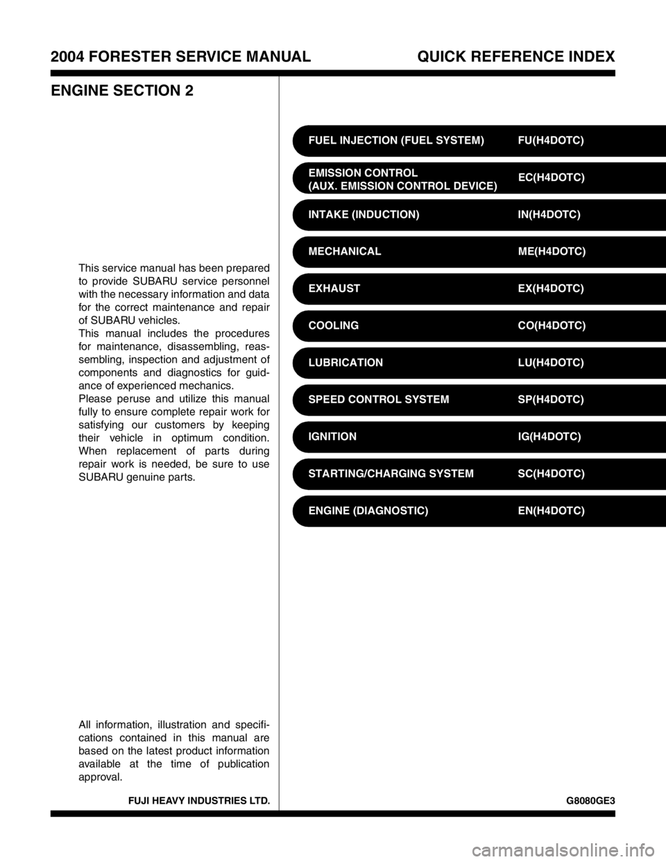
FUJI HEAVY INDUSTRIES LTD. G8080GE3
2004 FORESTER SERVICE MANUAL QUICK REFERENCE INDEX
ENGINE SECTION 2
This service manual has been prepared
to provide SUBARU service personnel
with the necessary information and data
for the correct maintenance and repair
of SUBARU vehicles.
This manual includes the procedures
for maintenance, disassembling, reas-
sembling, inspection and adjustment of
components and diagnostics for guid-
ance of experienced mechanics.
Please peruse and utilize this manual
fully to ensure complete repair work for
satisfying our customers by keeping
their vehicle in optimum condition.
When replacement of parts during
repair work is needed, be sure to use
SUBARU genuine parts.
All information, illustration and specifi-
cations contained in this manual are
based on the latest product information
available at the time of publication
approval.FUEL INJECTION (FUEL SYSTEM) FU(H4DOTC)
EMISSION CONTROL
(AUX. EMISSION CONTROL DEVICE)EC(H4DOTC)
INTAKE (INDUCTION) IN(H4DOTC)
MECHANICAL ME(H4DOTC)
EXHAUST EX(H4DOTC)
COOLING CO(H4DOTC)
LUBRICATION LU(H4DOTC)
SPEED CONTROL SYSTEM SP(H4DOTC)
IGNITION IG(H4DOTC)
STARTING/CHARGING SYSTEM SC(H4DOTC)
ENGINE (DIAGNOSTIC) EN(H4DOTC)
Page 1712 of 2870

ENGINE (DIAGNOSTIC)
EN(H4DOTC)
Page
1. Basic Diagnostics Procedure ......................................................................2
2. Check List for Interview ...............................................................................4
3. General Description ....................................................................................6
4. Electrical Component Location ...................................................................9
5. Engine Control Module (ECM) I/O Signal .................................................23
6. Engine Condition Data ..............................................................................27
7. Transmission Control Module (TCM) I/O Signal .......................................28
8. Data Link Connector .................................................................................29
9. OBD-II General Scan Tool ........................................................................30
10. Subaru Select Monitor...............................................................................33
11. Read Diagnostic Trouble Code (DTC) ......................................................39
12. Inspection Mode ........................................................................................40
13. Drive Cycle ................................................................................................45
14. Clear Memory Mode..................................................................................47
15. Compulsory Valve Operation Check Mode ...............................................48
16. Malfunction Indicator Light ........................................................................50
17. Diagnostics for Engine Starting Failure .....................................................59
18. List of Diagnostic Trouble Code (DTC) .....................................................74
19. Diagnostic Procedure with Diagnostic Trouble Code (DTC) .....................80
20. General Diagnostic Table........................................................................295
Page 1713 of 2870

EN(H4DOTC)-80
ENGINE (DIAGNOSTIC)
Diagnostic Procedure with Diagnostic Trouble Code (DTC)
19.Diagnostic Procedure with Diagnostic Trouble Code (DTC)
A: DTC P0011 “A” CAMSHAFT POSITION - TIMING OVER - ADVANCED OR
SYSTEM PERFORMANCE (BANK 1)
DTC DETECTING CONDITION:
Detect as soon as the malfunction occurs.
TROUBLE SYMPTOM:
Engine stalls.
Erroneous idling
CAUTION:
After repair or replacement of faulty parts, conduct Clear Memory Mode
Step Check Yes No
1 CHECK DTC ON DISPLAY.Is any other DTC displayed? Inspect the rele-
vant DTC using
“List of Diagnostic
Trouble Code
(DTC)”.
List of Diagnostic
Trouble Code
(DTC).>Go to step 2.
2 CHECK CURRENT DATA.
1) Start the engine and idle it.
2) Check the AVCS system operating angle
and oil flow control solenoid valve duty output
using Subaru Select Monitor or OBD-II general
scan tool.
N
OTE:
Subaru Select Monitor
For detailed operation procedure, refer to
“READ CURRENT DATA SHOWN ON DIS-
PLAY FOR ENGINE”.
OBD-II general scan tool
For detailed operation procedures, refer to the
OBD-II General Scan Tool Operation Manual.Is the AVCS system operating
angle approx. 0 degree and oil
flow control solenoid valve duty
output approx. 10%?A temporary poor
malfunction. Per-
for m the following
to clean oil routing.
Replace the
engine oil, and
then idle the
engine for 5 min-
utes and replace
the oil filter and
engine oil.Check the follow-
ing and repair or
replace it if neces-
sary.
Oil pipe (clog-
ging)
Oil flow con-
trol solenoid
valve (clogging
or dirt of oil
routing, spring
setting, clog-
ging of valve)
Intake cam-
shaft (dirt, dam-
age of
camshaft)
Timing belt
(alignment of
timing mark)
Page 1714 of 2870

EN(H4DOTC)-81
ENGINE (DIAGNOSTIC)
Diagnostic Procedure with Diagnostic Trouble Code (DTC)
B: DTC P0021 “A” CAMSHAFT POSITION - TIMING OVER - ADVANCED OR
SYSTEM PERFORMANCE (BANK 2)
DTC DETECTING CONDITION:
Detect as soon as the malfunction occurs.
TROUBLE SYMPTOM:
Engine stalls.
Erroneous idling
CAUTION:
After repair or replacement of faulty parts, conduct Clear Memory Mode
Step Check Yes No
1 CHECK DTC ON DISPLAY.Is any other DTC displayed? Inspect the rele-
vant DTC using
“List of Diagnostic
Trouble Code
(DTC)”.
List of Diagnostic
Trouble Code
(DTC).>Go to step 2.
2 CHECK CURRENT DATA.
1) Start the engine and idle it.
2) Check the AVCS system operating angle
and oil flow control solenoid valve duty output
using Subaru Select Monitor or OBD-II general
scan tool.
NOTE:
Subaru Select Monitor
For detailed operation procedure, refer to
“READ CURRENT DATA SHOWN ON DIS-
PLAY FOR ENGINE”.
OBD-II general scan tool
For detailed operation procedures, refer to the
OBD-II General Scan Tool Operation Manual.Is the AVCS system operating
angle approx. 0 degree and oil
flow control solenoid valve duty
output approx. 10%?A temporary poor
malfunction. Per-
for m the following
to clean oil routing.
Replace the
engine oil, and
then idle the
engine for 5 min-
utes and replace
the oil filter and
engine oil.Check the follow-
ing and repair or
replace it if neces-
sary.
Engine oil
(amount, dirt)
Oil pipe (clog-
ging)
Oil flow con-
trol solenoid
valve (clogging
or dirt of oil
routing, spring
setting, clog-
ging of valve)
Intake cam-
shaft (dirt, dam-
age of
camshaft)
Timing belt
(alignment of
timing mark)
Page 1715 of 2870

EN(H4DOTC)-82
ENGINE (DIAGNOSTIC)
Diagnostic Procedure with Diagnostic Trouble Code (DTC)
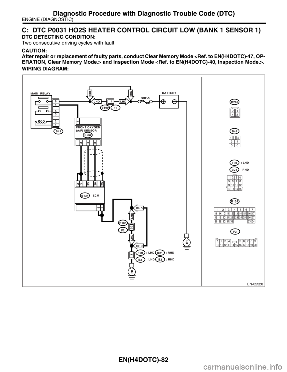
C: DTC P0031 HO2S HEATER CONTROL CIRCUIT LOW (BANK 1 SENSOR 1)
DTC DETECTING CONDITION:
Two consecutive driving cycles with fault
CAUTION:
After repair or replacement of faulty parts, conduct Clear Memory Mode
WIRING DIAGRAM:
EN-02320
BATTERYMAIN RELAYSBF-5
B47 1 2 3 5 4 6
E
E
B100F2
14LHD
RHD
LHD
RHD
B100
F2
F60
E3
20
3
RHD
RHD6
72
3
33
26
25
ECMB134
: LHD: LHD
B21: RHD: RHD
1
4 2
3
B262
FRONT OXYGEN
(A/F) SENSOR
3412
56
123
4
56
78
9
1011 12
1314 15 16
B21
F60
B47
B262
B134
F2
LHD LHD
1234
56 7
82 1
94 310
24 22 23 25 11 12 13 14 15
26 27
2816 17
18 19 20 21
33 34 29
32 30 31
1234 5678910 11 12 13 14 15 16 17 18 19 20
: LHDE2: RHD