2004 SUBARU FORESTER relay
[x] Cancel search: relayPage 597 of 2870

CC(H4SO)-29
CRUISE CONTROL SYSTEM (DIAGNOSTIC)
Diagnostic Procedure with Diagnostic Trouble Code (DTC)
8. Diagnostic Procedure with
Diagnostic Trouble Code
(DTC)
A: DTC 21, 24, 25 AND 2A CRUISE
CONTROL MODULE BUILT-IN RE-
LAY, CPU RAM
DIAGNOSIS:
Poor welding of built-in relay of cruise control mod-
ule.
Failure of built-in CPU RAM of cruise control mod-
ule.
TROUBLE SYMPTOM:
Cruise control is canceled and memorized cruise
speed is also canceled.
Once cruise control is canceled, cruise control
cannot be set until the ignition switch and cruise
control main switch turns OFF, and then turns ON
again.
NOTE:
Check input/output signal and vehicle speed signal
with select monitor. When signals are in good con-
dition, failure is in cruise control module. (Check
the power supply and ground conditions of cruise
control module.)
Page 598 of 2870

CC(H4SO)-30
CRUISE CONTROL SYSTEM (DIAGNOSTIC)
Diagnostic Procedure with Diagnostic Trouble Code (DTC)
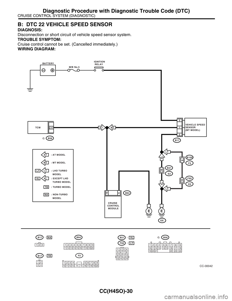
B: DTC 22 VEHICLE SPEED SENSOR
DIAGNOSIS:
Disconnection or short circuit of vehicle speed sensor system.
TROUBLE SYMPTOM:
Cruise control cannot be set. (Cancelled immediately.)
WIRING DIAGRAM:
CC-00042
BATTERY
CRUISE
CONTROL
MODULE
M/B No.5IGNITION
RELAY
B17 TCM
E
C17
B17
B21
B94E2
B56
B56 C:
GEVEHICLE SPEED
SENSOR
(MT MODEL) 1
2
3
619
B94
E
16
MT
AT : AT MODEL C:
MT : MT MODELAT
12312345678910
11 12 13 14 15 16 17 18 19 20
123
4
56
78
9
1011 12
1314 15 16
12
789 56 3410 11 12
19 20 2113 14 15 16 17 18
22
23
24
F60
E216
B100
F29
LT
LT
XLXL
LT : LHD TURBO
MODEL
XL : EXCEPT LHD
TURBO MODEL
: TURBO MODEL
: NON-TURBO
MODELXL
LT
TB
NA
B17
3412
F2
1234 5678910 11 12 13 14 15 16 17 18 19 20
NA
TB :
:
F60LT :
B21XL :
Page 599 of 2870

CC(H4SO)-31
CRUISE CONTROL SYSTEM (DIAGNOSTIC)
Diagnostic Procedure with Diagnostic Trouble Code (DTC)
Step Check Yes No
1 CHECK TRANSMISSION TYPE.Is the target MT model? Go to step 2.Go to step 6.
2 CHECK HARNESS BETWEEN BATTERY
AND VEHICLE SPEED SENSOR.
1) Turn the ignition switch to OFF.
2) Disconnect the harness connector from
vehicle speed sensor.
3) Turn the ignition switch to ON.
4) Measure the voltage between vehicle
speed sensor harness connector terminal and
chassis ground.
Connector & terminal
(B17) No. 3 (+) — Chassis ground (
−):Is the voltage more than 10 V? Go to step 3.Check the harness
for open or short
between fuse relay
and vehicle speed
sensor.
3 CHECK HARNESS BETWEEN CRUISE CON-
TROL MODULE AND VEHICLE SPEED SEN-
SOR.
1) Turn the ignition switch to OFF.
2) Disconnect the harness connector from
cruise control module.
3) Measure the resistance between vehicle
speed sensor harness connector terminal and
cruise control module harness connector ter-
minal.
Connector & terminal
(B17) No. 1 — (B94) No. 19:Is the resistance less than 10
Ω?Go to step 4.Repair the har-
ness.
4 CHECK HARNESS BETWEEN VEHICLE
SPEED SENSOR AND ENGINE GROUND.
1) Turn the ignition switch to OFF.
2) Measure the resistance between vehicle
speed sensor harness connector terminal and
engine ground.
Connector & terminal
(B17) No. 2 — Engine ground:Is the resistance less than 10
Ω?Go to step 5.Repair the har-
ness.
5 CHECK VEHICLE SPEED SENSOR.
1) Connect the harness connector to vehicle
speed sensor.
2) Lift-up the vehicle and support with rigid
racks.
3) Drive the vehicle at speed greater than 20
km/h (12 MPH).
Warning:
Be careful not to be caught up by the run-
ning wheels.
4) Measure the voltage between cruise control
module harness connector terminal and chas-
sis ground.
Connector & terminal
(B94) No. 19 (+) — Chassis ground (
−):Is the voltage less than 0 V ←
→ more than 5 V?Replace the cruise
control module.
Module.>Replace the vehi-
cle speed sensor.
6 CHECK HARNESS BETWEEN CRUISE CON-
TROL MODULE AND TCM.
1) Turn the ignition switch to OFF.
2) Disconnect the harness connector from
TCM and cruise control module.
3) Measure the resistance between cruise
control module harness connector terminal
and TCM harness connector terminal.
Connector & terminal
(B94) No. 19 — (B56) No. 17:Is the resistance less than 10
Ω?Go to step 7.Repair the har-
ness.
Page 624 of 2870

CC(H4DOTC 2.5)-12
CRUISE CONTROL SYSTEM (DIAGNOSTIC)
Diagnostic Procedure with Symptom
Step Check Yes No
1 CHECK CRUISE INDICATOR LIGHT CIR-
CUIT.
1) Turn the ignition switch to OFF.
2) Disconnect the combination meter harness
connector.
3) Turn the ignition switch to ON.
4) Measure the voltage between harness con-
nector terminal and chassis ground.
Connector & terminal
(i10) No. 9 (+) — Chassis ground (
−):Is the voltage more than 10 V? Go to step 2. Check the fuse
No. 14 (in fuse &
relay box).
Check the har-
ness for open or
short between
combination meter
and fuse & relay
box.
2 CHECK CRUISE INDICATOR LIGHT CIR-
CUIT.
1) Turn the ignition switch to OFF.
2) Disconnect the ECM harness connector.
3) Measure the resistance between ECM har-
ness connector terminal and combination
meter harness connector terminal.
Connector & terminal
(B134) No. 15 — (i10) No. 16:Is the resistance less than 10
Ω?Go to step 3.Repair the har-
ness.
3 CHECK CRUISE INDICATOR LIGHT CIR-
CUIT.
Ground the ECM harness connector terminal
with a suitable wire.
Connector & terminal
(B134) No. 15 — Chassis ground:Does the cruise indicator light
illuminate?Check the poor
contact of ECM
connector.Replace the meter
main assembly.
Page 628 of 2870

CC(H4DOTC 2.5)-16
CRUISE CONTROL SYSTEM (DIAGNOSTIC)
Diagnostic Procedure with Diagnostic Trouble Code (DTC)
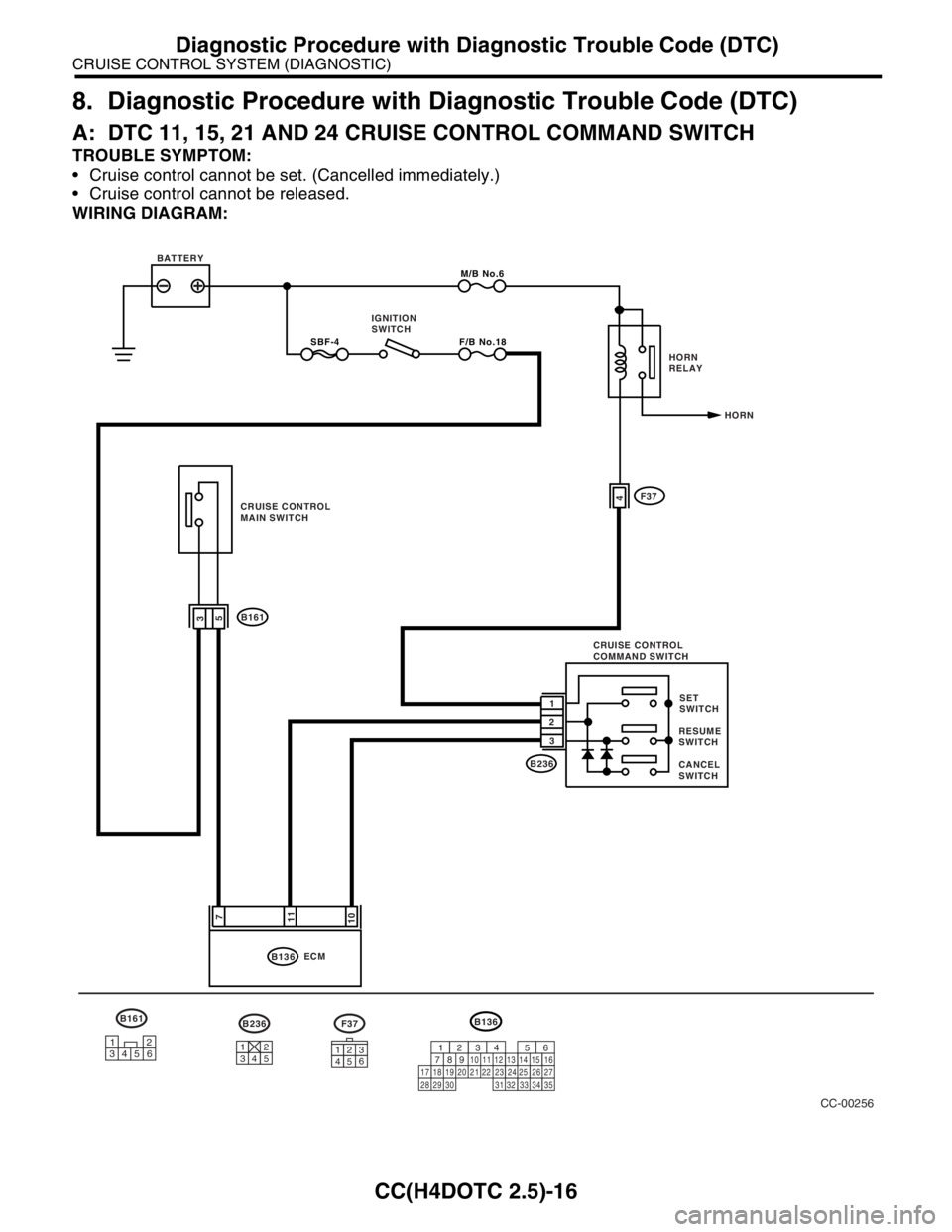
8. Diagnostic Procedure with Diagnostic Trouble Code (DTC)
A: DTC 11, 15, 21 AND 24 CRUISE CONTROL COMMAND SWITCH
TROUBLE SYMPTOM:
Cruise control cannot be set. (Cancelled immediately.)
Cruise control cannot be released.
WIRING DIAGRAM:
CC-00256
F37B236
31264531245
B136
9
30 29 28 323120 19 18 22211012
1114
24
34 3327
261612345613
2315
25871735
B136M/B No.6
10113
B2361SET
SWITCH
CANCEL
SWITCHRESUME
SWITCH SBF-4F/B No.18
7
ECM BATTERY
HORN IGNITION
SWITCH
5
CRUISE CONTROL
MAIN SWITCH4
B161
2
3CRUISE CONTROL
COMMAND SWITCHF37HORN
RELAY
B161
12
3456
Page 629 of 2870

CC(H4DOTC 2.5)-17
CRUISE CONTROL SYSTEM (DIAGNOSTIC)
Diagnostic Procedure with Diagnostic Trouble Code (DTC)
Step Check Yes No
1 CHECK CRUISE CONTROL MAIN SWITCH
CIRCUIT.
1) Turn the ignition switch to OFF.
2) Disconnect the ECM harness connector.
3) Turn the ignition switch to ON.
4) Measure the voltage between harness con-
nector terminal and chassis ground when the
main switch is pressed and is not pressed.
Connector & terminal
(B136) No. 7 (+) — Chassis ground (
−):Is the voltage 0 V when the
main switch is not pressed? Is
the voltage more than 10 V
when the main switch is
pressed?Go to step 2. Check the fuse
No. 18 (in fuse &
relay box).
Check the har-
ness for open or
short between
cruise control
command switch
and fuse & relay
box. If no malfunc-
tion is found after
checking above,
Go to step 6.
2 CHECK SET/COAST SWITCH CIRCUIT.
1) Turn the ignition switch to OFF.
2) Disconnect the ECM harness connector.
3) Measure the voltage between harness con-
nector terminal and chassis ground when SET/
COAST switch is pressed and not pressed.
Connector & terminal
(B136) No. 11 (+) — Chassis ground (
−):Is the voltage 0 V when SET/
COAST switch is not pressed?
Is the voltage more than 10 V
when SET/COAST switch is
pressed?Go to step 3.Go to step 5.
3 CHECK RESUME/ACCEL SWITCH CIRCUIT.
Measure the voltage between harness connec-
tor terminal and chassis ground when
RESUME/ACCEL switch is pressed and not
pressed.
Connector & terminal
(B136) No. 10 (+) — Chassis ground (
−):Is the voltage 0 V when
RESUME/ACCEL switch is not
pressed? Is the voltage more
than 10 V when RESUME/
ACCEL switch is pressed?Go to step 4.Go to step 5.
4 CHECK CANCEL SWITCH CIRCUIT.
Measure the voltage between harness connec-
tor terminal and chassis ground when CAN-
CEL switch is pressed and not pressed.
Connector & terminal
(B136) No. 10 (+) — Chassis ground (
−):
(B136) No. 11 (+) — Chassis ground (
−): Is the voltage 0 V when CAN-
CEL switch is not pressed? Is
the voltage more than 10 V
when CANCEL switch is
pressed?Cruise control
command switch
circuit is OK.Go to step 5.
5 CHECK POWER SUPPLY FOR COMMAND
SWITCH.
Check the horn operation.Does the horn sound? Go to step 6. Check the fuse
No. 6 (in main fuse
box).
Check the horn
relay.
RELAY, INSPEC-
TION, Horn Sys-
tem.>
Check the har-
ness for open or
short between
cruise control
command switch
and fuse & relay
box.
6 CHECK CRUISE CONTROL COMMAND
SWITCH.
Remove and check the cruise control com-
mand switch.
switch OK?Check the harness
between cruise
control command
switch and ECM.Replace the cruise
control command
switch.
Page 631 of 2870

CC(H4DOTC 2.5)-19
CRUISE CONTROL SYSTEM (DIAGNOSTIC)
Diagnostic Procedure with Diagnostic Trouble Code (DTC)
Step Check Yes No
1 CHECK STOP LIGHT SWITCH AND BRAKE
SWITCH CIRCUIT.
1) Turn the ignition switch to OFF.
2) Disconnect the stop light switch and brake
switch harness connector.
3) Turn the ignition switch to ON.
4) Measure the voltage between harness con-
nector terminal and chassis ground.
Connector & terminal
(B65) No. 2 (+) — Chassis ground (
−): Is the voltage more than 10 V? Go to step 2. Check the fuse
No. 16 (in fuse &
relay box).
Check the har-
ness for open or
short between
stop light/brake
switch and fuse &
relay box.
2 CHECK STOP LIGHT SWITCH AND BRAKE
SWITCH CIRCUIT.
Measure the voltage between harness connec-
tor terminal and chassis ground.
Connector & terminal
(B65) No. 1 (+) — Chassis ground (
−): Is the voltage more than 10 V? Go to step 3. Check the fuse
No. 11 (in fuse &
relay box).
Check the har-
ness for open or
short between
stop light/brake
switch and fuse &
relay box.
Check the clutch
switch and circuit.
3 CHECK STOP LIGHT SWITCH AND BRAKE
SWITCH CIRCUIT.
1) Turn the ignition switch to OFF.
2) Disconnect the ECM harness connector.
3) Measure the resistance between ECM har-
ness connector terminal and stop light switch
and brake switch harness connector terminal.
Connector & terminal
(B136) No. 8 — (B65) No. 3:
(B136) No. 9 — (B65) No. 4: Is the resistance less than 10
Ω? Go to step 4.Repair the har-
ness.
4 CHECK STOP LIGHT SWITCH AND BRAKE
SWITCH.
Remove and check the stop light switch and
brake switch.
brake switch OK? Stop light switch
and brake switch
circuit are OK.Replace the stop
light switch and
brake switch.
Page 633 of 2870

CC(H4DOTC 2.5)-21
CRUISE CONTROL SYSTEM (DIAGNOSTIC)
Diagnostic Procedure with Diagnostic Trouble Code (DTC)
Step Check Yes No
1 CHECK CLUTCH SWITCH CIRCUIT.
1) Turn the ignition switch to OFF.
2) Disconnect the clutch switch harness con-
nector.
3) Turn the ignition switch to ON.
4) Measure the voltage between harness con-
nector terminal and chassis ground.
Connector & terminal
(B107) No. 2 (+) — Chassis ground (
−):Is the voltage more than 10 V? Go to step 2. Check the fuse
No. 11 (fuse &
relay box).
Check the har-
ness for open or
short between
clutch switch and
fuse & relay box.
2 CHECK CLUTCH SWITCH CIRCUIT.
1) Turn the ignition switch to OFF.
2) Disconnect the ECM harness connector.
3) Measure the resistance between clutch
switch harness connector terminal and ECM
harness connector terminal.
Connector & terminal
(B107) No. 1 — (B134) No. 1:Is the resistance less than 10
Ω? Go to step 3.Repair the har-
ness.
3 CHECK CLUTCH SWITCH.
Remove and check the clutch switch.
cuit is OK.Replace the clutch
switch.