2004 SUBARU FORESTER relay
[x] Cancel search: relayPage 835 of 2870

FU(H4SO)-53
FUEL INJECTION (FUEL SYSTEM)
Fuel Filler Pipe
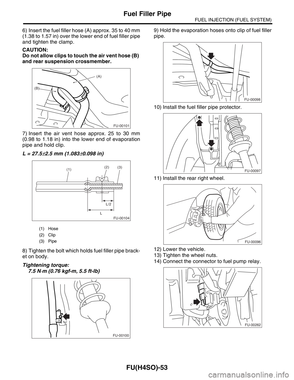
6) Insert the fuel filler hose (A) approx. 35 to 40 mm
(1.38 to 1.57 in) over the lower end of fuel filler pipe
and tighten the clamp.
CAUTION:
Do not allow clips to touch the air vent hose (B)
and rear suspension crossmember.
7) Insert the air vent hose approx. 25 to 30 mm
(0.98 to 1.18 in) into the lower end of evaporation
pipe and hold clip.
L = 27.5
±2.5 mm (1.083±0.098 in)
8) Tighten the bolt which holds fuel filler pipe brack-
et on body.
Tightening torque:
7.5 N
⋅m (0.76 kgf-m, 5.5 ft-lb)9) Hold the evaporation hoses onto clip of fuel filler
pipe.
10) Install the fuel filler pipe protector.
11) Install the rear right wheel.
12) Lower the vehicle.
13) Tighten the wheel nuts.
14) Connect the connector to fuel pump relay.
(1) Hose
(2) Clip
(3) Pipe
(A)
(B)
FU-00101
FU-00104
(1)(2)
L/2
L(3)
FU-00100
FU-00098
FU-00097
FU-00096
FU-00262
Page 899 of 2870

ME(H4SO)-30
MECHANICAL
Fuel Pressure
7. Fuel Pressure
A: INSPECTION
WARNING:
Before removing the fuel pressure gauge, re-
lease the fuel pressure.
NOTE:
If out of specification, check or replace the pressure
regulator and pressure regulator vacuum hose.
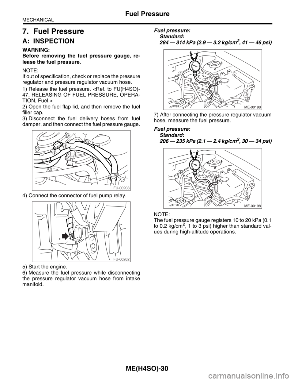
1) Release the fuel pressure.
TION, Fuel.>
2) Open the fuel flap lid, and then remove the fuel
filler cap.
3) Disconnect the fuel delivery hoses from fuel
damper, and then connect the fuel pressure gauge.
4) Connect the connector of fuel pump relay.
5) Start the engine.
6) Measure the fuel pressure while disconnecting
the pressure regulator vacuum hose from intake
manifold.Fuel pressure:
Standard:
284 — 314 kPa (2.9 — 3.2 kg/cm
2, 41 — 46 psi)
7) After connecting the pressure regulator vacuum
hose, measure the fuel pressure.
Fuel pressure:
Standard:
206 — 235 kPa (2.1 — 2.4 kg/cm
2, 30 — 34 psi)
NOTE:
The fuel pressure gauge registers 10 to 20 kPa (0.1
to 0.2 kg/cm
2, 1 to 3 psi) higher than standard val-
ues during high-altitude operations.
FU-00208
FU-00262
ME-00198
ME-00198
Page 962 of 2870

ME(H4SO)-91
MECHANICAL
Engine Trouble in General
22.Engine Trouble in General
A: INSPECTION
NOTE:
“RANK” shown in the chart refer to the possibility of reason for the trouble in order (“Very often” to “Rarely”)
A — Very often
B — Sometimes
C — Rarely
TROUBLE PROBLEM PARTS, ETC. POSSIBLE CAUSE RANK
1. Engine will not start.
1) Starter does not turn. Starter Defective battery-to-starter harness B
Defective starter switch C
Defective inhibitor switch or neutral switch C
Defective starter B
Battery Poor terminal connection A
Run-down battery A
Defective charging system B
Friction Seizure of crankshaft and connecting rod bearing C
Seized camshaft C
Seized or stuck piston and cylinder C
2) Initial combustion does
not occur. Starter Defective starter C
Engine control system
Fuel line Defective fuel pump and relay A
Lack of or insufficient fuel B
Belt Defective B
Defective timing B
Compression Incorrect valve clearance C
Loosened spark plugs or defective gasket C
Loosened cylinder head bolts or defective gasket C
Improper valve seating C
Defective valve stem C
Worn or broken valve spring B
Worn or stuck piston rings, cylinder and piston C
Incorrect valve timing B
Improper engine oil (low viscosity) B
3) Initial combustion occurs. Engine control system
Intake system Defective intake manifold gasket B
Defective throttle body gasket B
Fuel line Defective fuel pump and relay C
Clogged fuel line C
Lack of or insufficient fuel B
Belt Defective B
Defective timing B
Compression Incorrect valve clearance C
Loosened spark plugs or defective gasket C
Loosened cylinder head bolts or defective gasket C
Improper valve seating C
Defective valve stem C
Worn or broken valve spring B
Worn or stuck piston rings, cylinder and piston C
Incorrect valve timing B
Improper engine oil (low viscosity) B
Page 963 of 2870

ME(H4SO)-92
MECHANICAL
Engine Trouble in General
4) Engine stalls after initial
combustion. Engine control system
Intake system Loosened or cracked intake duct B
Loosened or cracked PCV hose C
Loosened or cracked vacuum hose C
Defective intake manifold gasket B
Defective throttle body gasket B
Dirty air cleaner element C
Fuel line Clogged fuel line C
Lack of or insufficient fuel B
Belt Defective B
Defective timing B
Compression Incorrect valve clearance C
Loosened spark plugs or defective gasket C
Loosened cylinder head bolts or defective gasket C
Improper valve seating C
Defective valve stem C
Worn or broken valve spring B
Worn or stuck piston rings, cylinder and piston C
Incorrect valve timing B
Improper engine oil (low viscosity) B
2. Rough idle and engine
stallEngine control system
Intake system Loosened or cracked intake duct A
Loosened or cracked PCV hose A
Loosened or cracked vacuum hose A
Defective intake manifold gasket B
Defective throttle body gasket B
Defective PCV valve C
Loosened oil filler cap B
Dirty air cleaner element C
Fuel line Defective fuel pump and relay C
Clogged fuel line C
Lack of or insufficient fuel B
Belt Defective timing C
Compression Incorrect valve clearance B
Loosened spark plugs or defective gasket B
Loosened cylinder head bolts or defective gasket B
Improper valve seating B
Defective valve stem C
Worn or broken valve spring B
Worn or stuck piston rings, cylinder and piston B
Incorrect valve timing A
Improper engine oil (low viscosity) B
Lubrication system Incorrect oil pressure B
Defective rocker cover gasket C
Cooling system Overheating C
Others Malfunction of evaporative emission control system A
Stuck or damaged throttle valve B
Accelerator cable out of adjustment C TROUBLE PROBLEM PARTS, ETC. POSSIBLE CAUSE RANK
Page 964 of 2870

ME(H4SO)-93
MECHANICAL
Engine Trouble in General
3. Low output, hesitation and
poor accelerationEngine control system
Intake system Loosened or cracked intake duct A
Loosened or cracked PCV hose A
Loosened or cracked vacuum hose B
Defective intake manifold gasket B
Defective throttle body gasket B
Defective PCV valve B
Loosened oil filler cap B
Dirty air cleaner element A
Fuel line Defective fuel pump and relay B
Clogged fuel line B
Lack of or insufficient fuel C
Belt Defective timing B
Compression Incorrect valve clearance B
Loosened spark plugs or defective gasket B
Loosened cylinder head bolts or defective gasket B
Improper valve seating B
Defective valve stem C
Worn or broken valve spring B
Worn or stuck piston rings, cylinder and piston C
Incorrect valve timing A
Improper engine oil (low viscosity) B
Lubrication system Incorrect oil pressure B
Cooling system Overheating C
Over cooling C
Others Malfunction of evaporative emission control system A
4. Surging Engine control system
Intake system Loosened or cracked intake duct A
Loosened or cracked PCV hose A
Loosened or cracked vacuum hose A
Defective intake manifold gasket B
Defective throttle body gasket B
Defective PCV valve B
Loosened oil filler cap B
Dirty air cleaner element B
Fuel line Defective fuel pump and relay B
Clogged fuel line B
Lack of or insufficient fuel C
Belt Defective timing B
Compression Incorrect valve clearance B
Loosened spark plugs or defective gasket C
Loosened cylinder head bolts or defective gasket C
Improper valve seating C
Defective valve stem C
Worn or broken valve spring C
Worn or stuck piston rings, cylinder and piston C
Incorrect valve timing A
Improper engine oil (low viscosity) B
Cooling system Overheating B
Others Malfunction of evaporative emission control system C TROUBLE PROBLEM PARTS, ETC. POSSIBLE CAUSE RANK
Page 996 of 2870

CO(H4SO)-13
COOLING
Radiator Fan System
2. Radiator Fan System
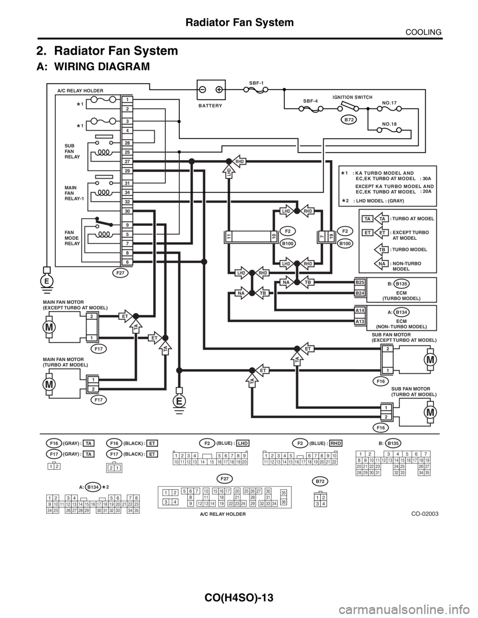
A: WIRING DIAGRAM
CO-02003
B72 SBF-1
SBF-4
NO.17
NO.18
MAIN FAN MOTOR
(EXCEPT TURBO AT MODEL)
F17
2
1
ET
MAIN
FA N
RELAY-1
FA N
MODE
RELAY31
34
32
30
5
9
7
8
6 SUB
FA N
RELAY A/C RELAY HOLDER
28
25
3
4
27
29
RHD
RHD
RHD
RHDLHD
LHD
LHD
F2
B1001110F2
B100197
2
1
F27
B25
B24
A14
ECM
(NON- TURBO MODEL)B134 A:
A13
NA
F17
F16
21
LHD
RHD
F2(BLACK)
(BLACK) (GRAY)
(GRAY)F2
A/C RELAY HOLDER
F27
12
34
567891110
1312142120
2322243130
333234
1615171819
26252728293536
B:B135
A:
B134
1234567891011121314151617181920212223242526272829303132333435
: : ::
ET
TA
1234 5678910 11 12 13 14 15 16 17 18 19 2012345
678910
11 12 19 20 2113 14 15 16 17 18 22
B135 B:
ECM
(TURBO MODEL)
(BLUE)
(BLUE)
567 2 134
2910
1112131415252416
30
98171819202821222332312627333435
: TURBO MODELTB
: NON-TURBO
MODEL
NA: TURBO AT MODEL
TA
: EXCEPT TURBO
AT MODEL
ET
: KA TURBO MODEL AND
EC,EK TURBO AT MODEL : 30A 1*
1*
1*
: LHD MODEL : (GRAY) 2*
2*
SUB FAN MOTOR
(TURBO AT MODEL)
F16
1
2
MAIN FAN MOTOR
(TURBO AT MODEL)
F17
1
2
SUB FAN MOTOR
(EXCEPT TURBO AT MODEL)
F16
2
1
TA
ET
TA
TA
LHD
TA
ET
ET
TBNA
TB
12
F17
F16TA
:
TA
ET
:
ET
E
EXCEPT KA TURBO MODEL AND
EC,EK TURBO AT MODEL: 20A
IGNITION SWITCH
BATTERY
3412
B72
Page 997 of 2870

CO(H4SO)-14
COOLING
Radiator Fan System
B: INSPECTION
DETECTING CONDITION:
Engine coolant temperature is above 95°C (203°F).
Vehicle speed is below 19 km/h (12 MPH).
TROUBLE SYMPTOM:
Radiator main fan and sub fan does not rotate under the above conditions.
Step Check Yes No
1 CHECK OPERATION OF RADIATOR FAN.
1) Connect the test mode connector.
2) Turn the ignition switch to ON.
3) Using Subaru Select Monitor, check the
compulsory operation of radiator fan relay.
N
OTE:
With Subaru Select Monitor
When checking the compulsory operation of
radiator fan, the radiator main and sub fan
repeat the rotation in order of following: low
speed rotation → high speed rotation → off.
Subaru Select Monitor
Refer to Compulsory Valve Operation Check
Mode for detail procedures.
Check Mode.>Do the radiator main and sub
fan rotate at low speed?Go to step 2.Go to step 3.
2 CHECK OPERATION OF RADIATOR FAN.
1) Connect the test mode connector.
2) Turn the ignition switch to ON.
3) Using Subaru Select Monitor, check the
compulsory operation of radiator fan relay.
N
OTE:
With Subaru Select Monitor
When checking the compulsory operation of
radiator fan, the radiator main and sub fan
repeat the rotation in order of following: low
speed rotation → high speed rotation → off.
Subaru Select Monitor
Refer to Compulsory Valve Operation Check
Mode for detail procedures.
Check Mode.>Do the radiator main and sub
fan rotate at high speed?Radiator main fan
system is okay.Go to step 32.
3 CHECK POWER SUPPLY TO MAIN FAN RE-
LAY.
1) Turn the ignition switch to OFF.
2) Remove the fan relay 1 from A/C relay
holder.
3) Measure the voltage between main fan
relay terminal and chassis ground.
Connector & terminal
(F27) No. 31 (+) — Chassis ground (
−):Is the voltage more than 10 V? Go to step 4.Go to step 5.
4 CHECK POWER SUPPLY TO MAIN FAN RE-
LAY.
1) Turn the ignition switch to ON.
2) Measure the voltage between main fan
relay terminal and chassis ground.
Connector & terminal
(F27) No. 34 (+) — Chassis ground (
−):Is the voltage more than 10 V? Go to step 8.Go to step 7.
5 CHECK FUSE.
1) Remove the fuse from A/C relay holder.
2) Check the condition of fuse.Is the fuse blown out? Replace the fuse. Go to step 6.
Page 998 of 2870

CO(H4SO)-15
COOLING
Radiator Fan System
6 CHECK HARNESS OF FUSE TERMINAL
AND MAIN FAN RELAY TERMINAL.
1) Turn the ignition switch to OFF.
2) Measure the resistance between 20 A fuse
terminal and main fan relay terminal.
Te r m i n a l
No. 2 — No. 31:Is the resistance less than 1
Ω?Repair the power
supply line.Repair the open
harness.
7 CHECK FUSE.
1) Turn the ignition switch to OFF
2) Remove the fuse No. 18.
3) Check the condition of fuse.Is the fuse blown out? Replace the fuse. Repair the power
supply line.
8 CHECK MAIN FAN RELAY.
1) Turn the ignition switch to OFF.
2) Measure the resistance between main fan
relay terminals.
Te r m i n a l
No. 30 — No. 31:Is the resistance more than 1
MΩ?Go to step 9.Replace the main
fan relay.
9 CHECK MAIN FAN RELAY.
1) Connect the battery to main fan relay termi-
nals No. 32 and No. 34.
2) Measure the resistance between main fan
relay terminals.
Te r m i n a l
No. 30 — No. 31:Is the resistance less than 1
Ω?Go to step 10.Replace the main
fan relay.
10 CHECK HARNESS BETWEEN MAIN FAN
RELAY TERMINAL AND MAIN FAN MOTOR
CONNECTOR.
1) Disconnect the connector from main fan
motor.
2) Measure the resistance between main fan
relay terminal and main fan motor connector.
Connector & terminal
Turbo AT model
(F17) No. 1 — (F27) No. 30:
Except turbo AT model
(F17) No. 2 — (F27) No. 30:Is the resistance less than 1
Ω?Go to step 11.Repair the open
harness between
main fan relay ter-
minal and main fan
motor connector.
11 CHECK HARNESS BETWEEN MAIN FAN
MOTOR CONNECTOR AND FAN MODE RE-
LAY CONNECTOR.
1) Remove the fan mode relay from A/C relay
holder.
2) Measure the resistance between main fan
motor connector and fan mode relay connec-
tor.
Connector & terminal
Turbo AT model
(F17) No. 2 — (F27) No. 9:
Except turbo AT model
(F17) No. 1 — (F27) No. 9:Is the resistance less than 1
Ω?Go to step 12.Repair the open
harness between
main fan motor
connector and fan
mode relay con-
nector.
12 CHECK POOR CONTACT.
Check poor contact in main fan motor connec-
tor.Is there poor contact in main
fan motor connector?Repair poor con-
tact in main fan
motor connector.Go to step 13.
13 CHECK MAIN FAN MOTOR.
Connect the battery positive (+) terminal to ter-
minal No. 2 (except turbo AT model), No. 1
(turbo AT model), and ground (−) terminal to
terminal No. 1 (except turbo AT model), No. 2
(turbo AT model) of main fan motor.Does the main fan rotate? Go to step 14.Replace the main
fan motor with new
one. Step Check Yes No