2004 SUBARU FORESTER Camshaft
[x] Cancel search: CamshaftPage 1132 of 2870

EN(H4SO)-34
ENGINE (DIAGNOSTIC)
Subaru Select Monitor
7. LED OPERATION MODE FOR ENGINE
1) On the «Main Menu» display screen, select the {Each System Check} and press the [YES] key.
2) On the «System Selection Menu» display screen, select the {Engine} and press the [YES] key.
3) Press the [YES] key after the information of engine type was displayed.
4) On the «Engine Diagnosis» display screen, select the {Current Data Display/Save}, and then press the
[YES] key.
5) On the «Data Display Menu» display screen, select the {Data & LED Display} and press the [YES] key.
6) Using the scroll key, scroll the display screen up or down until the desired data is shown.
A list of the support data is shown in the following table.
NOTE:
For detailed operation procedure, refer to the “SUBARU SELECT MONITOR OPERATION MANUAL”.
Description Display Message LED “ON” requirements
Ignition switch signal Ignition SW ON or OFF When ignition switch is ON
Test mode connector signal Test mode signal ON or OFF When test mode connector is connected.
Neutral position switch signal Neutral SW ON or OFF When neutral position signal is entered.
Air conditioning switch signal A/C SW ON or OFF When air conditioning switch is ON
Air conditioning relay signal A/C Compressor Relay ON or OFF When air conditioning relay is in function.
Radiator main fan relay signal Radiator fan relay 1 ON or OFF When radiator main fan relay is in function.
Fuel pump relay signal Fuel pump relay ON or OFF When fuel pump relay is in function.
Knocking signal Knock signal ON or OFF When knocking signal is input.
Radiator sub fan relay signal Radiator fan relay 2 ON or OFF When radiator sub fan relay is in function.
Engine torque control signal #1 AT coordinate request signal 1 ON or OFFWhen engine torque control signal 1 is
entered
Engine torque control signal #2 AT coordinate request signal 2 ON or OFFWhen engine torque control signal 2 is
entered
Engine torque control permission
signalAT coordinate permission sig-
nalON or OFFWhen engine torque control permission sig-
nal is entered.
Front oxygen (A/F) sensor rich sig-
nalFront O2 Rich Signal #1 ON or OFFWhen front oxygen (A/F) sensor mixture ratio
is rich.
Rear oxygen sensor rich signal RrO2 monitor ON or OFFWhen rear oxygen sensor mixture ratio is
rich.
Starter switch signal Starter SW ON or OFF When starter switch signal is entered.
Idle switch signal Idle Switch Signal ON or OFF When idle switch signal is entered.
Crankshaft position sensor signal Crankshaft position signal ON or OFFWhen crankshaft position sensor signal is
input.
Camshaft position sensor signal Camshaft position signal ON or OFFWhen camshaft position sensor signal is
entered.
Page 1135 of 2870
EN(H4SO)-37
ENGINE (DIAGNOSTIC)
Inspection Mode
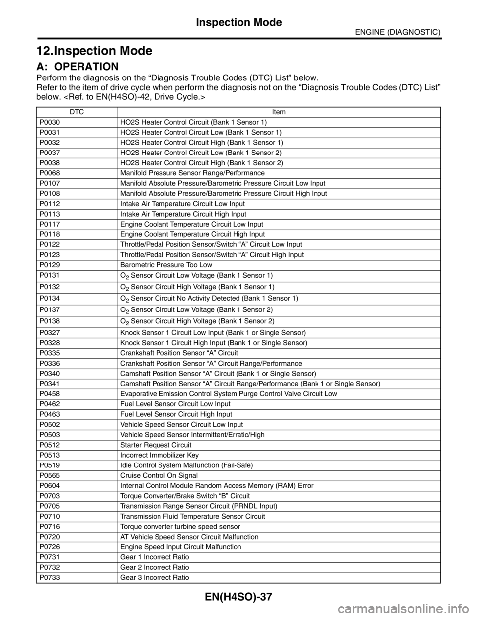
12.Inspection Mode
A: OPERATION
Perform the diagnosis on the “Diagnosis Trouble Codes (DTC) List” below.
Refer to the item of drive cycle when perform the diagnosis not on the “Diagnosis Trouble Codes (DTC) List”
below.
DTC Item
P0030 HO2S Heater Control Circuit (Bank 1 Sensor 1)
P0031 HO2S Heater Control Circuit Low (Bank 1 Sensor 1)
P0032 HO2S Heater Control Circuit High (Bank 1 Sensor 1)
P0037 HO2S Heater Control Circuit Low (Bank 1 Sensor 2)
P0038 HO2S Heater Control Circuit High (Bank 1 Sensor 2)
P0068 Manifold Pressure Sensor Range/Performance
P0107 Manifold Absolute Pressure/Barometric Pressure Circuit Low Input
P0108 Manifold Absolute Pressure/Barometric Pressure Circuit High Input
P0112 Intake Air Temperature Circuit Low Input
P0113 Intake Air Temperature Circuit High Input
P0117 Engine Coolant Temperature Circuit Low Input
P0118 Engine Coolant Temperature Circuit High Input
P0122 Throttle/Pedal Position Sensor/Switch “A” Circuit Low Input
P0123 Throttle/Pedal Position Sensor/Switch “A” Circuit High Input
P0129 Barometric Pressure Too Low
P0131 O
2 Sensor Circuit Low Voltage (Bank 1 Sensor 1)
P0132 O
2 Sensor Circuit High Voltage (Bank 1 Sensor 1)
P0134 O
2 Sensor Circuit No Activity Detected (Bank 1 Sensor 1)
P0137 O
2 Sensor Circuit Low Voltage (Bank 1 Sensor 2)
P0138 O
2 Sensor Circuit High Voltage (Bank 1 Sensor 2)
P0327 Knock Sensor 1 Circuit Low Input (Bank 1 or Single Sensor)
P0328 Knock Sensor 1 Circuit High Input (Bank 1 or Single Sensor)
P0335 Crankshaft Position Sensor “A” Circuit
P0336 Crankshaft Position Sensor “A” Circuit Range/Performance
P0340 Camshaft Position Sensor “A” Circuit (Bank 1 or Single Sensor)
P0341 Camshaft Position Sensor “A” Circuit Range/Performance (Bank 1 or Single Sensor)
P0458 Evaporative Emission Control System Purge Control Valve Circuit Low
P0462 Fuel Level Sensor Circuit Low Input
P0463 Fuel Level Sensor Circuit High Input
P0502 Vehicle Speed Sensor Circuit Low Input
P0503 Vehicle Speed Sensor Intermittent/Erratic/High
P0512 Starter Request Circuit
P0513 Incorrect Immobilizer Key
P0519 Idle Control System Malfunction (Fail-Safe)
P0565 Cruise Control On Signal
P0604 Internal Control Module Random Access Memory (RAM) Error
P0703 Torque Converter/Brake Switch “B” Circuit
P0705 Transmission Range Sensor Circuit (PRNDL Input)
P0710 Transmission Fluid Temperature Sensor Circuit
P0716 Torque converter turbine speed sensor
P0720 AT Vehicle Speed Sensor Circuit Malfunction
P0726 Engine Speed Input Circuit Malfunction
P0731 Gear 1 Incorrect Ratio
P0732 Gear 2 Incorrect Ratio
P0733 Gear 3 Incorrect Ratio
Page 1171 of 2870
EN(H4SO)-73
ENGINE (DIAGNOSTIC)
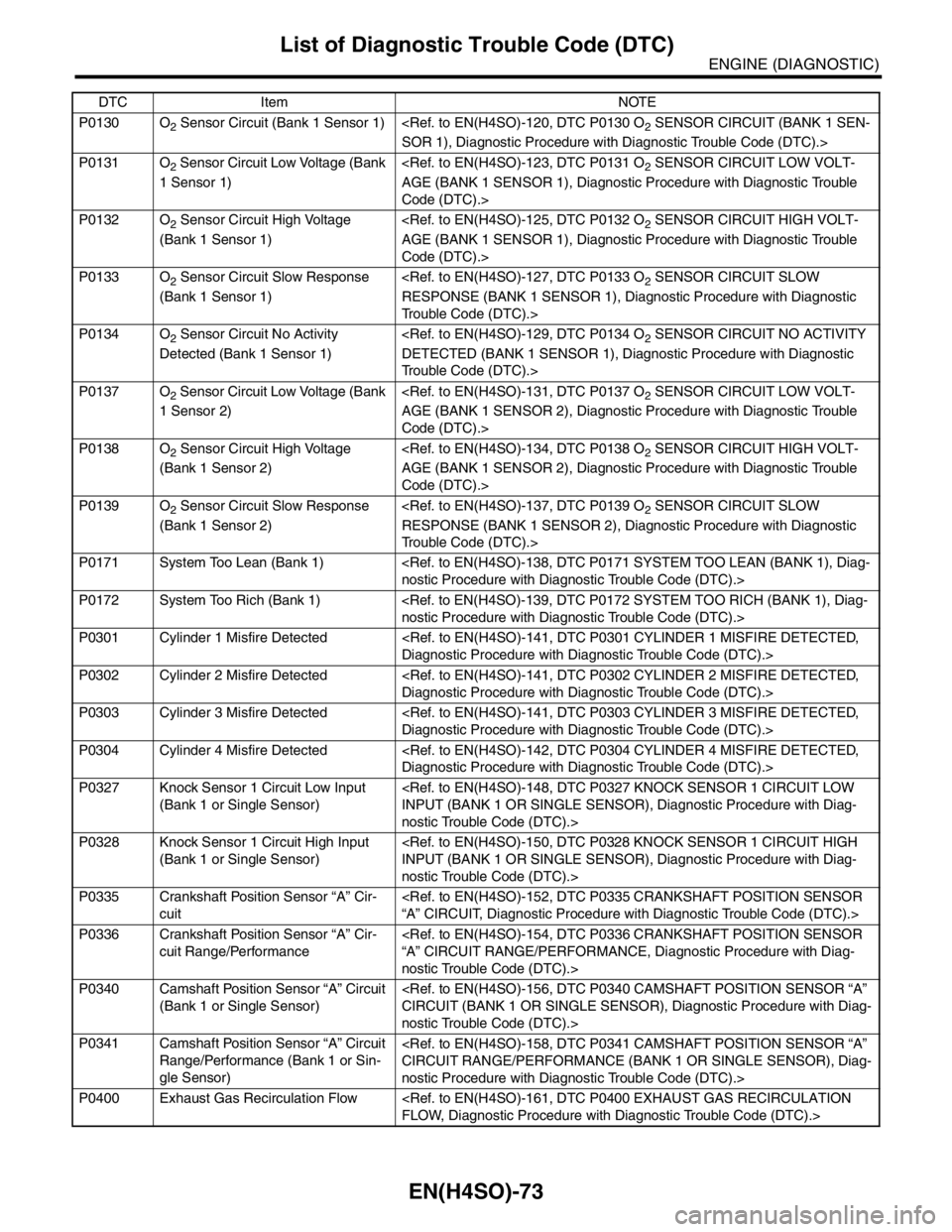
List of Diagnostic Trouble Code (DTC)
P0130 O2 Sensor Circuit (Bank 1 Sensor 1)
P0131 O
2 Sensor Circuit Low Voltage (Bank
1 Sensor 1)
Code (DTC).>
P0132 O
2 Sensor Circuit High Voltage
(Bank 1 Sensor 1)
Code (DTC).>
P0133 O
2 Sensor Circuit Slow Response
(Bank 1 Sensor 1)
Trouble Code (DTC).>
P0134 O
2 Sensor Circuit No Activity
Detected (Bank 1 Sensor 1)
Trouble Code (DTC).>
P0137 O
2 Sensor Circuit Low Voltage (Bank
1 Sensor 2)
Code (DTC).>
P0138 O
2 Sensor Circuit High Voltage
(Bank 1 Sensor 2)
Code (DTC).>
P0139 O
2 Sensor Circuit Slow Response
(Bank 1 Sensor 2)
Trouble Code (DTC).>
P0171 System Too Lean (Bank 1)
P0172 System Too Rich (Bank 1)
P0301 Cylinder 1 Misfire Detected
P0302 Cylinder 2 Misfire Detected
P0303 Cylinder 3 Misfire Detected
P0304 Cylinder 4 Misfire Detected
P0327 Knock Sensor 1 Circuit Low Input
(Bank 1 or Single Sensor)
nostic Trouble Code (DTC).>
P0328 Knock Sensor 1 Circuit High Input
(Bank 1 or Single Sensor)
nostic Trouble Code (DTC).>
P0335 Crankshaft Position Sensor “A” Cir-
cuit
P0336 Crankshaft Position Sensor “A” Cir-
cuit Range/Performance
nostic Trouble Code (DTC).>
P0340 Camshaft Position Sensor “A” Circuit
(Bank 1 or Single Sensor)
nostic Trouble Code (DTC).>
P0341 Camshaft Position Sensor “A” Circuit
Range/Performance (Bank 1 or Sin-
gle Sensor)
nostic Procedure with Diagnostic Trouble Code (DTC).>
P0400 Exhaust Gas Recirculation Flow
Page 1242 of 2870
EN(H4SO)-144
ENGINE (DIAGNOSTIC)
Diagnostic Procedure with Diagnostic Trouble Code (DTC)
6 CHECK POWER SUPPLY LINE.
1) Turn the ignition switch to ON.
2) Measure the voltage between fuel injector
and engine ground on faulty cylinders.
Connector & terminal
#1 (E5) No. 2 (+) — Engine ground (
−):
#2 (E16) No. 2 (+) — Engine ground (
−):
#3 (E6) No. 2 (+) — Engine ground (
−):
#4 (E17) No. 2 (+) — Engine ground (
−):Is the voltage more than 10 V? Repair poor con-
tact in all connec-
tors in fuel injector
circuit.Repair harness
and connector.
N
OTE:
In this case repair
the following:
Open circuit in
harness between
main relay and fuel
injector connector
on faulty cylinders
Poor contact in
coupling connector
Poor contact in
main relay connec-
tor
Poor contact in
fuel injector con-
nector on faulty
cylinders
7 CHECK HARNESS BETWEEN FUEL INJEC-
TOR AND ECM CONNECTOR.
1) Turn the ignition switch to OFF.
2) Disconnect the connector from fuel injector
on faulty cylinder.
3) Turn the ignition switch to ON.
4) Measure the voltage between ECM con-
nector and chassis ground on faulty cylinders.
Connector & terminal
#1 (B134) No. 34 (+) — Chassis ground (
−):
#2 (B134) No. 23 (+) — Chassis ground (
−):
#3 (B134) No. 22 (+) — Chassis ground (
−):
#4 (B134) No. 8 (+) — Chassis ground (
−):Is the voltage more than 10 V? Repair battery
short circuit in har-
ness between
ECM and fuel
injector. After
repair, replace the
ECM.
Engine Control
Module (ECM).>Go to step 8.
8 CHECK FUEL INJECTOR.
1) Turn the ignition switch to OFF.
2) Measure the resistance between fuel injec-
tor terminals on faulty cylinder.
Te r m i n a l s
No. 1 — No. 2:Is the resistance less than 1
Ω?Replace the faulty
fuel injector
Fuel Injector.> and
ECM.
Engine Control
Module (ECM).>Go to step 9.
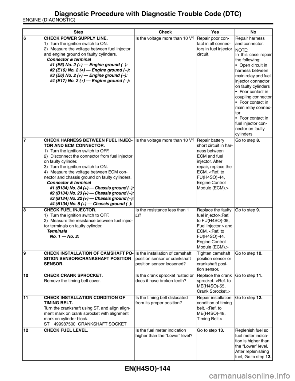
9 CHECK INSTALLATION OF CAMSHAFT PO-
SITION SENSOR/CRANKSHAFT POSITION
SENSOR.Is the installation of camshaft
position sensor or crankshaft
position sensor loosened?Tighten camshaft
position sensor or
crankshaft posi-
tion sensor.Go to step 10.
10 CHECK CRANK SPROCKET.
Remove the timing belt cover.Is the crank sprocket rusted or
does it have broken teeth?Replace the crank
sprocket.
Crank Sprocket.>Go to step 11.
11 CHECK INSTALLATION CONDITION OF
TIMING BELT.
Turn the crankshaft using ST, and align align-
ment mark on crank sprocket with alignment
mark on cylinder block.
ST 499987500 CRANKSHAFT SOCKETIs the timing belt dislocated
from its proper position?Repair installation
condition of timing
belt.
Timing Belt.>Go to step 12.
12 CHECK FUEL LEVEL.Is the fuel meter indication
higher than the “Lower” level?Go to step 13.Replenish fuel so
fuel meter indica-
tion is higher than
the “Lower” level.
After replenishing
fuel, Go to step 13. Step Check Yes No
Page 1254 of 2870

EN(H4SO)-156
ENGINE (DIAGNOSTIC)
Diagnostic Procedure with Diagnostic Trouble Code (DTC)
AK:DTC P0340 CAMSHAFT POSITION SENSOR “A” CIRCUIT (BANK 1 OR SIN-
GLE SENSOR)
DTC DETECTING CONDITION:
Immediately at fault recognition
TROUBLE SYMPTOM:
Engine stalls.
Failure of engine to start
CAUTION:
After repair or replacement of faulty parts, conduct Clear Memory Mode
WIRING DIAGRAM:
EN-00274
B22
E15
12
125678
131415169101112
34
17181920
12
2018
1828
B22
E3
E15
B135ECM CAMSHAFT
POSITION
SENSOR
7
B135
567
82 1
94
310
24 22 23 251112131415
26 27
281617181920 21
Page 1255 of 2870
EN(H4SO)-157
ENGINE (DIAGNOSTIC)
Diagnostic Procedure with Diagnostic Trouble Code (DTC)
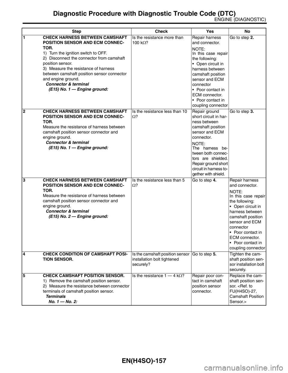
Step Check Yes No
1 CHECK HARNESS BETWEEN CAMSHAFT
POSITION SENSOR AND ECM CONNEC-
TOR.
1) Turn the ignition switch to OFF.
2) Disconnect the connector from camshaft
position sensor.
3) Measure the resistance of harness
between camshaft position sensor connector
and engine ground.
Connector & terminal
(E15) No. 1 — Engine ground:Is the resistance more than
100 kΩ?Repair harness
and connector.
N
OTE:
In this case repair
the following:
Open circuit in
harness between
camshaft position
sensor and ECM
connector
Poor contact in
ECM connector.
Poor contact in
coupling connectorGo to step 2.
2 CHECK HARNESS BETWEEN CAMSHAFT
POSITION SENSOR AND ECM CONNEC-
TOR.
Measure the resistance of harness between
camshaft position sensor connector and
engine ground.
Connector & terminal
(E15) No. 1 — Engine ground:Is the resistance less than 10
Ω?Repair ground
short circuit in har-
ness between
camshaft position
sensor and ECM
connector.
N
OTE:
The harness be-
tween both connec-
tors are shielded.
Repair ground short
circuit in harness to-
gether with shield.Go to step 3.
3 CHECK HARNESS BETWEEN CAMSHAFT
POSITION SENSOR AND ECM CONNEC-
TOR.
Measure the resistance of harness between
camshaft position sensor connector and
engine ground.
Connector & terminal
(E15) No. 2 — Engine ground:Is the resistance less than 5
Ω?Go to step 4.Repair harness
and connector.
NOTE:
In this case repair
the following:
Open circuit in
harness between
camshaft position
sensor and ECM
connector
Poor contact in
ECM connector.
Poor contact in
coupling connector
4 CHECK CONDITION OF CAMSHAFT POSI-
TION SENSOR.Is the camshaft position sensor
installation bolt tightened
securely?Go to step 5.Tighten the cam-
shaft position sen-
sor installation bolt
securely.
5 CHECK CAMSHAFT POSITION SENSOR.
1) Remove the camshaft position sensor.
2) Measure the resistance between connector
terminals of camshaft position sensor.
Te r m i n a l s
No. 1 — No. 2:Is the resistance 1 — 4 kΩ? Repair poor con-
tact in camshaft
position sensor
connector.Replace the cam-
shaft position sen-
sor.
Camshaft Position
Sensor.>
Page 1256 of 2870

EN(H4SO)-158
ENGINE (DIAGNOSTIC)
Diagnostic Procedure with Diagnostic Trouble Code (DTC)
AL:DTC P0341 CAMSHAFT POSITION SENSOR “A” CIRCUIT RANGE/PERFOR-
MANCE (BANK 1 OR SINGLE SENSOR)
DTC DETECTING CONDITION:
Immediately at fault recognition
TROUBLE SYMPTOM:
Engine stalls
Failure of engine to start
CAUTION:
After repair or replacement of faulty parts, conduct Clear Memory Mode
WIRING DIAGRAM:
EN-00274
B22
E15
12
125678
131415169101112
34
17181920
12
2018
1828
B22
E3
E15
B135ECM CAMSHAFT
POSITION
SENSOR
7
B135
567
82 1
94
310
24 22 23 251112131415
26 27
281617181920 21
Page 1257 of 2870
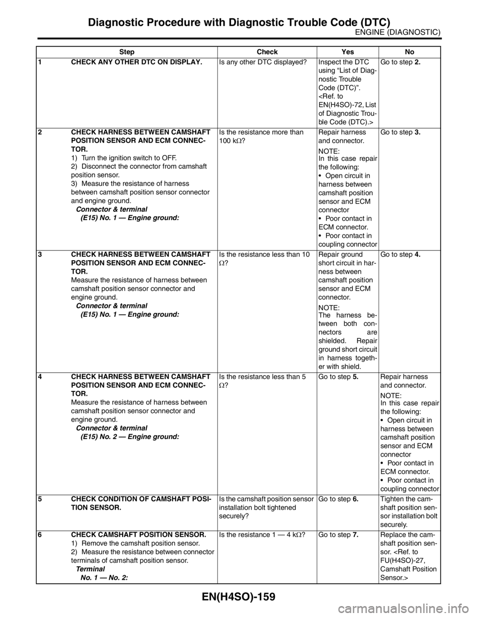
EN(H4SO)-159
ENGINE (DIAGNOSTIC)
Diagnostic Procedure with Diagnostic Trouble Code (DTC)
Step Check Yes No
1 CHECK ANY OTHER DTC ON DISPLAY.Is any other DTC displayed? Inspect the DTC
using “List of Diag-
nostic Trouble
Code (DTC)”.
of Diagnostic Trou-
ble Code (DTC).>Go to step 2.
2 CHECK HARNESS BETWEEN CAMSHAFT
POSITION SENSOR AND ECM CONNEC-
TOR.
1) Turn the ignition switch to OFF.
2) Disconnect the connector from camshaft
position sensor.
3) Measure the resistance of harness
between camshaft position sensor connector
and engine ground.
Connector & terminal
(E15) No. 1 — Engine ground:Is the resistance more than
100 kΩ?Repair harness
and connector.
N
OTE:
In this case repair
the following:
Open circuit in
harness between
camshaft position
sensor and ECM
connector
Poor contact in
ECM connector.
Poor contact in
coupling connectorGo to step 3.
3 CHECK HARNESS BETWEEN CAMSHAFT
POSITION SENSOR AND ECM CONNEC-
TOR.
Measure the resistance of harness between
camshaft position sensor connector and
engine ground.
Connector & terminal
(E15) No. 1 — Engine ground:Is the resistance less than 10
Ω?Repair ground
short circuit in har-
ness between
camshaft position
sensor and ECM
connector.
N
OTE:
The harness be-
tween both con-
nectors are
shielded. Repair
ground short circuit
in harness togeth-
er with shield.Go to step 4.
4 CHECK HARNESS BETWEEN CAMSHAFT
POSITION SENSOR AND ECM CONNEC-
TOR.
Measure the resistance of harness between
camshaft position sensor connector and
engine ground.
Connector & terminal
(E15) No. 2 — Engine ground:Is the resistance less than 5
Ω?Go to step 5.Repair harness
and connector.
N
OTE:
In this case repair
the following:
Open circuit in
harness between
camshaft position
sensor and ECM
connector
Poor contact in
ECM connector.
Poor contact in
coupling connector
5 CHECK CONDITION OF CAMSHAFT POSI-
TION SENSOR.Is the camshaft position sensor
installation bolt tightened
securely?Go to step 6.Tighten the cam-
shaft position sen-
sor installation bolt
securely.
6 CHECK CAMSHAFT POSITION SENSOR.
1) Remove the camshaft position sensor.
2) Measure the resistance between connector
terminals of camshaft position sensor.
Te r m i n a l
No. 1 — No. 2:Is the resistance 1 — 4 kΩ? Go to step 7.Replace the cam-
shaft position sen-
sor.
Camshaft Position
Sensor.>