Page 967 of 2870
ME(H4SO)-96
MECHANICAL
Engine Noise
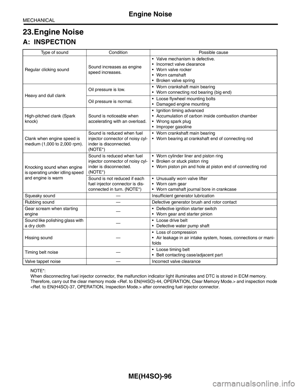
23.Engine Noise
A: INSPECTION
NOTE*:
When disconnecting fuel injector connector, the malfunction indicator light illuminates and DTC is stored in ECM memory.
Therefore, carry out the clear memory mode and inspection mode
after connecting fuel injector connector.Type of sound Condition Possible cause
Regular clicking soundSound increases as engine
speed increases. Valve mechanism is defective.
Incorrect valve clearance
Worn valve rocker
Worn camshaft
Broken valve spring
Heavy and dull clankOil pressure is low. Worn crankshaft main bearing
Worn connecting rod bearing (big end)
Oil pressure is normal. Loose flywheel mounting bolts
Damaged engine mounting
High-pitched clank (Spark
knock)Sound is noticeable when
accelerating with an overload. Ignition timing advanced
Accumulation of carbon inside combustion chamber
Wrong spark plug
Improper gasoline
Clank when engine speed is
medium (1,000 to 2,000 rpm).Sound is reduced when fuel
injector connector of noisy cyl-
inder is disconnected.
(NOTE*) Worn crankshaft main bearing
Worn bearing at crankshaft end of connecting rod
Knocking sound when engine
is operating under idling speed
and engine is warmSound is reduced when fuel
injector connector of noisy cyl-
inder is disconnected.
(NOTE*) Worn cylinder liner and piston ring
Broken or stuck piston ring
Worn piston pin and hole at piston end of connecting rod
Sound is not reduced if each
fuel injector connector is dis-
connected in turn. (NOTE*) Unusually worn valve lifter
Worn cam gear
Worn camshaft journal bore in crankcase
Squeaky sound — Insufficient generator lubrication
Rubbing sound — Defective generator brush and rotor contact
Gear scream when starting
engine— Defective ignition starter switch
Worn gear and starter pinion
Sound like polishing glass with
a dry cloth— Loose drive belt
Defective water pump shaft
Hissing sound — Loss of compression
Air leakage in air intake system, hoses, connections or mani-
folds
Timing belt noise — Loose timing belt
Belt contacting case/adjacent part
Valve tappet noise — Incorrect valve clearance
Page 1004 of 2870
CO(H4SO)-21
COOLING
Water Pump
4. Water Pump
A: REMOVAL
1. NON-TURBO MODEL
1) Remove the radiator.
REMOVAL, Radiator.>
2) Remove the V-belts.
3) Remove the timing belt.
AL, Timing Belt.>
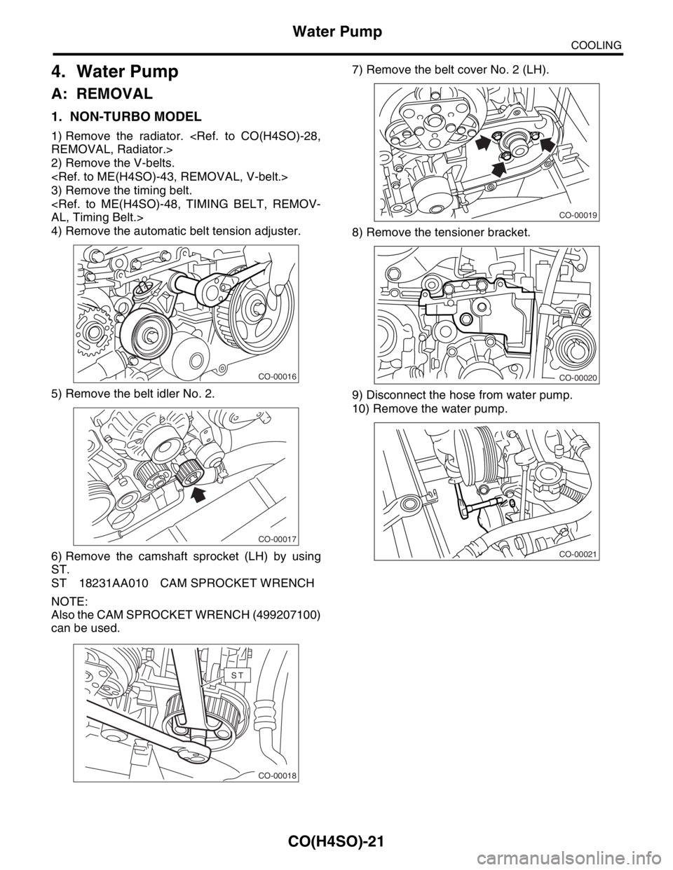
4) Remove the automatic belt tension adjuster.
5) Remove the belt idler No. 2.
6) Remove the camshaft sprocket (LH) by using
ST.
ST 18231AA010 CAM SPROCKET WRENCH
NOTE:
Also the CAM SPROCKET WRENCH (499207100)
can be used.7) Remove the belt cover No. 2 (LH).
8) Remove the tensioner bracket.
9) Disconnect the hose from water pump.
10) Remove the water pump.
CO-00016
CO-00017
CO-00018
ST
CO-00019
CO-00020
CO-00021
Page 1005 of 2870
CO(H4SO)-22
COOLING
Water Pump
2. TURBO MODEL
1) Remove the radiator.
REMOVAL, Radiator.>
2) Remove the V-belts.
REMOVAL, V-belt.>
3) Remove the timing belt.
58, REMOVAL, Timing Belt Assembly.>
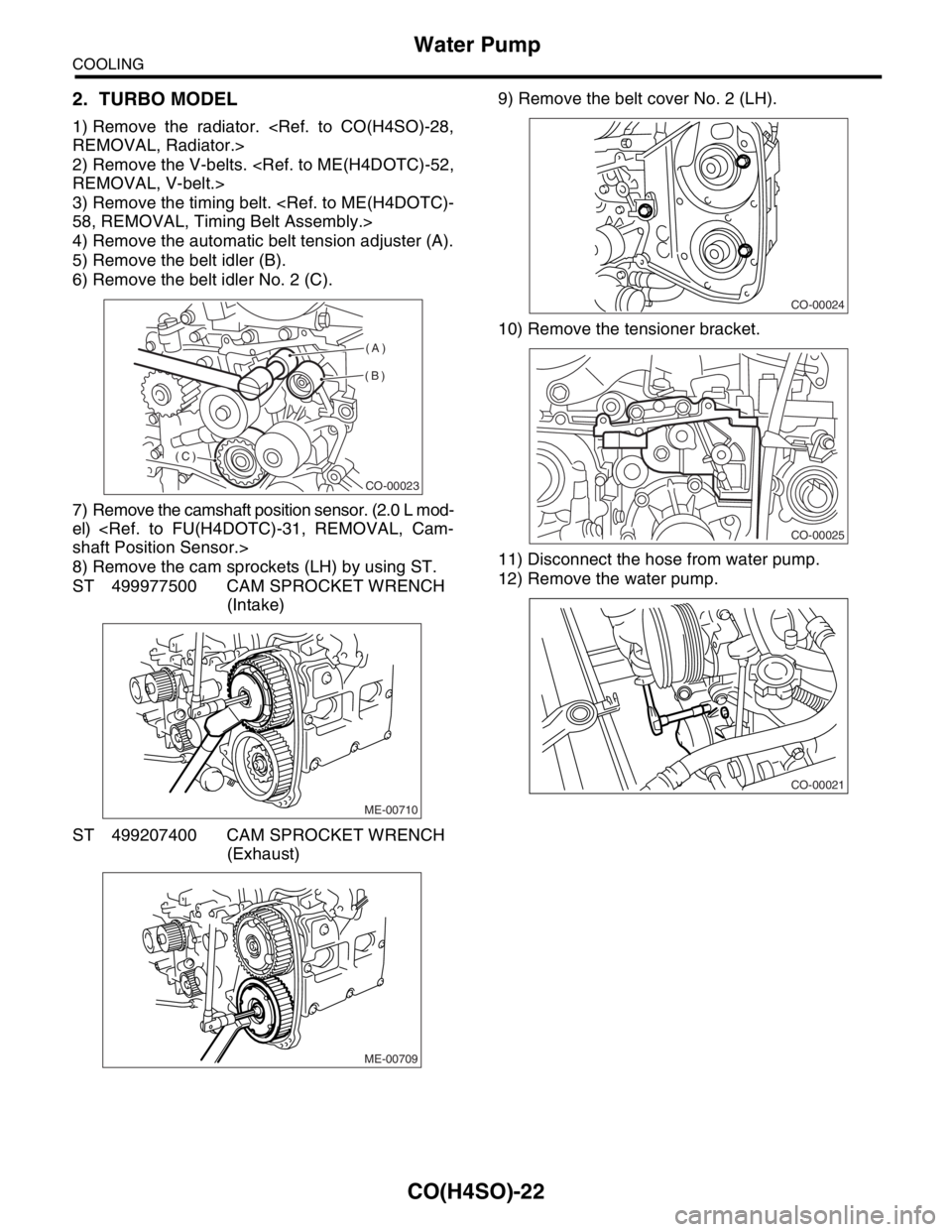
4) Remove the automatic belt tension adjuster (A).
5) Remove the belt idler (B).
6) Remove the belt idler No. 2 (C).
7) Remove the camshaft position sensor. (2.0 L mod-
el)
shaft Position Sensor.>
8) Remove the cam sprockets (LH) by using ST.
ST 499977500 CAM SPROCKET WRENCH
(Intake)
ST 499207400 CAM SPROCKET WRENCH
(Exhaust)9) Remove the belt cover No. 2 (LH).
10) Remove the tensioner bracket.
11) Disconnect the hose from water pump.
12) Remove the water pump.
CO-00023
(A)
(B)
(C)
ME-00710
ME-00709
CO-00024
CO-00025
CO-00021
Page 1006 of 2870
CO(H4SO)-23
COOLING
Water Pump
B: INSTALLATION
1. NON-TURBO MODEL
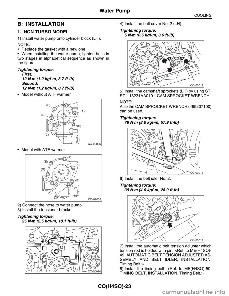
1) Install water pump onto cylinder block (LH).
NOTE:
Replace the gasket with a new one.
When installing the water pump, tighten bolts in
two stages in alphabetical sequence as shown in
the figure.
Tightening torque:
First:
12 N
⋅m (1.2 kgf-m, 8.7 ft-lb)
Second:
12 N
⋅m (1.2 kgf-m, 8.7 ft-lb)
Model without ATF warmer
Model with ATF warmer
2) Connect the hose to water pump.
3) Install the tensioner bracket.
Tightening torque:
25 N
⋅m (2.5 kgf-m, 18.1 ft-lb)4) Install the belt cover No. 2 (LH).
Tightening torque:
5 N
⋅m (0.5 kgf-m, 3.6 ft-lb)
5) Install the camshaft sprockets (LH) by using ST.
ST 18231AA010 CAM SPROCKET WRENCH
NOTE:
Also the CAM SPROCKET WRENCH (499207100)
can be used.
Tightening torque:
78 N
⋅m (8.0 kgf-m, 57.9 ft-lb)
6) Install the belt idler No. 2.
Tightening torque:
39 N
⋅m (4.0 kgf-m, 28.9 ft-lb)
7) Install the automatic belt tension adjuster which
tension rod is holded with pin.
49, AUTOMATIC BELT TENSION ADJUSTER AS-
SEMBLY AND BELT IDLER, INSTALLATION,
Timing Belt.>
8) Install the timing belt.
TIMING BELT, INSTALLATION, Timing Belt.>
CO-00026
(E)
(D)
(B)
(C)(A) (F)
CO-02008
(B) (C) (D)(E)(F)
(A)
CO-00020
CO-00019
CO-00018
ST
CO-00017
Page 1007 of 2870
CO(H4SO)-24
COOLING
Water Pump
9) Install the V-belts.
STALLATION, V-belt.>
10) Install the radiator.
STALLATION, Radiator.>
2. TURBO MODEL
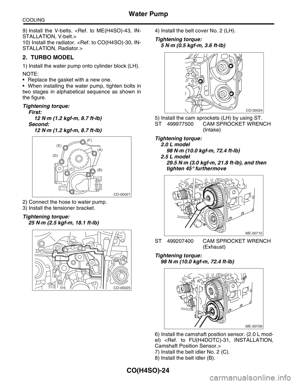
1) Install the water pump onto cylinder block (LH).
NOTE:
Replace the gasket with a new one.
When installing the water pump, tighten bolts in
two stages in alphabetical sequence as shown in
the figure.
Tightening torque:
First:
12 N
⋅m (1.2 kgf-m, 8.7 ft-lb)
Second:
12 N
⋅m (1.2 kgf-m, 8.7 ft-lb)
2) Connect the hose to water pump.
3) Install the tensioner bracket.
Tightening torque:
25 N
⋅m (2.5 kgf-m, 18.1 ft-lb)4) Install the belt cover No. 2 (LH).
Tightening torque:
5 N
⋅m (0.5 kgf-m, 3.6 ft-lb)
5) Install the cam sprockets (LH) by using ST.
ST 499977500 CAM SPROCKET WRENCH
(Intake)
Tightening torque:
2.0 L model
98 N
⋅m (10.0 kgf-m, 72.4 ft-lb)
2.5 L model
29.5 N
⋅m (3.0 kgf-m, 21.8 ft-lb), and then
tighten 45
° furthermove
ST 499207400 CAM SPROCKET WRENCH
(Exhaust)
Tightening torque:
98 N
⋅m (10.0 kgf-m, 72.4 ft-lb)
6) Install the camshaft position sensor. (2.0 L mod-
el)
Camshaft Position Sensor.>
7) Install the belt idler No. 2 (C).
8) Install the belt idler (B).
CO-00027
(B) (C) (D)(E)(F)
(A)
CO-00025
CO-00024
ME-00710
ME-00709
Page 1109 of 2870
EN(H4SO)-11
ENGINE (DIAGNOSTIC)
Electrical Component Location
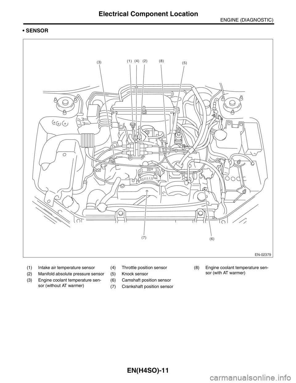
SENSOR
EN-02379
(1)(2)
(3)(4)
(5)
(6) (7)(8)
(1) Intake air temperature sensor (4) Throttle position sensor (8) Engine coolant temperature sen-
sor (with AT warmer)
(2) Manifold absolute pressure sensor (5) Knock sensor
(3) Engine coolant temperature sen-
sor (without AT warmer)(6) Camshaft position sensor
(7) Crankshaft position sensor
Page 1119 of 2870
EN(H4SO)-21
ENGINE (DIAGNOSTIC)
Engine Control Module (ECM) I/O Signal
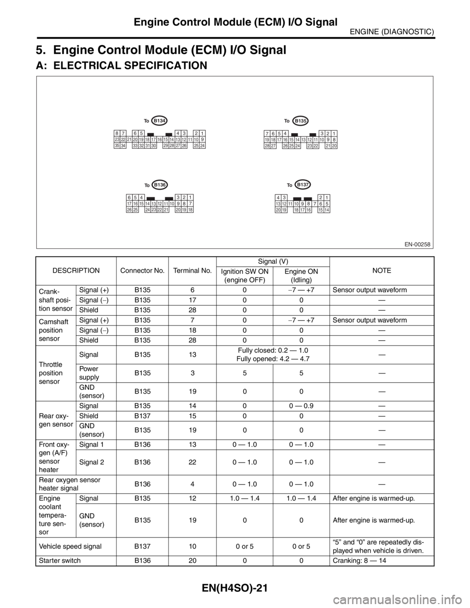
5. Engine Control Module (ECM) I/O Signal
A: ELECTRICAL SPECIFICATION
DESCRIPTION Connector No. Terminal No.Signal (V)
NOTE
Ignition SW ON
(engine OFF)Engine ON
(Idling)
Crank-
shaft posi-
tion sensorSignal (+) B135 6 0−7 — +7 Sensor output waveform
Signal (−) B135 17 0 0 —
Shield B135 28 0 0 —
Camshaft
position
sensorSignal (+) B135 7 0−7 — +7 Sensor output waveform
Signal (−) B135 18 0 0 —
Shield B135 28 0 0 —
Throttle
position
sensorSignal B135 13Fully closed: 0.2 — 1.0
Fully opened: 4.2 — 4.7—
Pow er
supplyB135 3 5 5 —
GND
(sensor)B135 19 0 0 —
Rear oxy-
gen sensorSignal B135 14 0 0 — 0.9 —
Shield B137 15 0 0 —
GND
(sensor)B135 19 0 0 —
Fr o nt ox y-
gen (A/F)
sensor
heaterSignal 1 B136 13 0 — 1.0 0 — 1.0 —
Signal 2 B136 22 0 — 1.0 0 — 1.0 —
Rear oxygen sensor
heater signalB136 4 0 — 1.0 0 — 1.0 —
Engine
coolant
tempera-
ture sen-
sorSignal B135 12 1.0 — 1.4 1.0 — 1.4 After engine is warmed-up.
GND
(sensor)B135 19 0 0 After engine is warmed-up.
Vehicle speed signal B137 10 0 or 5 0 or 5“5” and “0” are repeatedly dis-
played when vehicle is driven.
Starter switch B136 20 0 0 Cranking: 8 — 14
EN-00258
B135B134
B137B136
1234567891011121314151617181920
1 2 3 4
5
6
7 8
910 11 12 13 14 15
16
17 18
19 20 21
22 23
24
25 26 27
28
29
30 31 32
33
34 351 2 3
4
5
6
7
8 910 11
12
13 14
15 16 17
18 19
20
21 22
23 24 25
26 27
28
1 2
3
4 5 6
7
8
910
11 12
13 14 15 16
17
18 19 20 21 22 23
24
25 26
To
To
To To
Page 1129 of 2870
EN(H4SO)-31
ENGINE (DIAGNOSTIC)
Subaru Select Monitor
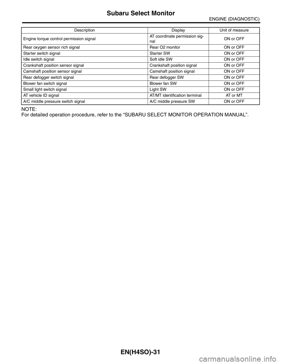
NOTE:
For detailed operation procedure, refer to the “SUBARU SELECT MONITOR OPERATION MANUAL”.
Engine torque control permission signalAT coordinate permission sig-
nalON or OFF
Rear oxygen sensor rich signal Rear O2 monitor ON or OFF
Starter switch signal Starter SW ON or OFF
Idle switch signal Soft idle SW ON or OFF
Crankshaft position sensor signal Crankshaft position signal ON or OFF
Camshaft position sensor signal Camshaft position signal ON or OFF
Rear defogger switch signal Rear defogger SW ON or OFF
Blower fan switch signal Blower fan SW ON or OFF
Small light switch signal Light SW ON or OFF
AT vehicle ID signal AT/MT identification terminal AT or MT
A/C middle pressure switch signal A/C middle pressure SW ON or OFFDescription Display Unit of measure