2004 SUBARU FORESTER Camshaft
[x] Cancel search: CamshaftPage 924 of 2870
ME(H4SO)-53
MECHANICAL
Cam Sprocket
16.Cam Sprocket
A: REMOVAL
1. REMOVAL
1) Remove the V-belt.
2) Remove the crank pulley.
3) Remove the belt cover.
4) Remove the timing belt assembly.
5) Remove the camshaft position sensor.
Sensor.>
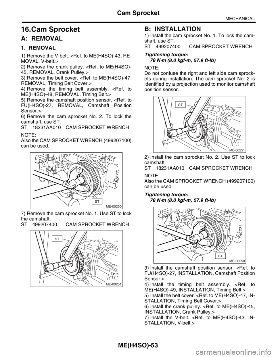
6) Remove the cam sprocket No. 2. To lock the
camshaft, use ST.
ST 18231AA010 CAM SPROCKET WRENCH
NOTE:
Also the CAM SPROCKET WRENCH (499207100)
can be used.
7) Remove the cam sprocket No. 1. Use ST to lock
the camshaft.
ST 499207400 CAM SPROCKET WRENCH
B: INSTALLATION
1) Install the cam sprocket No. 1. To lock the cam-
shaft, use ST.
ST 499207400 CAM SPROCKET WRENCH
Tightening torque:
78 N
⋅m (8.0 kgf-m, 57.9 ft-lb)
NOTE:
Do not confuse the right and left side cam sprock-
ets during installation. The cam sprocket No. 2 is
identified by a projection used to monitor camshaft
position sensor.
2) Install the cam sprocket No. 2. Use ST to lock
camshaft.
ST 18231AA010 CAM SPROCKET WRENCH
NOTE:
Also the CAM SPROCKET WRENCH (499207100)
can be used.
Tightening torque:
78 N
⋅m (8.0 kgf-m, 57.9 ft-lb)
3) Install the camshaft position sensor.
Sensor.>
4) Install the timing belt assembly.
5) Install the belt cover.
6) Install the crank pulley.
7) Install the V-belt.
ME-00250
ST
ME-00251
ST
ME-00251
ST
ME-00250
ST
Page 929 of 2870
ME(H4SO)-58
MECHANICAL
Camshaft
19.Camshaft
A: REMOVAL
1) Remove the V-belt.
2) Remove the crank pulley.
3) Remove the belt cover.
4) Remove the timing belt assembly.
5) Remove the cam sprocket.
6) Remove the crank sprocket.
7) Remove the belt cover No. 2 (LH).
8) Remove the belt cover No. 2 (RH).
NOTE:
Do not damage or lose the seal rubber when re-
moving belt covers.
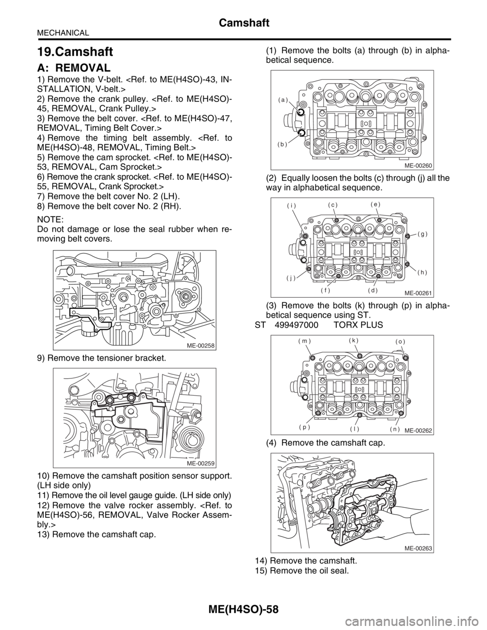
9) Remove the tensioner bracket.
10) Remove the camshaft position sensor support.
(LH side only)
11) Remove the oil level gauge guide. (LH side only)
12) Remove the valve rocker assembly.
bly.>
13) Remove the camshaft cap.(1) Remove the bolts (a) through (b) in alpha-
betical sequence.
(2) Equally loosen the bolts (c) through (j) all the
way in alphabetical sequence.
(3) Remove the bolts (k) through (p) in alpha-
betical sequence using ST.
ST 499497000 TORX PLUS
(4) Remove the camshaft cap.
14) Remove the camshaft.
15) Remove the oil seal.
ME-00258
ME-00259
ME-00260
(b)(a)
ME-00261
(c)(e)
(g)
(h)
(d) (f) (j)(i)
ME-00262
(k)
(o)
(n) (l) (p) (m)
ME-00263
Page 930 of 2870
ME(H4SO)-59
MECHANICAL
Camshaft
16) Remove the plug from rear side of camshaft.
CAUTION:
Do not remove the oil seal unless necessary.
Do not scratch the journal surface when re-
moving oil seal.
B: INSTALLATION
1) Apply a coat of engine oil to the camshaft jour-
nals, and then install the camshaft.
2) Install the camshaft cap.
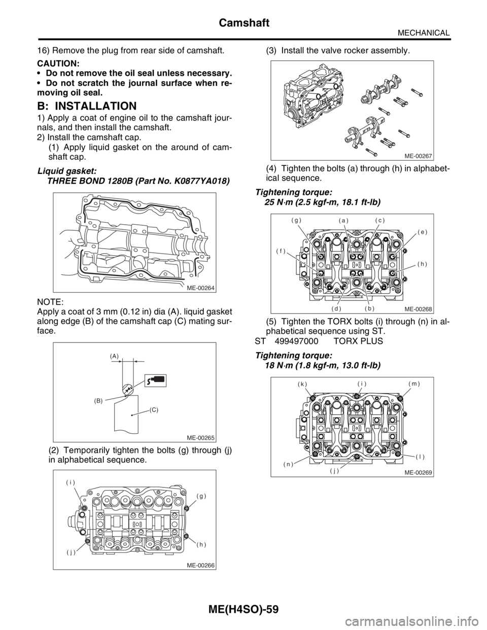
(1) Apply liquid gasket on the around of cam-
shaft cap.
Liquid gasket:
THREE BOND 1280B (Part No. K0877YA018)
NOTE:
Apply a coat of 3 mm (0.12 in) dia (A). liquid gasket
along edge (B) of the camshaft cap (C) mating sur-
face.
(2) Temporarily tighten the bolts (g) through (j)
in alphabetical sequence.(3) Install the valve rocker assembly.
(4) Tighten the bolts (a) through (h) in alphabet-
ical sequence.
Tightening torque:
25 N
⋅m (2.5 kgf-m, 18.1 ft-lb)
(5) Tighten the TORX bolts (i) through (n) in al-
phabetical sequence using ST.
ST 499497000 TORX PLUS
Tightening torque:
18 N
⋅m (1.8 kgf-m, 13.0 ft-lb)
ME-00264
ME-00265
(A)
(B)
(C)
ME-00266
(g)
(h)
(j) (i)
ME-00267
ME-00268
(a)
(b)(c)
(d)(e)
(f)(g)
(h)
ME-00269
(i)
(j)(m)
(n)(k)
(l)
Page 931 of 2870
ME(H4SO)-60
MECHANICAL
Camshaft
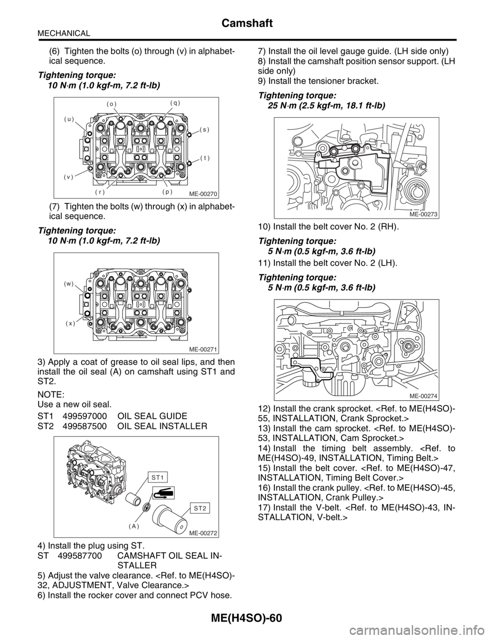
(6) Tighten the bolts (o) through (v) in alphabet-
ical sequence.
Tightening torque:
10 N
⋅m (1.0 kgf-m, 7.2 ft-lb)
(7) Tighten the bolts (w) through (x) in alphabet-
ical sequence.
Tightening torque:
10 N
⋅m (1.0 kgf-m, 7.2 ft-lb)
3) Apply a coat of grease to oil seal lips, and then
install the oil seal (A) on camshaft using ST1 and
ST2.
NOTE:
Use a new oil seal.
ST1 499597000 OIL SEAL GUIDE
ST2 499587500 OIL SEAL INSTALLER
4) Install the plug using ST.
ST 499587700 CAMSHAFT OIL SEAL IN-
STALLER
5) Adjust the valve clearance.
6) Install the rocker cover and connect PCV hose.7) Install the oil level gauge guide. (LH side only)
8) Install the camshaft position sensor support. (LH
side only)
9) Install the tensioner bracket.
Tightening torque:
25 N
⋅m (2.5 kgf-m, 18.1 ft-lb)
10) Install the belt cover No. 2 (RH).
Tightening torque:
5 N
⋅m (0.5 kgf-m, 3.6 ft-lb)
11) Install the belt cover No. 2 (LH).
Tightening torque:
5 N
⋅m (0.5 kgf-m, 3.6 ft-lb)
12) Install the crank sprocket.
13) Install the cam sprocket.
14) Install the timing belt assembly.
15) Install the belt cover.
16) Install the crank pulley.
17) Install the V-belt.
ME-00270
(o)
(r)(q)
(v)(u)
(p)(s)
(t)
ME-00271
(x) (w)
ME-00272(A)
ST2
ST1
ME-00273
ME-00274
Page 932 of 2870
ME(H4SO)-61
MECHANICAL
Camshaft
C: INSPECTION
1. CAMSHAFT
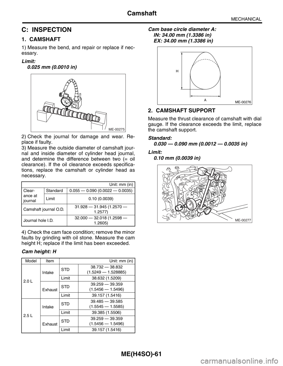
1) Measure the bend, and repair or replace if nec-
essary.
Limit:
0.025 mm (0.0010 in)
2) Check the journal for damage and wear. Re-
place if faulty.
3) Measure the outside diameter of camshaft jour-
nal and inside diameter of cylinder head journal,
and determine the difference between two (= oil
clearance). If the oil clearance exceeds specifica-
tions, replace the camshaft or cylinder head as
necessary.
4) Check the cam face condition; remove the minor
faults by grinding with oil stone. Measure the cam
height H; replace if the limit has been exceeded.
Cam height: HCam base circle diameter A:
IN: 34.00 mm (1.3386 in)
EX: 34.00 mm (1.3386 in)
2. CAMSHAFT SUPPORT
Measure the thrust clearance of camshaft with dial
gauge. If the clearance exceeds the limit, replace
the camshaft support.
Standard:
0.030 — 0.090 mm (0.0012 — 0.0035 in)
Limit:
0.10 mm (0.0039 in)
Unit: mm (in)
Clear-
ance at
journalStandard 0.055 — 0.090 (0.0022 — 0.0035)
Limit 0.10 (0.0039)
Camshaft journal O.D.31.928 — 31.945 (1.2570 —
1.2577)
Journal hole I.D.32.000 — 32.018 (1.2598 —
1.2605)
Model Item Unit: mm (in)
2.0 LIntakeSTD38.732 — 38.832
(1.5249 — 1.528885)
Limit 38.632 (1.5209)
ExhaustSTD39.259 — 39.359
(1.5456 — 1.5496)
Limit 39.157 (1.5416)
2.5 LIntakeSTD39.485 — 39.585
(1.5545 — 1.5585)
Limit 39.385 (1.5506)
ExhaustSTD39.259 — 39.359
(1.5456 — 1.5496)
Limit 39.157 (1.5416)
ME-00275
ME-00276
H
A
ME-00277
Page 933 of 2870
ME(H4SO)-62
MECHANICAL
Cylinder Head
20.Cylinder Head
A: REMOVAL
1) Remove the V-belt.
2) Remove the crank pulley.
3) Remove the timing belt cover.
4) Remove the timing belt.
5) Remove the cam sprocket.
6) Remove the intake manifold.
7) Remove the bolt which installs A/C compressor
bracket on cylinder head.
8) Remove the valve rocker assembly.
bly.>
9) Remove the camshaft.
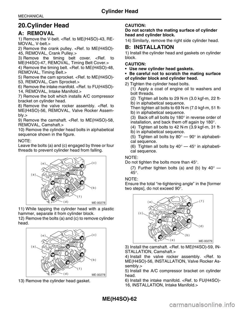
10) Remove the cylinder head bolts in alphabetical
sequence shown in the figure.
NOTE:
Leave the bolts (a) and (c) engaged by three or four
threads to prevent cylinder head from falling.
11) While tapping the cylinder head with a plastic
hammer, separate it from cylinder block.
12) Remove the bolts (a) and (c) to remove cylinder
head.
13) Remove the cylinder head gasket.CAUTION:
Do not scratch the mating surface of cylinder
head and cylinder block.
14) Similarly, remove the right side cylinder head.
B: INSTALLATION
1) Install the cylinder head and gaskets on cylinder
block.
CAUTION:
Use new cylinder head gaskets.
Be careful not to scratch the mating surface
of cylinder block and cylinder head.
2) Tighten the cylinder head bolts.
(1) Apply a coat of engine oil to washers and
bolt threads.
(2) Tighten all bolts to 29 N⋅m (3.0 kgf-m, 22 ft-
lb) in alphabetical sequence.
Then tighten all bolts to 69 N⋅m (7.0 kgf-m, 51 ft-
lb) in alphabetical sequence.
(3) Back off all bolts by 180° in reverse order of
installation, and back them off again by 180°.
(4) Tighten all bolts to 42 N⋅m (3.9 kgf-m, 31 ft-
lb) in alphabetical sequence.
(5) Tighten all bolts by 80° — 90° in alphabeti-
cal sequence.
(6) Tighten all bolts by 40° — 45° in alphabeti-
cal sequence.
NOTE:
Do not tighten the bolts more than 45°.
(7) Further tighten bolts (a) and (b) by 40° —
45°.
NOTE:
Ensure the total “re-tightening angle” in the [former
two steps], do not exceed 90°.
3) Install the camshaft.
4) Install the valve rocker assembly.
sembly.>
5) Install the A/C compressor bracket on cylinder
head.
6) Install the intake manifold.
ME-00278
(c)
(b)
(f)
(d) (a)(e)
ME-00278
(c)
(b)
(f)
(d) (a)(e)
ME-00279
(c)
(b)(f)
(d) (a)
(e)
Page 935 of 2870
ME(H4SO)-64
MECHANICAL
Cylinder Head
D: ASSEMBLY
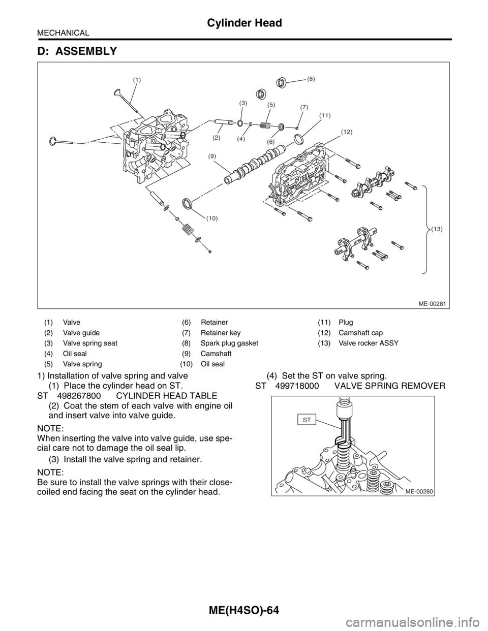
1) Installation of valve spring and valve
(1) Place the cylinder head on ST.
ST 498267800 CYLINDER HEAD TABLE
(2) Coat the stem of each valve with engine oil
and insert valve into valve guide.
NOTE:
When inserting the valve into valve guide, use spe-
cial care not to damage the oil seal lip.
(3) Install the valve spring and retainer.
NOTE:
Be sure to install the valve springs with their close-
coiled end facing the seat on the cylinder head.(4) Set the ST on valve spring.
ST 499718000 VALVE SPRING REMOVER
(1) Valve (6) Retainer (11) Plug
(2) Valve guide (7) Retainer key (12) Camshaft cap
(3) Valve spring seat (8) Spark plug gasket (13) Valve rocker ASSY
(4) Oil seal (9) Camshaft
(5) Valve spring (10) Oil seal
ME-00281 (10)(9)(6) (1)
(2)(3)
(4)(5)
(7)(8)
(11)
(13) (12)
ME-00280
ST
Page 962 of 2870
ME(H4SO)-91
MECHANICAL
Engine Trouble in General
22.Engine Trouble in General
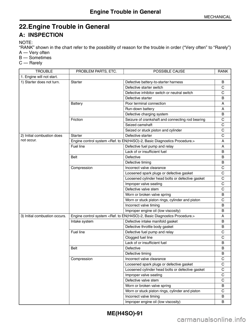
A: INSPECTION
NOTE:
“RANK” shown in the chart refer to the possibility of reason for the trouble in order (“Very often” to “Rarely”)
A — Very often
B — Sometimes
C — Rarely
TROUBLE PROBLEM PARTS, ETC. POSSIBLE CAUSE RANK
1. Engine will not start.
1) Starter does not turn. Starter Defective battery-to-starter harness B
Defective starter switch C
Defective inhibitor switch or neutral switch C
Defective starter B
Battery Poor terminal connection A
Run-down battery A
Defective charging system B
Friction Seizure of crankshaft and connecting rod bearing C
Seized camshaft C
Seized or stuck piston and cylinder C
2) Initial combustion does
not occur. Starter Defective starter C
Engine control system
Fuel line Defective fuel pump and relay A
Lack of or insufficient fuel B
Belt Defective B
Defective timing B
Compression Incorrect valve clearance C
Loosened spark plugs or defective gasket C
Loosened cylinder head bolts or defective gasket C
Improper valve seating C
Defective valve stem C
Worn or broken valve spring B
Worn or stuck piston rings, cylinder and piston C
Incorrect valve timing B
Improper engine oil (low viscosity) B
3) Initial combustion occurs. Engine control system
Intake system Defective intake manifold gasket B
Defective throttle body gasket B
Fuel line Defective fuel pump and relay C
Clogged fuel line C
Lack of or insufficient fuel B
Belt Defective B
Defective timing B
Compression Incorrect valve clearance C
Loosened spark plugs or defective gasket C
Loosened cylinder head bolts or defective gasket C
Improper valve seating C
Defective valve stem C
Worn or broken valve spring B
Worn or stuck piston rings, cylinder and piston C
Incorrect valve timing B
Improper engine oil (low viscosity) B