2004 SUBARU FORESTER tow
[x] Cancel search: towPage 2774 of 2870
5MT-61
MANUAL TRANSMISSION AND DIFFERENTIAL
Reverse Check Sleeve
E: INSPECTION
Make sure the cutout section of reverse accent
shaft is aligned with the opening in reverse check
sleeve.
Spin the cam by hand for smooth rotation.
Move the cam and shaft all the way toward plate
and release.
If the cam does not return properly, replace the re-
verse check spring; if shaft does not, check for
scratches on the inner surface of sleeve. If sleeve
is in good order, replace the spring.
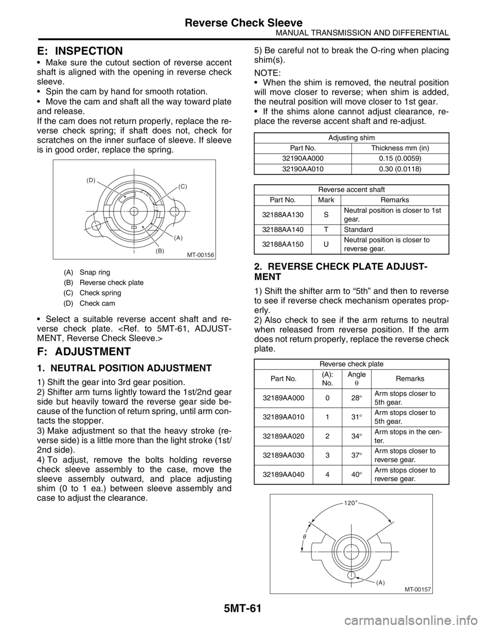
Select a suitable reverse accent shaft and re-
verse check plate.
F: ADJUSTMENT
1. NEUTRAL POSITION ADJUSTMENT
1) Shift the gear into 3rd gear position.
2) Shifter arm turns lightly toward the 1st/2nd gear
side but heavily toward the reverse gear side be-
cause of the function of return spring, until arm con-
tacts the stopper.
3) Make adjustment so that the heavy stroke (re-
verse side) is a little more than the light stroke (1st/
2nd side).
4) To adjust, remove the bolts holding reverse
check sleeve assembly to the case, move the
sleeve assembly outward, and place adjusting
shim (0 to 1 ea.) between sleeve assembly and
case to adjust the clearance.5) Be careful not to break the O-ring when placing
shim(s).
NOTE:
When the shim is removed, the neutral position
will move closer to reverse; when shim is added,
the neutral position will move closer to 1st gear.
If the shims alone cannot adjust clearance, re-
place the reverse accent shaft and re-adjust.
2. REVERSE CHECK PLATE ADJUST-
MENT
1) Shift the shifter arm to “5th” and then to reverse
to see if reverse check mechanism operates prop-
erly.
2) Also check to see if the arm returns to neutral
when released from reverse position. If the arm
does not return properly, replace the reverse check
plate.
(A) Snap ring
(B) Reverse check plate
(C) Check spring
(D) Check cam
MT-00156
(A) (D)
(B)(C)
Adjusting shim
Part No. Thickness mm (in)
32190AA000 0.15 (0.0059)
32190AA010 0.30 (0.0118)
Reverse accent shaft
Part No. Mark Remarks
32188AA130 SNeutral position is closer to 1st
gear.
32188AA140 T Standard
32188AA150 UNeutral position is closer to
reverse gear.
Reverse check plate
Par t No.(A):
No.Angle
θRemarks
32189AA000 0 28°Arm stops closer to
5th gear.
32189AA010 1 31°Arm stops closer to
5th gear.
32189AA020 2 34°Arm stops in the cen-
ter.
32189AA030 3 37°Arm stops closer to
reverse gear.
32189AA040 4 40°Arm stops closer to
reverse gear.
MT-00157(A)
Page 2794 of 2870
5MT-81
MANUAL TRANSMISSION AND DIFFERENTIAL
Main Shaft Assembly For Dual-Range
11) Install rest of the parts to the rear section of
transmission main shaft.
NOTE:
Align the convex part in baulk ring with shifting in-
sert.
12) Tighten the lock nuts to the specified torque us-
ing ST1 and ST2.
NOTE:
Secure the lock nuts in two places after tightening.
ST1 499987003 SOCKET WRENCH
ST2 498937000 TRANSMISSION HOLDER
Tightening torque:
120 N·m (12.2 kgf-m, 88.5 ft-lb)
13) Install the needle bearing on main shaft.14) Install the rest of parts to the front section of
transmission main shaft.
NOTE:
Be careful not to damage the graded section of
transmission main shaft when installing the needle
bearing.
Face the grooved side toward input gear.
Align the high-low baulk ring’s groove with shift-
ing insert.
15) Install a new snap ring to the rod section of
transmission main shaft using ST1 and ST2.
NOTE:
Select a suitable outer snap ring so that axial clear-
ance between snap ring and hub is held within
0.060 to 0.100 mm (0.0024 to 0.0039 in).
ST1 499757002 INSTALLER
ST2 499757001 SNAP RING GUIDE
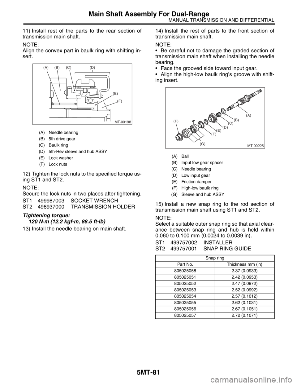
(A) Needle bearing
(B) 5th drive gear
(C) Baulk ring
(D) 5th-Rev sleeve and hub ASSY
(E) Lock washer
(F) Lock nuts
MT-00198
(A) (B) (C) (D)
(E)
(F)
(A) Ball
(B) Input low gear spacer
(C) Needle bearing
(D) Low input gear
(E) Friction damper
(F) High-low baulk ring
(G) Sleeve and hub ASSY
Snap ring
Part No. Thickness mm (in)
805025058 2.37 (0.0933)
805025051 2.42 (0.0953)
805025052 2.47 (0.0972)
805025053 2.52 (0.0992)
805025054 2.57 (0.1012)
805025055 2.62 (0.1031)
805025056 2.67 (0.1051)
805025057 2.72 (0.1071)
MT-00225
(F)
(G)(C)(B)(A)
(D)
(E)
(F)
Page 2810 of 2870

5MT-97
MANUAL TRANSMISSION AND DIFFERENTIAL
Front Differential Assembly
C: DISASSEMBLY
1. DIFFERENTIAL CASE ASSEMBLY
1) Loosen the twelve bolts and remove the hypoid
driven gear.
2) Drive out the straight pin from differential assem-
bly toward hypoid driven gear.
ST 899904100 REMOVER3) Pull out the pinion shaft, and remove the differ-
ential bevel pinion and gear and washer.
4) Remove the roller bearing using ST.
ST 899524100 PULLER SET
(A) Hypoid driven gear
(A)
MT-00275
MT-00276
ST
(A) Pinion shaft
(B) Differential bevel pinion
(C) Differential bevel gear
(D) Washer
MT-00277
(A)
(D)
(D)
(C)
(C)
(B)
(B)
MT-00278
ST
Page 2811 of 2870

5MT-98
MANUAL TRANSMISSION AND DIFFERENTIAL
Front Differential Assembly
2. SIDE RETAINER
NOTE:
Replace the oil seal and O-ring after adjustment of
drive pinion gear backlash and tooth contact.
1) Remove the O-ring.
2) Remove the oil seal.
NOTE:
Remove the oil seal using a flat tip screwdriver
Do not reuse the oil seal. Prepare a new oil seal.
D: ASSEMBLY
1. DIFFERENTIAL CASE ASSEMBLY
1) Install the differential bevel gear and bevel pin-
ion together with washers, and insert pinion shaft.
NOTE:
Face the chamfered side of washer toward gear.2) Measure the backlash between differential bevel
gear and pinion. If it is not within specifications, in-
stall a suitable washer to adjust it.
NOTE:
Be sure the pinion gear tooth contacts adjacent
gear teeth during measurement.
ST1 498247001 MAGNET BASE
ST2 498247100 DIAL GAUGE
Standard backlash:
0.13 — 0.18 mm (0.0051 — 0.0071 in)
3) Align the pinion shaft and differential case at
their holes, and drive the straight pin into holes
from the hypoid driven gear side, using ST.
NOTE:
Lock the straight pin after installing.
ST 899904100 REMOVER
(A) Differential bevel pinion
(B) Differential bevel gear
(C) Pinion shaft
MT-00279
MT-01003
MT-00284
(A) (B)
(C)
(A) Pinion shaft
(B) Differential case
(C) Straight pin
MT-00285
ST1
ST2
MT-00286
(A)
(C)
(B)
Page 2814 of 2870

5MT-101
MANUAL TRANSMISSION AND DIFFERENTIAL
Front Differential Assembly
3. TOOTH CONTACT OF HYPOID GEAR
Check the tooth contact of hypoid gear as follows:
Apply a uniform thin coat of red lead on both tooth
surfaces of 3 or 4 teeth of the hypoid gear. Move
the hypoid gear back and forth by turning the trans-
mission main shaft until a definite contact pattern is
developed on hypoid gear, and judge whether face
contact is correct. If it is inaccurate, make adjust-
ment.
Tooth contact is correct.
F: ADJUSTMENT
1. BEVEL PINION GEAR BACKLASH
1) Disassemble the front differential.
2) Select a different washer from the table and in-
stall.
3) Adjust until the specified value is obtained.
Standard backlash:
0.13 — 0.18 mm (0.0051 — 0.0071 in)
2. HYPOID GEAR BACKLASH
Adjust backlash by turning the holder in right side
case.
ST 499787000 WRENCH ASSY
NOTE:
Each time holder rotates one tooth, backlash
changes by 0.05 mm (0.0020 in).
3. TOOTH CONTACT OF HYPOID GEAR
1) Adjust until the teeth contact is correct.
2) Check and adjust the teeth contact with following
table.
Tooth contact
Checking item:Tooth contact pattern is slightly
shifted toward to toe side under no-load
rotation. [When loaded, contact pattern moves
toward heel.]
(A) Toe
(B) Coast side
(C) Heel
(D) Drive side
Washer
Part No. Thickness mm (in)
8030380210.925 — 0.950
(0.0364 — 0.0374)
8030380220.975 — 1.000
(0.0384 — 0.0394)
803038023 1.025 — 1.050
(0.0404 — 0.0413)
MT-00294
(A)
(B) (C)
(D)
(A) Toe side
(B) Heel side
MT-00176
ST
MT-00296
0.05mm(0.0020 in)
AT-00207
(A)
(B)
Page 2818 of 2870
5MT-105
MANUAL TRANSMISSION AND DIFFERENTIAL
Reverse Idler Gear
C: INSPECTION
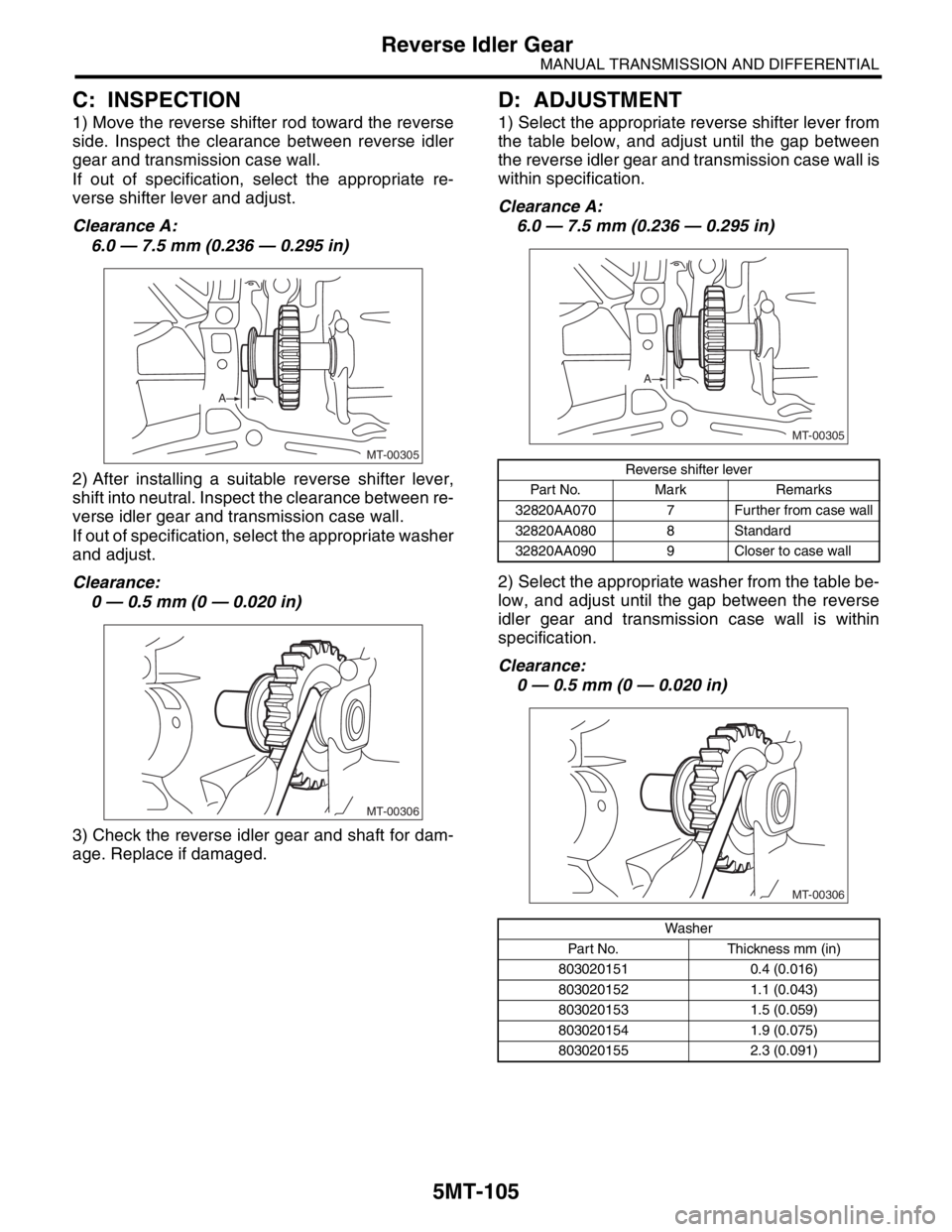
1) Move the reverse shifter rod toward the reverse
side. Inspect the clearance between reverse idler
gear and transmission case wall.
If out of specification, select the appropriate re-
verse shifter lever and adjust.
Clearance A:
6.0 — 7.5 mm (0.236 — 0.295 in)
2) After installing a suitable reverse shifter lever,
shift into neutral. Inspect the clearance between re-
verse idler gear and transmission case wall.
If out of specification, select the appropriate washer
and adjust.
Clearance:
0 — 0.5 mm (0 — 0.020 in)
3) Check the reverse idler gear and shaft for dam-
age. Replace if damaged.
D: ADJUSTMENT
1) Select the appropriate reverse shifter lever from
the table below, and adjust until the gap between
the reverse idler gear and transmission case wall is
within specification.
Clearance A:
6.0 — 7.5 mm (0.236 — 0.295 in)
2) Select the appropriate washer from the table be-
low, and adjust until the gap between the reverse
idler gear and transmission case wall is within
specification.
Clearance:
0 — 0.5 mm (0 — 0.020 in)
MT-00305
A
MT-00306
Reverse shifter lever
Part No. Mark Remarks
32820AA070 7 Further from case wall
32820AA080 8 Standard
32820AA090 9 Closer to case wall
Washer
Part No. Thickness mm (in)
803020151 0.4 (0.016)
803020152 1.1 (0.043)
803020153 1.5 (0.059)
803020154 1.9 (0.075)
803020155 2.3 (0.091)
MT-00305
A
MT-00306