Page 1527 of 2870
ME(H4DOTC)-69
MECHANICAL
Camshaft
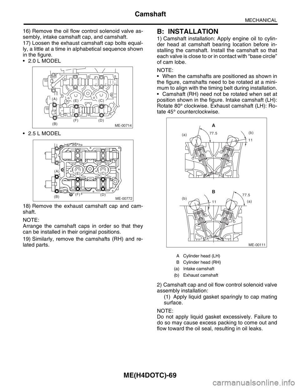
16) Remove the oil flow control solenoid valve as-
sembly, intake camshaft cap, and camshaft.
17) Loosen the exhaust camshaft cap bolts equal-
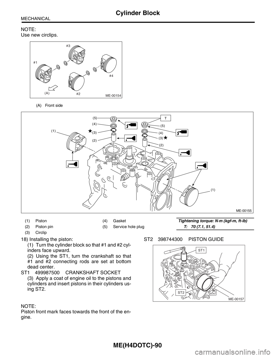
ly, a little at a time in alphabetical sequence shown
in the figure.
2.0 L MODEL
2.5 L MODEL
18) Remove the exhaust camshaft cap and cam-
shaft.
NOTE:
Arrange the camshaft caps in order so that they
can be installed in their original positions.
19) Similarly, remove the camshafts (RH) and re-
lated parts.B: INSTALLATION
1) Camshaft installation: Apply engine oil to cylin-
der head at camshaft bearing location before in-
stalling the camshaft. Install the camshaft so that
each valve is close to or in contact with “base circle”
of cam lobe.
NOTE:
When the camshafts are positioned as shown in
the figure, camshafts need to be rotated at a mini-
mum to align with the timing belt during installation.
Camshaft (RH) need not be rotated when set at
position shown in the figure. Intake camshaft (LH):
Rotate 80° clockwise. Exhaust camshaft (LH): Ro-
tate 45° counterclockwise.
2) Camshaft cap and oil flow control solenoid valve
assembly installation:
(1) Apply liquid gasket sparingly to cap mating
surface.
NOTE:
Do not apply liquid gasket excessively. Failure to
do so may cause excess packing to come out and
flow toward the oil seal, resulting in oil leaks.
ME-00714(B)
(A)
(E)
(F) (D)(C)
ME-00772
(A)(E)
(F)(B)(D)
(C)
A Cylinder head (LH)
B Cylinder head (RH)
(a) Intake camshaft
(b) Exhaust camshaft
ME-00111
1111
77.5 77.5
(a)
(b)
(a)(b)
A
B
Page 1550 of 2870
ME(H4DOTC)-90
MECHANICAL
Cylinder Block
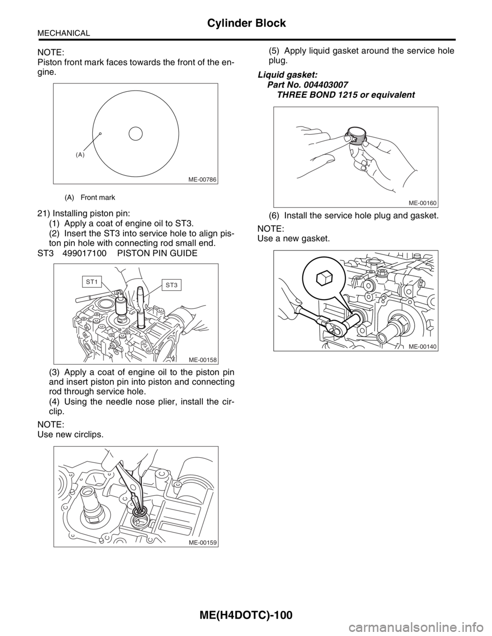
NOTE:
Use new circlips.
18) Installing the piston:
(1) Turn the cylinder block so that #1 and #2 cyl-
inders face upward.
(2) Using the ST1, turn the crankshaft so that
#1 and #2 connecting rods are set at bottom
dead center.
ST1 499987500 CRANKSHAFT SOCKET
(3) Apply a coat of engine oil to the pistons and
cylinders and insert pistons in their cylinders us-
ing ST2.ST2 398744300 PISTON GUIDE
NOTE:
Piston front mark faces towards the front of the en-
gine.
(A) Front side
ME-00154
#4 #3
#2 #1
(A)
(1) Piston (4) GasketTightening torque: N⋅m (kgf-m, ft-lb)
(2) Piston pin (5) Service hole plugT: 70 (7.1, 51.4)
(3) Circlip
ME-00155
(1) (1)
(2)
(2) (3)
(3) (4)
(4) (5)
(5)
T
ME-00157
ST2
ST1
Page 1560 of 2870
ME(H4DOTC)-100
MECHANICAL
Cylinder Block
NOTE:
Piston front mark faces towards the front of the en-
gine.
21) Installing piston pin:
(1) Apply a coat of engine oil to ST3.
(2) Insert the ST3 into service hole to align pis-
ton pin hole with connecting rod small end.
ST3 499017100 PISTON PIN GUIDE
(3) Apply a coat of engine oil to the piston pin
and insert piston pin into piston and connecting
rod through service hole.
(4) Using the needle nose plier, install the cir-
clip.
NOTE:
Use new circlips.(5) Apply liquid gasket around the service hole
plug.
Liquid gasket:
Part No. 004403007
THREE BOND 1215 or equivalent
(6) Install the service hole plug and gasket.
NOTE:
Use a new gasket.
(A) Front mark
ME-00786
(A)
ME-00158
ST1ST3
ME-00159
ME-00160
ME-00140
Page 1672 of 2870
EN(H4DOTC)-42
ENGINE (DIAGNOSTIC)
Inspection Mode
1. PREPARATION FOR THE INSPECTION
MODE
1) Check battery voltage is more than 12 V and fuel
remains half [20 to 402 (5.3 to 10.6 US gal, 4.4 to
8.8 Imp gal)].
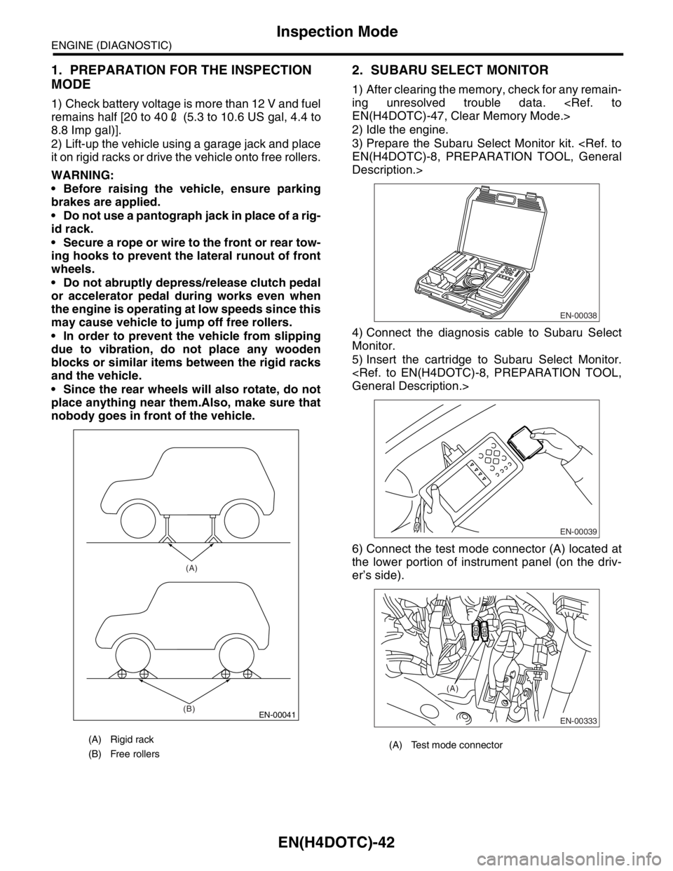
2) Lift-up the vehicle using a garage jack and place
it on rigid racks or drive the vehicle onto free rollers.
WARNING:
Before raising the vehicle, ensure parking
brakes are applied.
Do not use a pantograph jack in place of a rig-
id rack.
Secure a rope or wire to the front or rear tow-
ing hooks to prevent the lateral runout of front
wheels.
Do not abruptly depress/release clutch pedal
or accelerator pedal during works even when
the engine is operating at low speeds since this
may cause vehicle to jump off free rollers.
In order to prevent the vehicle from slipping
due to vibration, do not place any wooden
blocks or similar items between the rigid racks
and the vehicle.
Since the rear wheels will also rotate, do not
place anything near them.Also, make sure that
nobody goes in front of the vehicle.
2. SUBARU SELECT MONITOR
1) After clearing the memory, check for any remain-
ing unresolved trouble data.
EN(H4DOTC)-47, Clear Memory Mode.>
2) Idle the engine.
3) Prepare the Subaru Select Monitor kit.
EN(H4DOTC)-8, PREPARATION TOOL, General
Description.>
4) Connect the diagnosis cable to Subaru Select
Monitor.
5) Insert the cartridge to Subaru Select Monitor.
General Description.>
6) Connect the test mode connector (A) located at
the lower portion of instrument panel (on the driv-
er’s side).
(A) Rigid rack
(B) Free rollers
EN-00041
(A)
(B)
(A) Test mode connector
EN-00038
EN-00039
EN-00333
(A)
Page 1979 of 2870
FU(H4DOTC 2.5)-49
FUEL INJECTION (FUEL SYSTEM)
Fuel Filler Pipe
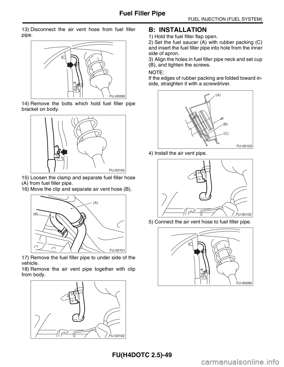
13) Disconnect the air vent hose from fuel filler
pipe.
14) Remove the bolts which hold fuel filler pipe
bracket on body.
15) Loosen the clamp and separate fuel filler hose
(A) from fuel filler pipe.
16) Move the clip and separate air vent hose (B).
17) Remove the fuel filler pipe to under side of the
vehicle.
18) Remove the air vent pipe together with clip
from body.B: INSTALLATION
1) Hold the fuel filler flap open.
2) Set the fuel saucer (A) with rubber packing (C)
and insert the fuel filler pipe into hole from the inner
side of apron.
3) Align the holes in fuel filler pipe neck and set cup
(B), and tighten the screws.
NOTE:
If the edges of rubber packing are folded toward in-
side, straighten it with a screwdriver.
4) Install the air vent pipe.
5) Connect the air vent hose to fuel filler pipe.
FU-00099
FU-00100
(A)
(B)
FU-00101
FU-00102
FU-00103
(A)
(C)
(B)
FU-00102
FU-00099
Page 2061 of 2870
EN(H4DOTC 2.5)-37
ENGINE (DIAGNOSTIC)
Inspection Mode
1. PREPARATION FOR THE INSPECTION
MODE
1) Check battery voltage is more than 12 V and fuel
remains half [20 — 402 (5.3 — 10.6 US gal, 4.4 —
8.8 Imp gal)].
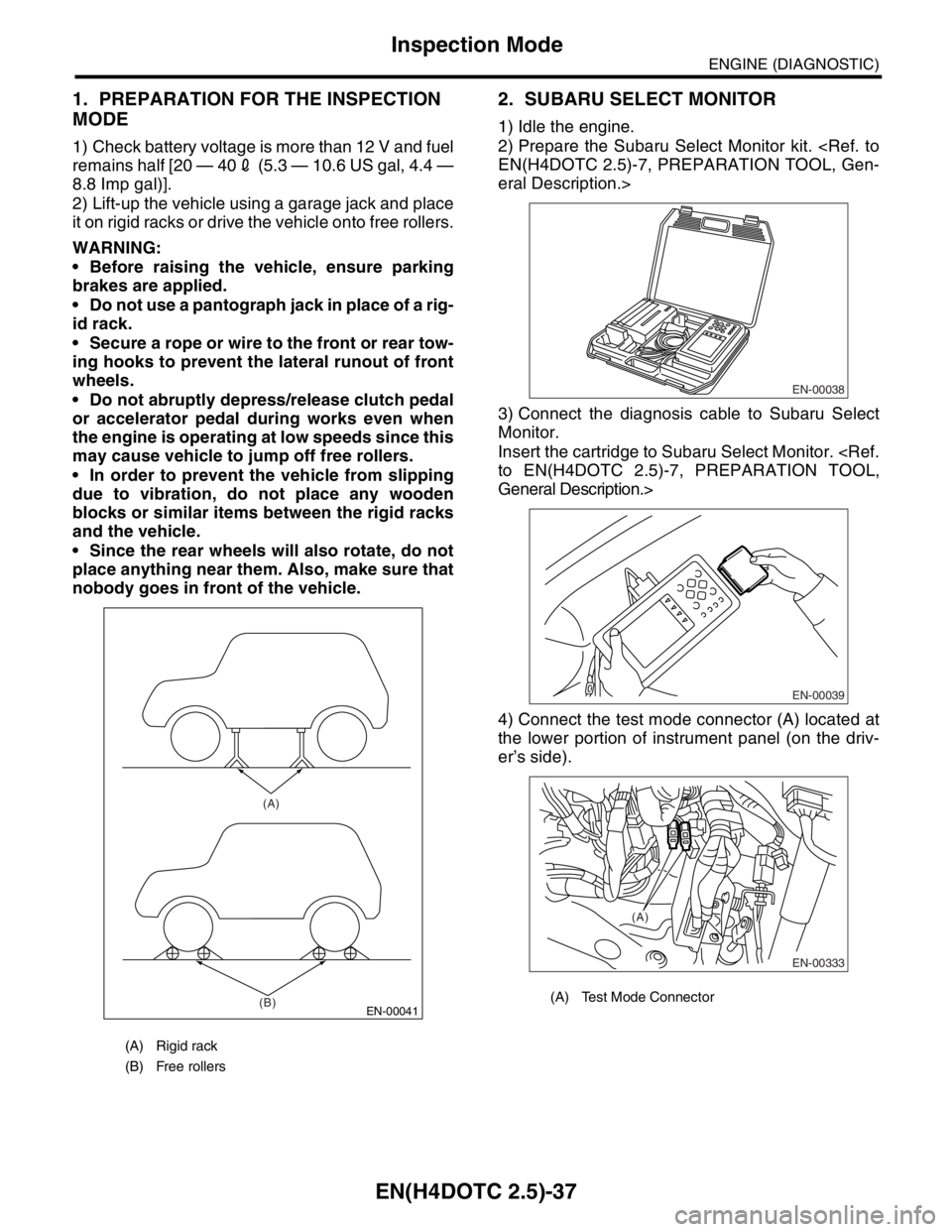
2) Lift-up the vehicle using a garage jack and place
it on rigid racks or drive the vehicle onto free rollers.
WARNING:
Before raising the vehicle, ensure parking
brakes are applied.
Do not use a pantograph jack in place of a rig-
id rack.
Secure a rope or wire to the front or rear tow-
ing hooks to prevent the lateral runout of front
wheels.
Do not abruptly depress/release clutch pedal
or accelerator pedal during works even when
the engine is operating at low speeds since this
may cause vehicle to jump off free rollers.
In order to prevent the vehicle from slipping
due to vibration, do not place any wooden
blocks or similar items between the rigid racks
and the vehicle.
Since the rear wheels will also rotate, do not
place anything near them. Also, make sure that
nobody goes in front of the vehicle.
2. SUBARU SELECT MONITOR
1) Idle the engine.
2) Prepare the Subaru Select Monitor kit.
EN(H4DOTC 2.5)-7, PREPARATION TOOL, Gen-
eral Description.>
3) Connect the diagnosis cable to Subaru Select
Monitor.
Insert the cartridge to Subaru Select Monitor.
to EN(H4DOTC 2.5)-7, PREPARATION TOOL,
General Description.>
4) Connect the test mode connector (A) located at
the lower portion of instrument panel (on the driv-
er’s side).
(A) Rigid rack
(B) Free rollers
EN-00041
(A)
(B)
(A) Test Mode Connector
EN-00038
EN-00039
EN-00333
(A)
Page 2428 of 2870
4AT-114
AUTOMATIC TRANSMISSION
Drive Pinion Shaft Assembly
10) Select three or less shims from following table.
E: INSPECTION
Make sure that all component parts are free of
harmful cut, gouges, and other faults.
Adjust the teeth alignment.
ADJUSTMENT, Drive Pinion Shaft Assembly.>
F: ADJUSTMENT
1) Remove the liquid gasket completely.
2) Install the oil pump housing assembly to torque
converter clutch case, and secure them with tight-
ening four bolts evenly.
NOTE:
Use an old gasket or an aluminum washer so as not
to damage the mating surface of housing.
Tightening torque:
41 N
⋅m (4.2 kgf-m, 30.4 ft-lb)
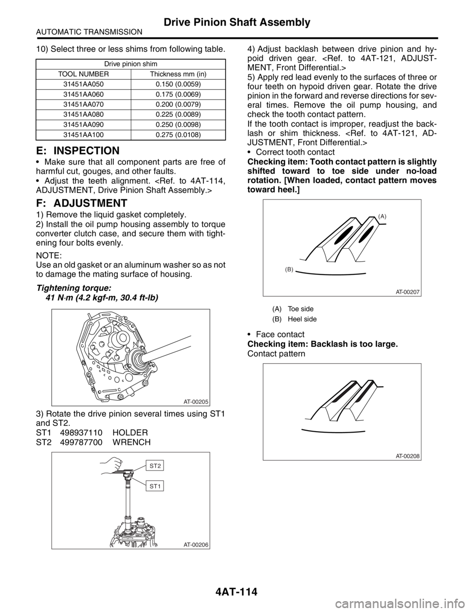
3) Rotate the drive pinion several times using ST1
and ST2.
ST1 498937110 HOLDER
ST2 499787700 WRENCH4) Adjust backlash between drive pinion and hy-
poid driven gear.
MENT, Front Differential.>
5) Apply red lead evenly to the surfaces of three or
four teeth on hypoid driven gear. Rotate the drive
pinion in the forward and reverse directions for sev-
eral times. Remove the oil pump housing, and
check the tooth contact pattern.
If the tooth contact is improper, readjust the back-
lash or shim thickness.
JUSTMENT, Front Differential.>
Correct tooth contact
Checking item: Tooth contact pattern is slightly
shifted toward to toe side under no-load
rotation. [When loaded, contact pattern moves
toward heel.]
Face contact
Checking item: Backlash is too large.
Contact pattern
Drive pinion shim
TOOL NUMBER Thickness mm (in)
31451AA050 0.150 (0.0059)
31451AA060 0.175 (0.0069)
31451AA070 0.200 (0.0079)
31451AA080 0.225 (0.0089)
31451AA090 0.250 (0.0098)
31451AA100 0.275 (0.0108)
AT-00205
AT-00206
ST2
ST1
(A) Toe side
(B) Heel side
AT-00207
(A)
(B)
AT-00208
Page 2747 of 2870
5MT-35
MANUAL TRANSMISSION AND DIFFERENTIAL
Manual Transmission Assembly
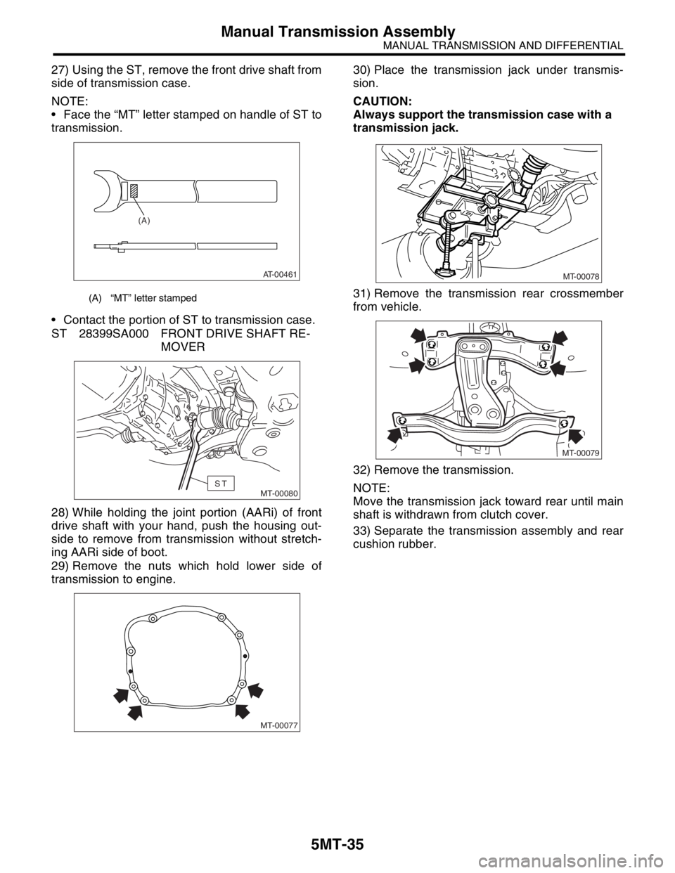
27) Using the ST, remove the front drive shaft from
side of transmission case.
NOTE:
Face the “MT” letter stamped on handle of ST to
transmission.
Contact the portion of ST to transmission case.
ST 28399SA000 FRONT DRIVE SHAFT RE-
MOVER
28) While holding the joint portion (AARi) of front
drive shaft with your hand, push the housing out-
side to remove from transmission without stretch-
ing AARi side of boot.
29) Remove the nuts which hold lower side of
transmission to engine.30) Place the transmission jack under transmis-
sion.
CAUTION:
Always support the transmission case with a
transmission jack.
31) Remove the transmission rear crossmember
from vehicle.
32) Remove the transmission.
NOTE:
Move the transmission jack toward rear until main
shaft is withdrawn from clutch cover.
33) Separate the transmission assembly and rear
cushion rubber.
(A) “MT” letter stamped
AT-00461
(A)
MT-00080ST
MT-00077
MT-00078
MT-00079