Page 2163 of 2870
EN(H4DOTC 2.5)-139
ENGINE (DIAGNOSTIC)
Diagnostic Procedure with Diagnostic Trouble Code (DTC)
AE:DTC P0345 CAMSHAFT POSITION SENSOR “A” CIRCUIT (BANK 2)
DTC DETECTING CONDITION:
Immediately at fault recognition
TROUBLE SYMPTOM:
Engine stalls.
Failure of engine to start
CAUTION:
After repair or replacement of faulty parts, conduct Clear Memory Mode
OPERATION, Clear Memory Mode.> and Inspection Mode
Inspection Mode.>.
WIRING DIAGRAM:
EN-02365
B47 1 2 3 5 4 6
E
E1
B20
B8
3 C35
SBF-5
E35
E1
B20
2E36
B21E2
1
107
3
B9
7
1
B122
2 1
ECM
B136B135 B:
C:
1
8
3412
56
123
4
56
78
9
1011 12
1314 15 16
B21
E36
B47
123
12 34
567
89
10
B20
B136
56
782 1
94 3
10
24 22 23 2511 12 13
1415
26 27
2816
17 18 19 20 21
33 34 29
32 30
31 35
B135
567
82 1
94 3
10
24 22 23 2511 12 13 14 15
26 27
2816 17 18 19
20 21
29 30 31 32 33 34 35
E35
B:C:
MAIN RELAY
BATTERY
CAMSHAFT
POSITION
SENSOR LHCAMSHAFT
POSITION
SENSOR RH
B122
12345678
Page 2164 of 2870

EN(H4DOTC 2.5)-140
ENGINE (DIAGNOSTIC)
Diagnostic Procedure with Diagnostic Trouble Code (DTC)
Step Check Yes No
1 CHECK POWER SUPPLY OF CAMSHAFT
POSITION SENSOR.
1) Turn the ignition switch to OFF.
2) Disconnect the connector from camshaft
position sensor.
3) Measure the voltage between camshaft
position sensor and engine ground.
Connector & terminal
(E35) No. 1 (+) — Engine ground (
−):Is the voltage more than 10 V? Repair the battery
short circuit
between main relay
connector and cam-
shaft position sen-
sor connector.Go to step 2.
2 CHECK POWER SUPPLY OF CAMSHAFT
POSITION SENSOR.
1) Turn the ignition switch to ON.
2) Measure the voltage between camshaft
position sensor and engine ground.
Connector & terminal
(E35) No. 1 (+) — Engine ground (
−):Is the voltage more than 10 V? Go to step 3.Repair open or
battery short cir-
cuit between main
relay connector
and camshaft
position sensor
connector.
3 CHECK HARNESS BETWEEN CAMSHAFT
POSITION SENSOR AND ECM.
1) Turn the ignition switch to OFF.
2) Disconnect the connector from ECM.
3) Measure the resistance between camshaft
position sensor and ECM.
Connector & terminal
(E35) No. 2 — (B135) No. 8:
(E35) No. 3 — (B136) No. 35:Is the resistance less than 1 Ω? Go to step 4.Repair open circuit
between camshaft
position sensor
and ECM.
4 CHECK HARNESS BETWEEN CAMSHAFT
POSITION SENSOR AND ECM.
Measure the resistance between camshaft
position sensor and engine ground.
Connector & terminal
(E35) No. 2 — Engine ground:
(E35) No. 3 — Engine ground:Is the resistance more than 1
MΩ?Go to step 5.Repair ground short
circuit between
camshaft position
sensor and ECM.
5 CHECK CONDITION OF CAMSHAFT POSI-
TION SENSOR.Is the camshaft position sensor
installation bolt tightened
securely?Go to step 6.Tighten the cam-
shaft position sen-
sor installation bolt
securely.
6 CHECK CAMSHAFT POSITION SENSOR.
Check waveform of camshaft position sensor.
Module (ECM) I/O Signal.>Is there any abnormality in
waveform?Replace the cam-
shaft position sen-
sor.
FU(H4DOTC 2.5)-
28, Camshaft
Position Sensor.>Go to step 7.
7 CHECK POOR CONTACT.
Check poor contact in ECM connector.Is there poor contact in ECM
connector?Repair the poor
contact in ECM
connector.Replace the ECM.
FU(H4DOTC 2.5)-
41, Engine Con-
trol Module
(ECM).>
Page 2165 of 2870
EN(H4DOTC 2.5)-141
ENGINE (DIAGNOSTIC)
Diagnostic Procedure with Diagnostic Trouble Code (DTC)
AF:DTC P0458 EVAPORATIVE EMISSION CONTROL SYSTEM PURGE CON-
TROL VALVE CIRCUIT LOW
DTC DETECTING CONDITION:
Two consecutive driving cycles with fault
TROUBLE SYMPTOM:
Erroneous idling
CAUTION:
After repair or replacement of faulty parts, conduct Clear Memory Mode
OPERATION, Clear Memory Mode.> and Inspection Mode
Inspection Mode.>.
WIRING DIAGRAM:
EN-02366
B47 1 2 3 5 4 6
E
B21
E2B47
B134
B134
E4 ECM
14 2 1
SBF-534 12
56
2 1
123
4
56
78
9
1011 12
1314 15 16
E4 B21
12
56 7
82 1
94 310
24 22 23 25 11 12 13 14 15
26 27
2816 17
18 19 20 21
33 34 29
32 30 31
MAIN RELAY
BATTERY
PURGE CONTROL
SOLENOID VALVE
Page 2166 of 2870

EN(H4DOTC 2.5)-142
ENGINE (DIAGNOSTIC)
Diagnostic Procedure with Diagnostic Trouble Code (DTC)
Step Check Yes No
1 CHECK OUTPUT SIGNAL FROM ECM.
1) Turn the ignition switch to ON.
2) Measure the voltage between ECM and
chassis ground.
Connector & terminal
(B134) No. 14 (+) — Chassis ground (
−):Is the voltage more than 10 V? Even if the mal-
function indicator
light illuminates,
the circuit has
returned to a nor-
mal condition at
this time.Go to step 2.
2 CHECK HARNESS BETWEEN PURGE CON-
TROL SOLENOID VALVE AND ECM CON-
NECTOR.
1) Turn the ignition switch to OFF.
2) Disconnect the connectors from purge con-
trol solenoid valve and ECM.
3) Measure the resistance of harness
between purge control solenoid valve connec-
tor and engine ground.
Connector & terminal
(E4) No. 2 — Engine ground:Is the resistance more than 1
MΩ?Go to step 3.Repair ground
short circuit in har-
ness between
ECM and purge
control solenoid
valve connector.
3 CHECK HARNESS BETWEEN PURGE CON-
TROL SOLENOID VALVE AND ECM CON-
NECTOR.
Measure the resistance of harness between
ECM and purge control solenoid valve of har-
ness connector.
Connector & terminal
(B134) No. 14 — (E4) No. 2:Is the resistance less than 1
Ω?Go to step 4.Repair open circuit
in harness between
ECM and purge
control solenoid
valve connector.
N
OTE:
In this case repair
the following:
Open circuit in
harness between
ECM and purge
control solenoid
valve connector
Poor contact in
coupling connector
4 CHECK PURGE CONTROL SOLENOID
VALVE.
1) Remove the purge control solenoid valve.
2) Measure the resistance between purge
control solenoid valve terminals.
Te r m i n a l s
No. 1 — No. 2:Is the resistance 10 — 100 Ω? Go to step 5.Replace the purge
control solenoid
valve.
EC(H4DOTC)-7,
Purge Control
Solenoid Valve.>
5 CHECK POWER SUPPLY TO PURGE CON-
TROL SOLENOID VALVE.
1) Turn the ignition switch to ON.
2) Measure the voltage between purge control
solenoid valve and engine ground.
Connector & terminal
(E4) No. 1 (+) — Engine ground (
−):Is the voltage more than 10 V? Go to step 6.Repair open circuit
in harness
between main
relay and purge
control solenoid
valve connector.
6 CHECK POOR CONTACT.
Check poor contact in purge control solenoid
valve connector.Is there poor contact in purge
control solenoid valve connec-
tor?Repair poor con-
tact in purge con-
trol solenoid valve
connector.Contact the SUB-
ARU dealer.
N
OTE:
Inspection by DTM
is required, be-
cause probable
cause is deteriora-
tion of multiple
parts.
Page 2167 of 2870
EN(H4DOTC 2.5)-143
ENGINE (DIAGNOSTIC)
Diagnostic Procedure with Diagnostic Trouble Code (DTC)
AG:DTC P0459 EVAPORATIVE EMISSION CONTROL SYSTEM PURGE CON-
TROL VALVE CIRCUIT HIGH
DTC DETECTING CONDITION:
Two consecutive driving cycles with fault
TROUBLE SYMPTOM:
Erroneous idling
CAUTION:
After repair or replacement of faulty parts, conduct Clear Memory Mode
OPERATION, Clear Memory Mode.> and Inspection Mode
Inspection Mode.>.
WIRING DIAGRAM:
EN-02366
B47 1 2 3 5 4 6
E
B21
E2B47
B134
B134
E4 ECM
14 2 1
SBF-534 12
56
2 1
123
4
56
78
9
1011 12
1314 15 16
E4 B21
12
56 7
82 1
94 310
24 22 23 25 11 12 13 14 15
26 27
2816 17
18 19 20 21
33 34 29
32 30 31
MAIN RELAY
BATTERY
PURGE CONTROL
SOLENOID VALVE
Page 2175 of 2870

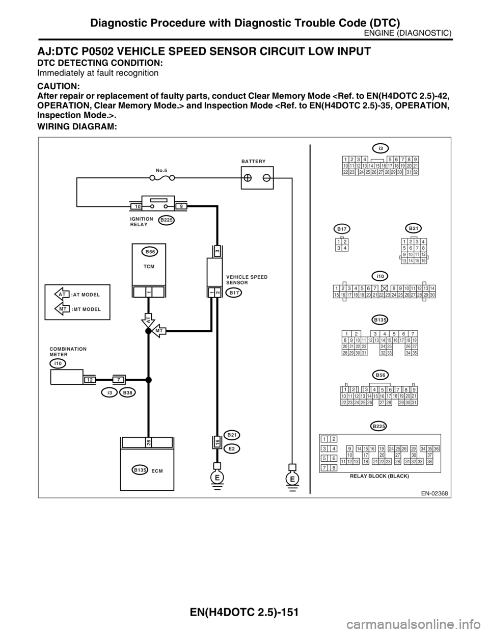
EN(H4DOTC 2.5)-151
ENGINE (DIAGNOSTIC)
Diagnostic Procedure with Diagnostic Trouble Code (DTC)
AJ:DTC P0502 VEHICLE SPEED SENSOR CIRCUIT LOW INPUT
DTC DETECTING CONDITION:
Immediately at fault recognition
CAUTION:
After repair or replacement of faulty parts, conduct Clear Memory Mode
OPERATION, Clear Memory Mode.> and Inspection Mode
Inspection Mode.>.
WIRING DIAGRAM:
EN-02368
i10
B135B21
123
4
56
78
9
1011 12
1314 15 16
B17
i3
567
82 1
94 310
24 22 23 2511 12 13 14 15
26 27
2816 17 18 19
20 21
29 30 31 32 33 34 35
E E
i10
B38
i3B17
E2 B21
B135B225 109
26
2
21
1
No.5
ECM
3
16
7
12
AT
:AT MODEL
MT
:MT MODEL
MT
AT
IGNITION
RELAYBATTERY
TCM
VEHICLE SPEED
SENSOR
COMBINATION
METERB56
3412
123456789101112131415161718192021222324252627282930
12
789 56 3
410 11 1219 20 21
29 30 31 13 14 15 1617
27 2818
22 23 24 25 26
B56
B225
RELAY BLOCK (BLACK)
10111213
1415161718
1920212223
2425262728
2930313233
3435363738
12
934
56
78
219
32
1234 5610 11 12 13 14 15716
23 3019 20
22 26 27 28 29817
24 3118
25
Page 2177 of 2870

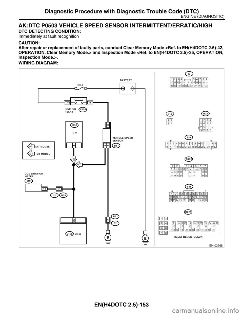
EN(H4DOTC 2.5)-153
ENGINE (DIAGNOSTIC)
Diagnostic Procedure with Diagnostic Trouble Code (DTC)
AK:DTC P0503 VEHICLE SPEED SENSOR INTERMITTENT/ERRATIC/HIGH
DTC DETECTING CONDITION:
Immediately at fault recognition
CAUTION:
After repair or replacement of faulty parts, conduct Clear Memory Mode
OPERATION, Clear Memory Mode.> and Inspection Mode
Inspection Mode.>.
WIRING DIAGRAM:
EN-02368
i10
B135B21
123
4
56
78
9
1011 12
1314 15 16
B17
i3
567
82 1
94 310
24 22 23 2511 12 13 14 15
26 27
2816 17 18 19
20 21
29 30 31 32 33 34 35
E E
i10
B38
i3B17
E2 B21
B135B225 109
26
2
21
1
No.5
ECM
3
16
7
12
AT
:AT MODEL
MT
:MT MODEL
MT
AT
IGNITION
RELAYBATTERY
TCM
VEHICLE SPEED
SENSOR
COMBINATION
METERB56
3412
123456789101112131415161718192021222324252627282930
12
789 56 3
410 11 1219 20 21
29 30 31 13 14 15 1617
27 2818
22 23 24 25 26
B56
B225
RELAY BLOCK (BLACK)
10111213
1415161718
1920212223
2425262728
2930313233
3435363738
12
934
56
78
219
32
1234 5610 11 12 13 14 15716
23 3019 20
22 26 27 28 29817
24 3118
25
Page 2182 of 2870
EN(H4DOTC 2.5)-158
ENGINE (DIAGNOSTIC)
Diagnostic Procedure with Diagnostic Trouble Code (DTC)
WIRING DIAGRAM:
EN-02364
B317
34
12
B22
125678
131415169101112
34
17181920
B21
123
4
56
78
9
1011 12
1314 15 16
B83
1
23456
B135
567
82 1
94 3
10
24 22 23 2511 12 13 14 15
26 27
2816 17 18 19
20 21
29 30 31 32 33 34 35
B:
B35D6
B135 B: C:
D4 D3
C18
B1 C35
D1 B4
D2
SBF-5
2
1
3
4
E
E57
3
6 4
1
2 2
3
15
16
E
5
EE
B137 D:ECM B309
B136
B122
1
E2 B21
E3 B22 B317
E56B47 35
2 1
4 3
D5C16C29
19122018
MAIN RELAYBATTERY
ELECTRONIC
THROTTLE
CONTROL ELECTRONIC
THROTTLE
CONTROL
RELAY
B83
B122
123456783412
56
B47
B137
567
82 1
94 3
10
22 23 11 12 13 14 15
24 25
2616 17
18 19 20 21
27 28 29 30 31
D:
B136
56
782 1
94 3
10
24 22 23 2511 12 13
1415
26 27
2816
17 18 19 20 21
33 34 29
32 30
31 35
C:
B309
34
12
E57