2004 SUBARU FORESTER automatic transmission
[x] Cancel search: automatic transmissionPage 2541 of 2870

4AT(H4SO)-82
AUTOMATIC TRANSMISSION (DIAGNOSTIC)
Diagnostic Procedure with Diagnostic Trouble Code (DTC)
Step Check Yes No
1 CHECK HARNESS CONNECTOR BETWEEN
TCM AND TRANSMISSION.
1) Turn the ignition switch to OFF.
2) Disconnect the connector from TCM and
transmission.
3) Measure the resistance of harness
between TCM and transmission connector.
Connector & terminal
(B55) No. 24 — (B11) No. 19:Is the resistance less than 1
Ω?Go to step 2.Repair the open
circuit in harness
between TCM and
transmission con-
nector.
2 CHECK HARNESS CONNECTOR BETWEEN
TCM AND TRANSMISSION.
Measure the resistance of harness between
TCM and transmission connector.
Connector & terminal
(B54) No. 19 — (B11) No. 20:Is the resistance less than 1
Ω?Go to step 3.Repair the open cir-
cuit in harness
between TCM and
transmission, and
poor contact in cou-
pling connector.
3 CHECK HARNESS CONNECTOR BETWEEN
TCM AND TRANSMISSION.
Measure the resistance of harness between
TCM and chassis ground.
Connector & terminal
(B55) No. 24 — Chassis ground:Is the resistance more than 1
MΩ?Go to step 4.Repair the short
circuit in harness
between TCM and
transmission con-
nector.
4 CHECK HARNESS CONNECTOR BETWEEN
TCM AND TRANSMISSION.
Measure the resistance of harness between
TCM and chassis ground.
Connector & terminal
(B54) No. 19 — Chassis ground:Is the resistance more than 1
MΩ?Go to step 5.Repair the short
circuit in harness
between TCM and
transmission con-
nector.
5 CHECK REAR VEHICLE SPEED SENSOR.
Measure the resistance between transmission
connector receptacle’s terminals.
Connector & terminal
(T4) No. 19 — No. 20:Is the resistance 450 — 650
Ω?Go to step 6.Replace the rear
vehicle speed sen-
sor.
Speed Sensor.>
6 PREPARE OSCILLOSCOPE.Do you have an oscilloscope? Go to step 10.Go to step 7.
7 PREPARE SUBARU SELECT MONITOR.Do you have a Subaru Select
Monitor?Go to step 9.Go to step 8.
8 CHECK INPUT SIGNAL FOR TCM.
1) Connect the connectors to TCM and trans-
mission.
2) Lift-up or raise the vehicle and place rigid
rack.
N
OTE:
Raise all wheels off floor.
3) Start the engine and set vehicle in 20 km/h
(12 MPH) condition.
N
OTE:
The speed difference between front and rear
wheels may light the ABS warning light, but this
indicates no malfunction. When AT control diag-
nosis is finished, perform the ABS memory
clearance procedure of on-board diagnostics
system.
4) Measure the voltage between TCM con-
nector terminals.
Connector & terminal
(B55) No. 24 (+) — (B54) No. 19 (
−):Is the voltage more than AC 1
V?Even if the
POWER indicator
light was blinking,
the circuit has
returned to a nor-
mal condition at
this time. A tempo-
rary poor contact
of the connector or
harness may be
the cause. Repair
the harness or
connector in TCM
and transmission.Go to step 11.
Page 2542 of 2870

4AT(H4SO)-83
AUTOMATIC TRANSMISSION (DIAGNOSTIC)
Diagnostic Procedure with Diagnostic Trouble Code (DTC)
9 CHECK INPUT SIGNAL FOR TCM USING
SUBARU SELECT MONITOR.
1) Connect the connectors to TCM and trans-
mission.
2) Connect the Subaru Select Monitor to data
link connector.
3) Lift-up or raise the vehicle and place rigid
rack.
N
OTE:
Raise all wheels off floor.
4) Turn the ignition switch to ON and turn Sub-
aru Select Monitor switch to ON.
5) Start the engine.
6) Read the data of vehicle speed using Sub-
aru Select Monitor.
Compare the speedometer with Subaru
Select Monitor indications.
Vehicle speed is indicated in “km/h” or
“MPH”.
7) Slowly increase the vehicle speed to 60 km/
h (37 MPH).
N
OTE:
The speed difference between front and rear
wheels may light the ABS warning light, but this
indicates no malfunction. When AT control diag-
nosis is finished, perform the ABS memory
clearance procedure of on-board diagnostics
system.
tion increase as the Subaru
Select Monitor data increases?Even if the
POWER indicator
light was blinking,
the circuit has
returned to a nor-
mal condition at
this time. A tempo-
rary poor contact
of the connector or
harness may be
the cause. Repair
the harness or
connector in TCM
and transmission.Go to step 11.
10 CHECK INPUT SIGNAL FOR TCM USING
OSCILLOSCOPE.
1) Connect the connectors to TCM and trans-
mission.
2) Lift-up or raise the vehicle and place rigid
rack.
NOTE:
Raise all wheels off floor.
3) Set the oscilloscope to TCM connector ter-
minals.
Connector & terminal
Positive probe; (B55) No. 24
Earth lead; (B54) No. 19
4) Start the engine and set vehicle in 20 km/h
(12 MPH) condition.
NOTE:
The speed difference between front and rear
wheels may light the ABS warning light, but this
indicates no malfunction. When AT control diag-
nosis is finished, perform the ABS memory
clearance procedure of on-board diagnostics
system.
5) Measure the signal voltage indicated on
oscilloscope.Is the signal voltage more than
AC 1 V?Even if the
POWER indicator
light was blinking,
the circuit has
returned to a nor-
mal condition at
this time. A tempo-
rary poor contact
of the connector or
harness may be
the cause. Repair
the harness or
connector in TCM
and transmission.Go to step 11.
11 CHECK POOR CONTACT.Is there poor contact in rear
vehicle speed sensor circuit?Repair the poor
contact.Replace the TCM.
trol Module
(TCM).> Step Check Yes No
Page 2543 of 2870

4AT(H4SO)-84
AUTOMATIC TRANSMISSION (DIAGNOSTIC)
Diagnostic Procedure without Diagnostic Trouble Code (DTC)
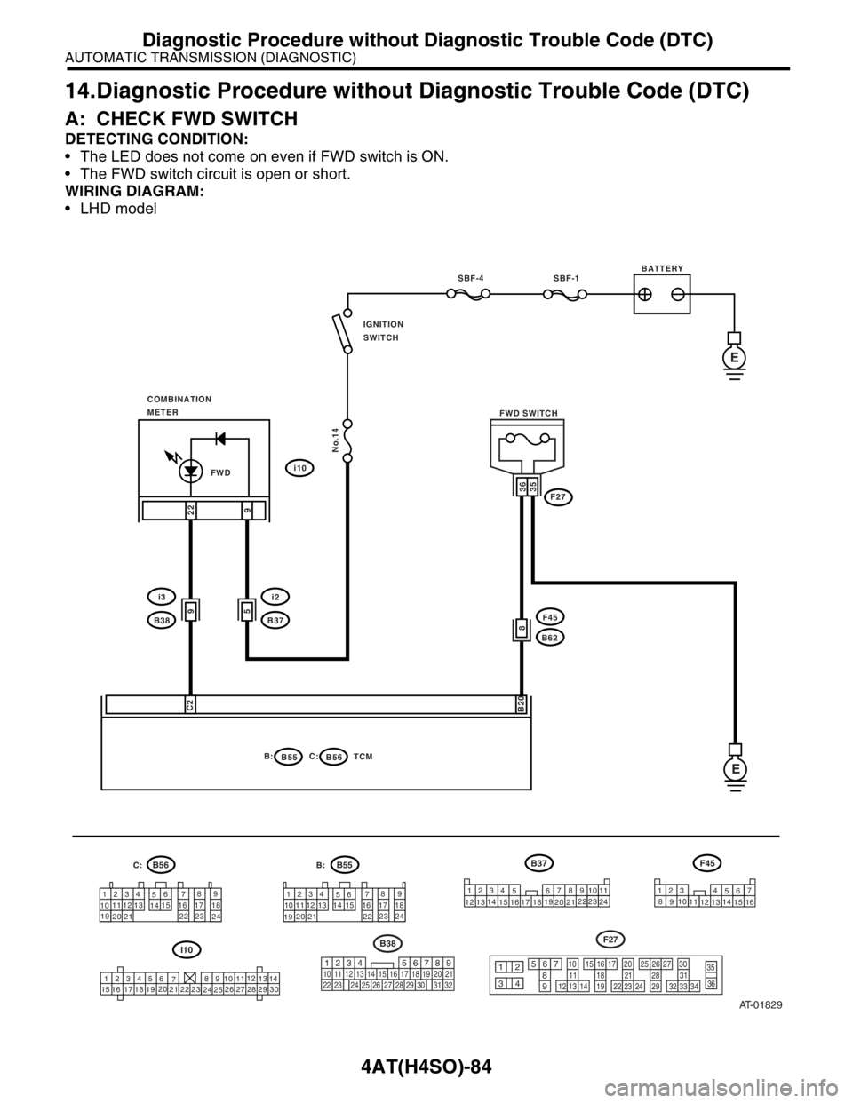
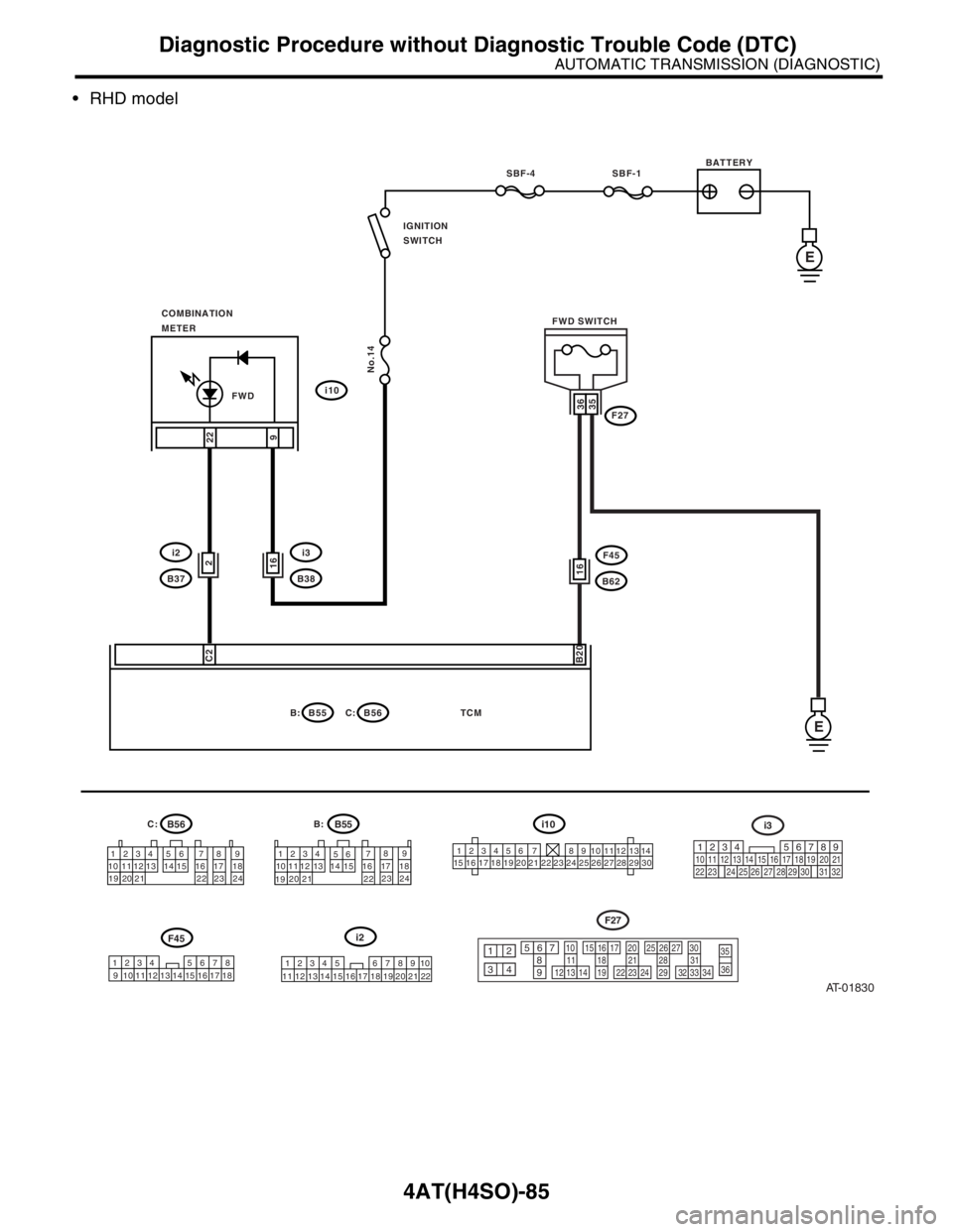
14.Diagnostic Procedure without Diagnostic Trouble Code (DTC)
A: CHECK FWD SWITCH
DETECTING CONDITION:
The LED does not come on even if FWD switch is ON.
The FWD switch circuit is open or short.
WIRING DIAGRAM:
LHD model
AT-01829
BATTERY
1234
56789
10 1112
13 14 15 16 17 18
192021
2223 241234
56789
101112
13
1415 16 17 18
19
202122 23
24
123456
78 9 10 1112
13
14
15 16 17
181920
21
2223
24
2526
272829
30
1234
578
910112324
121314
156
16 17 1819
20 2122
SBF-4 SBF-1
No.14
IGNITION
SWITCH
FWDi10
i2
B37
B55 B:B56TCM C:
F45
B62
F27
22
9
36
8
35
C2
B20
COMBINATION
METER
E
E
FWD SWITCH
59
i3
B38
123 4
57
8
91011
121314
156
16
219
32
B38
1234
5610 11 12 13 14 15716
23 3019 20
22 26 27 28 29817
24 3118
2556789
1011121314
1516171819
2021222324
252627282936
3512
34
3031323334
F27
B55 B56
i10B37F45B:
C:
Page 2544 of 2870

4AT(H4SO)-85
AUTOMATIC TRANSMISSION (DIAGNOSTIC)
Diagnostic Procedure without Diagnostic Trouble Code (DTC)
RHD model
AT-01830
BATTERY
1234
56789
10 1112
13 14 15 16 17 18
192021
2223 241234 5 6 7 8 9
10 11 12 13 14 15 16 17 18
19 20 21 22 23 24123456 7 891011121314
15 16 17 18 19 20 21 22 23 24 25 26 27 28 29 30
SBF-4 SBF-1
No.14
IGNITION
SWITCH
i10
i3
B38
B55 B:B56TCM
C:
F45
B62
F27
22
9
36
16
35
C2
B20
COMBINATION
METER
E
E
FWD SWITCH
1234 5 678910
11 12 13 14 15 16 17 18 19 20 21 221234567812 13 14 15 16 17 1891011
1
219
32
i3
1234
5610 11 12 13 14 15716
23 3019 20
22 26 27 28 29817
24 3118
25
56789
1011121314
1516171819
2021222324
252627282936
3512
34
3031323334
F27
i10
i2
F45
162i2
B37
FWD
B55B:B56C:
Page 2545 of 2870

4AT(H4SO)-86
AUTOMATIC TRANSMISSION (DIAGNOSTIC)
Diagnostic Procedure without Diagnostic Trouble Code (DTC)
Step Check Yes No
1 CHECK FWD SWITCH.
Connect the Subaru Select Monitor to data link
connector, and then change to LED display
screen.When the fuse is inserted to
FWD switch, does LED light
up?Go to step CHECK
BRAKE SWITCH.
CHECK BRAKE
SWITCH, Diag-
nostic Procedure
without Diagnostic
Trouble Code
(DTC).>Go to step 2.
2 CHECK FWD INDICATOR LIGHT.
1) Turn the ignition switch to OFF.
2) Disconnect the TCM connector.
3) Turn the ignition switch to ON.
4) Short the combination meter connector to
chassis ground.
CAUTION:
Be sure to short through fuse.
Connector & terminal
(i10) No. 22 — Chassis ground:Does the FWD indicator light
illuminate?Go to step 3.Inspect the combi-
nation meter.
Meter Assembly.>
3 CHECK HARNESS CONNECTOR BETWEEN
TCM AND FWD SWITCH.
1) Turn the ignition switch to OFF.
2) Disconnect the connector from TCM and
FWD switch.
3) Measure the resistance of harness
between TCM and FWD switch connector.
Connector & terminal
(B55) No. 20 — (F27) No. 36:Is the resistance less than 1
Ω?Go to step 4.Repair the open
circuit in harness
between TCM and
FWD switch con-
nector.
4 CHECK HARNESS CONNECTOR BETWEEN
TCM AND FWD SWITCH.
Measure the resistance of harness connector
between TCM and body to make sure that cir-
cuit does not short.
Connector & terminal
(B55) No. 20 — Chassis ground:Is the resistance more than 1
MΩ?Go to step 5.Repair the short
circuit in harness
between TCM and
FWD switch con-
nector.
5 CHECK HARNESS CONNECTOR BETWEEN
FWD SWITCH AND CHASSIS GROUND.
Measure the resistance of harness between
FWD switch and chassis ground.
Connector & terminal
(F27) No. 35 — Chassis ground:Is the resistance less than 1
Ω?Go to step 6.Repair the open
circuit in harness
between FWD
switch connector
and chassis
ground.
6 CHECK INPUT SIGNAL FOR TCM.
1) Turn the ignition switch to OFF.
2) Connect the connector to TCM and FWD
switch.
3) Turn the ignition switch to ON.
4) Measure the signal voltage for TCM while
installing the fuse to FWD switch connector.
Connector & terminal
(B55) No. 20 (+) — Chassis ground (
−):Is the voltage less than 1 V? Go to step 7.Go to step 11.
7 CHECK INPUT SIGNAL FOR TCM.
Measure the signal voltage for TCM while
removing the fuse from FWD switch connector.
Connector & terminal
(B55) No. 20 (+) — Chassis ground (
−):Is the voltage 6 — 9.1 V? Go to step 8.Replace the TCM.
trol Module
(TCM).>
Page 2546 of 2870

4AT(H4SO)-87
AUTOMATIC TRANSMISSION (DIAGNOSTIC)
Diagnostic Procedure without Diagnostic Trouble Code (DTC)
8 CHECK HARNESS CONNECTOR BETWEEN
TCM AND COMBINATION METER.
1) Turn the ignition switch to OFF.
2) Disconnect the connector from TCM and
combination meter.
3) Measure the resistance of harness
between TCM and combination meter.
Connector & terminal
(B56) No. 2 — (i11) No. 4:Is the resistance less than 1
Ω?Go to step 9.Repair the open
circuit in harness
between TCM and
combination meter
and poor contact
in coupling con-
nector.
9 CHECK HARNESS CONNECTOR BETWEEN
TCM AND COMBINATION METER.
Measure the resistance of harness connector
between TCM and chassis ground.
Connector & terminal
(B56) No. 2 — Chassis ground:Is the resistance more than 1
MΩ?Go to step 10.Repair the short
circuit in harness
between TCM and
combination meter
connector.
10 CHECK OUTPUT SIGNAL EMITTED FROM
TCM.
1) Turn the ignition switch to OFF.
2) Connect the connector to TCM and combi-
nation meter.
3) Turn the ignition switch to ON.
4) Measure the signal voltage for TCM while
installing the fuse to FWD switch connector.
Connector & terminal
(B56) No. 2 (+) — Chassis ground (
−):Is the voltage less than 1 V? Go to step 11.Go to step 12.
11 CHECK OUTPUT SIGNAL EMITTED FROM
TCM.
Measure the signal voltage for TCM while
removing the fuse from FWD switch connector.
Connector & terminal
(B56) No. 2 (+) — Chassis ground (
−):Is the voltage 6 — 9.1 V? Go to step 12.Replace the TCM.
trol Module
(TCM).>
12 CHECK POOR CONTACT.Is there poor contact in FWD
switch circuit?Repair the poor
contact.Replace the TCM.
trol Module
(TCM).> Step Check Yes No
Page 2547 of 2870

4AT(H4SO)-88
AUTOMATIC TRANSMISSION (DIAGNOSTIC)
Diagnostic Procedure without Diagnostic Trouble Code (DTC)
B: CHECK BRAKE SWITCH
C: CHECK ABS SWITCH
D: CHECK CRUISE CONTROL SWITCH
Step Check Yes No
1 CHECK BRAKE SWITCH.When the brake pedal is
depressed, does LED light up?Go to step CHECK
ABS SWITCH.
CHECK CRUISE
CONTROL
SWITCH, Diag-
nostic Procedure
without Diagnostic
Trouble Code
(DTC).>Check the brake
switch circuit.
DTC P0703
TORQUE CON-
VERTER/BRAKE
SWITCH “B” CIR-
CUIT, Diagnostic
Procedure with
Diagnostic Trou-
ble Code (DTC).>
Step Check Yes No
1 CHECK ABS SWITCH.Does the LED of ABS switch
light up?Check the ABS
switch circuit.
CONTROL (NON
CONTROLLED),
Diagnostics Proce-
dure with Diagnos-
tic Trouble Code
(DTC).>
ABS-AT CON-
TROL (CON-
TROLLED),
Diagnostics Proce-
dure with Diagnos-
tic Trouble Code
(DTC).>Go to step CHECK
CRUISE CON-
TROL SWITCH.
CHECK CRUISE
CONTROL
SWITCH, Diag-
nostic Procedure
without Diagnostic
Trouble Code
(DTC).>
Step Check Yes No
1 CHECK CRUISE CONTROL SWITCH.When the cruise control is set,
does LED light up?Go to step CHECK
KICK-DOWN
SWITCH.
CHECK KICK–
DOWN SWITCH,
Diagnostic Proce-
dure without Diag-
nostic Trouble
Code (DTC).>Check the cruise
control.
Diagnostic Proce-
dure with Diagnos-
tic Trouble Code
(DTC).>
Page 2548 of 2870

4AT(H4SO)-89
AUTOMATIC TRANSMISSION (DIAGNOSTIC)
Diagnostic Procedure without Diagnostic Trouble Code (DTC)
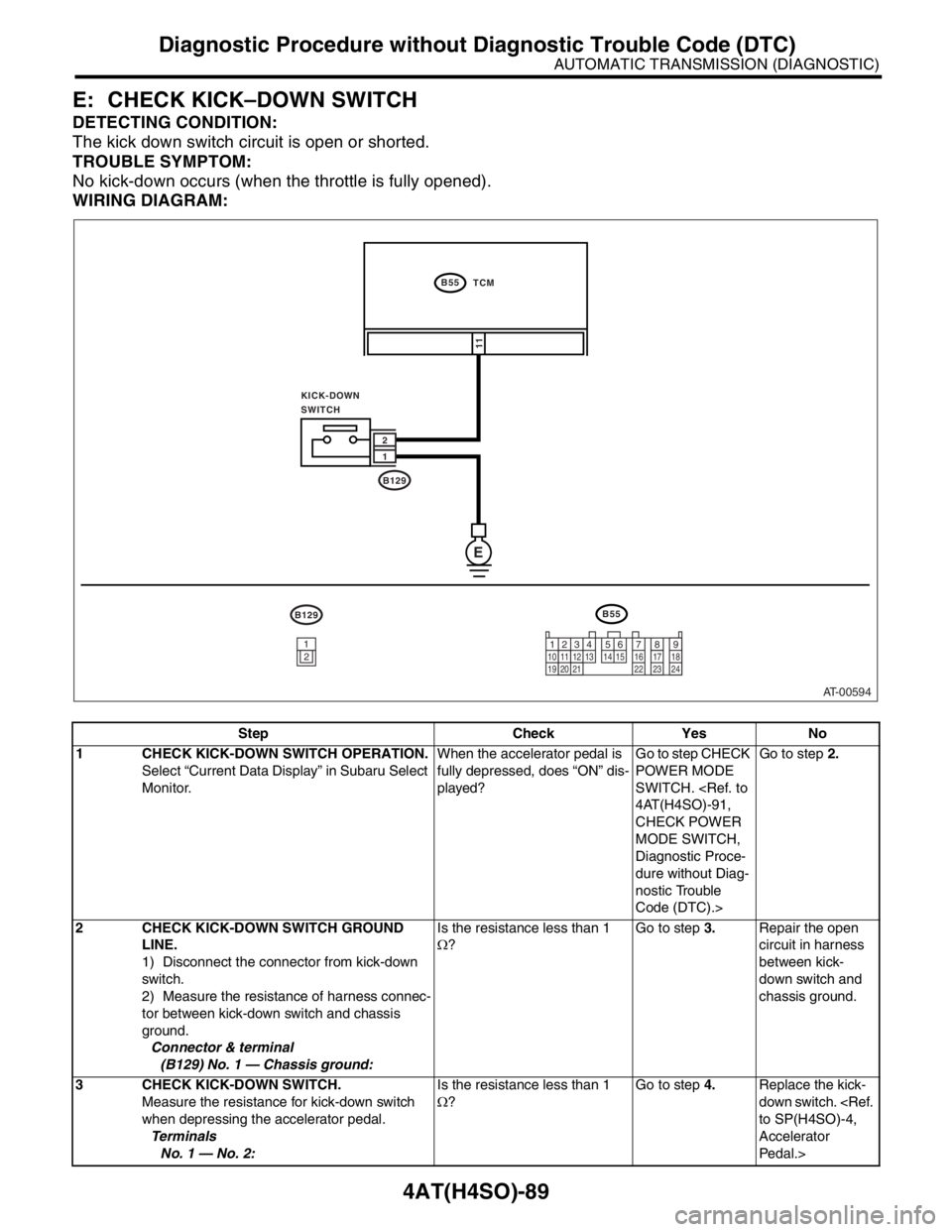
E: CHECK KICK–DOWN SWITCH
DETECTING CONDITION:
The kick down switch circuit is open or shorted.
TROUBLE SYMPTOM:
No kick-down occurs (when the throttle is fully opened).
WIRING DIAGRAM:
Step Check Yes No
1 CHECK KICK-DOWN SWITCH OPERATION.
Select “Current Data Display” in Subaru Select
Monitor.When the accelerator pedal is
fully depressed, does “ON” dis-
played?Go to step CHECK
POWER MODE
SWITCH.
CHECK POWER
MODE SWITCH,
Diagnostic Proce-
dure without Diag-
nostic Trouble
Code (DTC).>Go to step 2.
2 CHECK KICK-DOWN SWITCH GROUND
LINE.
1) Disconnect the connector from kick-down
switch.
2) Measure the resistance of harness connec-
tor between kick-down switch and chassis
ground.
Connector & terminal
(B129) No. 1 — Chassis ground:Is the resistance less than 1
Ω?Go to step 3.Repair the open
circuit in harness
between kick-
down switch and
chassis ground.
3 CHECK KICK-DOWN SWITCH.
Measure the resistance for kick-down switch
when depressing the accelerator pedal.
Te r m i n a l s
No. 1 — No. 2:Is the resistance less than 1
Ω?Go to step 4.Replace the kick-
down switch.
Accelerator
Pedal.>
AT-00594
E
B55
B55 TCM
KICK-DOWN
SWITCH
B129 1 2
B129
11
1
23410 11 12
19
20 21135614 1578916 17 18
22 23 241
2