Page 1105 of 2870

EN(H4SO)-7
ENGINE (DIAGNOSTIC)
General Description
The antenna feeder must be placed as far
apart as possible from the ECM and MFI har-
ness.
Carefully adjust the antenna for correct
matching.
When mounting a large power type radio, pay
special attention to the three items above men-
tioned.
Incorrect installation of the radio may affect
the operation of the ECM.
13) Before disconnecting the fuel hose, disconnect
the fuel pump connector and crank the engine for
more than five seconds to release pressure in the
fuel system. If engine starts during this operation,
run it until it stops.
14) Problems in the electronic-controlled automatic
transmission may be caused by failure of the en-
gine, the electronic control system, the transmis-
sion proper, or by a combination of these. These
three causes must be distinguished clearly when
performing diagnostics.
15) Diagnostics should be conducted by rotating
with simple, easy operations and proceeding to
complicated, difficult operations. The most impor-
tant thing in diagnostics is to understand the cus-
tomer’s complaint, and distinguish between the
three causes.
16) In AT models, do not continue the stall for more
than five seconds. (from closed throttle, fully open
throttle to stall engine speed.)
17) On the model with ABS, when performing driv-
ing test in jacked-up or lifted-up position, some-
times the warning light may be lit, but this is not a
malfunction of the system. The reason for this is the
speed difference between the front and rear
wheels. After diagnosis of engine control system,
perform the ABS memory clearance procedure of
self-diagnosis function.
B: INSPECTION
Before performing diagnostics, check the following
items which might affect engine problems:
1. BATTERY
1) Measure battery voltage and specific gravity of
electrolyte.
Standard voltage: 12 V
Specific gravity: Above 1.260
2) Check the condition of the main and other fuses,
and harnesses and connectors. Also check for
proper grounding.
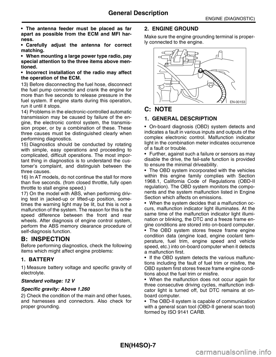
2. ENGINE GROUND
Make sure the engine grounding terminal is proper-
ly connected to the engine.
C: NOTE
1. GENERAL DESCRIPTION
On-board diagnosis (OBD) system detects and
indicates a fault in various inputs and outputs of the
complex electronic control. Malfunction indicator
light in the combination meter indicates occurrence
of a fault or trouble.
Further, against such a failure or sensors as may
disable the drive, the fail-safe function is provided
to ensure the minimal driveability.
The OBD system incorporated with the vehicles
within this engine family complies with Section
1968.1, California Code of Regulations (OBD-II
regulation). The OBD system monitors the compo-
nents and the system malfunction listed in Engine
Section which affects on emissions.
When the system decides that a malfunction oc-
curs, malfunction indicator light illuminates. At the
same time of the malfunction indicator light illumi-
nation or blinking, the DTC and a freeze frame en-
gine conditions are stored into on-board computer.
The OBD system stores freeze frame engine
condition data (engine load, engine coolant tem-
perature, fuel trim, engine speed and vehicle
speed, etc.) into on-board computer when it detects
a malfunction first.
If the OBD system detects the various malfunc-
tions including the fault of fuel trim or misfire, the
OBD system first stores freeze frame engine condi-
tions about the fuel trim or misfire.
When the malfunction does not occur again for
three consecutive driving cycles, malfunction indi-
cator light is turned off, but DTC remains at on-
board computer.
The OBD-II system is capable of communication
with a general scan tool (OBD-II general scan tool)
formed by ISO 9141 CARB.
EN-00153
Page 1106 of 2870

EN(H4SO)-8
ENGINE (DIAGNOSTIC)
General Description
The OBD-II diagnostics procedure is different
from the usual diagnosis procedure. When trouble-
shooting the OBD-II models, connect Subaru Se-
lect Monitor or the OBD-II general scan tool to the
vehicle.
2. ENGINE AND EMISSION CONTROL SYS-
TEM
MFI system is a system that supplies the opti-
mum air-fuel mixture to the engine for all the vari-
ous operating conditions through the use of the
latest electronic technology.
With this system fuel, which is pressurized at a con-
stant pressure, is injected into the intake air pas-
sage of the cylinder head. The injection quantity of
fuel is controlled by an intermittent injection system
where the electro-magnetic injection valve (fuel in-
jector) opens only for a short period of time, de-
pending on the quantity of air required for one cycle
of operation. In actual operation, the injection quan-
tity is determined by the duration of an electric sig-
nal applied to the fuel injector and this permits
simple, yet highly precise metering of the fuel.
Further, all the operating conditions of the engine
are converted into electric signals, and this results
in additional features of the system, such as large
improved adaptability, easier addition of compen-
sating element, etc.The MFI system also has the following features:
Reduced emission of harmful exhaust gases.
Reduced in fuel consumption.
Increased engine output.
Superior acceleration and deceleration.
Excellent engine start and warm-up perfor-
mance by the correction of engine coolant tem-
perature and intake air temperature.3. AUTOMATIC TRANSMISSION AND
ELECTRONIC-HYDRAULIC CONTROL SYS-
TEM
The electronic-hydraulic control system consists of
various sensors and switches, TCM and the hy-
draulic controller including solenoid valves. The
system controls the transmission body including
shift control, lock-up control, overrunning clutch
control, line pressure control and shift timing con-
trol. It also controls the AWD transfer clutch. In oth-
er words, the system detects various operating
conditions from various input signals and sends
output signals to shift solenoids 1, 2 and low clutch
timing solenoid and 2-4 brake timing solenoid, line
pressure duty solenoid, lock-up duty solenoid,
transfer duty solenoid and 2-4 brake duty solenoid
(a total of eight solenoids).
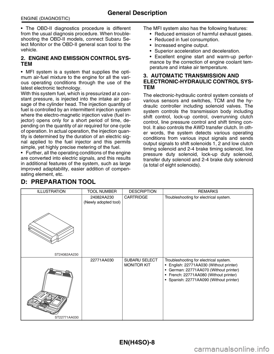
D: PREPARATION TOOL
ILLUSTRATION TOOL NUMBER DESCRIPTION REMARKS
24082AA230
(Newly adopted tool)CARTRIDGE Troubleshooting for electrical system.
22771AA030 SUBARU SELECT
MONITOR KITTroubleshooting for electrical system.
English: 22771AA030 (Without printer)
German: 22771AA070 (Without printer)
French: 22771AA080 (Without printer)
Spanish: 22771AA090 (Without printer)
ST24082AA230
ST22771AA030
Page 1107 of 2870
EN(H4SO)-9
ENGINE (DIAGNOSTIC)
Electrical Component Location
4. Electrical Component Location
A: LOCATION
1. ENGINE
CONTROL MODULE
LHD MODEL
RHD MODEL
(1) Engine control module (ECM) (3) Test mode connector (4) Data link connector
(2) Malfunction indicator light
EN-00240 (1)
(2) (3) (4)
EN-00241 (2)
(3)(4)
(1)
Page 1108 of 2870
EN(H4SO)-10
ENGINE (DIAGNOSTIC)
Electrical Component Location
(1)
EN-00156(2)EN-00157
(3)
EN-00158(4)EN-00236
Page 1109 of 2870
EN(H4SO)-11
ENGINE (DIAGNOSTIC)
Electrical Component Location
SENSOR
EN-02379
(1)(2)
(3)(4)
(5)
(6) (7)(8)
(1) Intake air temperature sensor (4) Throttle position sensor (8) Engine coolant temperature sen-
sor (with AT warmer)
(2) Manifold absolute pressure sensor (5) Knock sensor
(3) Engine coolant temperature sen-
sor (without AT warmer)(6) Camshaft position sensor
(7) Crankshaft position sensor
Page 1110 of 2870
EN(H4SO)-12
ENGINE (DIAGNOSTIC)
Electrical Component Location
(1)
EN-00006
(2)
EN-00160
EN-00008 (3)EN-00161 (4)
EN-00010
(5)
EN-00011
(6)
EN-00012
(7)
EN-02380
(8)
Page 1111 of 2870
EN(H4SO)-13
ENGINE (DIAGNOSTIC)
Electrical Component Location
EN-00162
(2)
(3) (1)
(4)
(1) Front oxygen (A/F) sensor (3) Front catalytic converter (4) Rear catalytic converter
(2) Rear oxygen sensor
EN-00014
(1)
EN-00163 (2)
EN-00016
(3)
EN-00164 (4)
Page 1112 of 2870
EN(H4SO)-14
ENGINE (DIAGNOSTIC)
Electrical Component Location
LHD MODEL
RHD MODEL
(1) Fuel level sensor (2) Fuel sub level sensor
EN-00242
(1)
(2)
EN-00243
(1)
(2)
EN-00244
(1)
EN-00246 (2)