2004 SUBARU FORESTER check oil
[x] Cancel search: check oilPage 2661 of 2870

4AT(H4DOTC)-85
AUTOMATIC TRANSMISSION (DIAGNOSTIC)
Diagnostic Procedure with Diagnostic Trouble Code (DTC)
8 CHECK OUTPUT SIGNAL FROM TCM US-
ING SUBARU SELECT MONITOR.
1) Shift the select lever to “1” range.
2) Read the data of low & reverse duty sole-
noid.Is the value 61.5%? Even if the POWER
indicator light was
blinking, the circuit
has returned to a
normal condition at
this time. A tempo-
rary poor contact of
the connector or
harness may be the
cause. Repair the
harness or connec-
tor in TCM and
transmission.Go to step 9.
9 CHECK POOR CONTACT.Is there poor contact in low &
reverse duty solenoid circuit?Repair the poor
contact.Replace the TCM.
trol Module
(TCM).>
10 CHECK LOW & REVERSE BRAKE DUTY
SOLENOID (IN TRANSMISSION).
1) Remove the transmission connector from
bracket.
2) Drain the ATF.
CAUTION:
Do not drain the ATF until it cools down.
3) Remove the oil pan, and disconnect con-
nector from low & reverse brake duty solenoid.
4) Measure the resistance between low &
reverse brake duty solenoid connector and
transmission ground.
Connector & terminal
(AT12) No. 1 — Transmission ground:Is the resistance 2.0 — 4.5 Ω? Go to step 11.Replace the control
valve body.
Valve Body.>
11 CHECK HARNESS CONNECTOR BETWEEN
TRANSMISSION AND LOW & REVERSE
BRAKE DUTY SOLENOID.
Measure the resistance of harness between
low & reverse brake duty solenoid and trans-
mission connector.
Connector & terminal
(T4) No. 6 — (AT12) No. 1:Is the resistance less than 1
Ω?Go to step 12.Repair the open
circuit in harness
between low &
reverse brake duty
solenoid and
transmission con-
nector.
12 CHECK HARNESS CONNECTOR BETWEEN
TRANSMISSION AND LOW & REVERSE
BRAKE DUTY SOLENOID.
Measure the resistance of harness between
transmission connector and transmission
ground.
Connector & terminal
(T4) No. 6 — Transmission ground:Is the resistance more than 1
MΩ?Even if the POWER
indicator light was
blinking, the circuit
has returned to a
normal condition at
this time. A tempo-
rary poor contact of
the connector or
harness may be the
cause. Repair the
harness or connec-
tor in low & reverse
brake duty solenoid
and transmission.Repair the short
circuit in harness
between low &
reverse brake duty
solenoid and
transmission con-
nector. Step Check Yes No
Page 2713 of 2870

MANUAL TRANSMISSION AND
DIFFERENTIAL
5MT
Page
1. General Description ....................................................................................2
2. Transmission Gear Oil ..............................................................................31
3. Manual Transmission Assembly ...............................................................32
4. Transmission Mounting System ................................................................39
5. Oil Seal......................................................................................................41
6. Differential Side Retainer Oil Seal.............................................................42
7. Switches and Harness ..............................................................................43
8. Vehicle Speed Sensor...............................................................................46
9. Preparation for Overhaul ...........................................................................47
10. Oil Pump ...................................................................................................48
11. Transfer Case and Extension Case Assembly..........................................50
12. Transfer Drive Gear ..................................................................................54
13. Transfer Driven Gear ................................................................................56
14. Center Differential .....................................................................................58
15. Reverse Check Sleeve..............................................................................59
16. Transmission Case ...................................................................................62
17. Main Shaft Assembly For Single-Range ...................................................69
18. Main Shaft Assembly For Dual-Range ......................................................77
19. Input Shaft Assembly ................................................................................83
20. Drive Pinion Shaft Assembly .....................................................................87
21. Front Differential Assembly .......................................................................96
22. Speedometer Gear..................................................................................103
23. Reverse Idler Gear ..................................................................................104
24. Shifter Fork and Rod ...............................................................................106
25. Counter Gear ..........................................................................................109
26. General Diagnostic..................................................................................111
Page 2725 of 2870
5MT-13
MANUAL TRANSMISSION AND DIFFERENTIAL
General Description
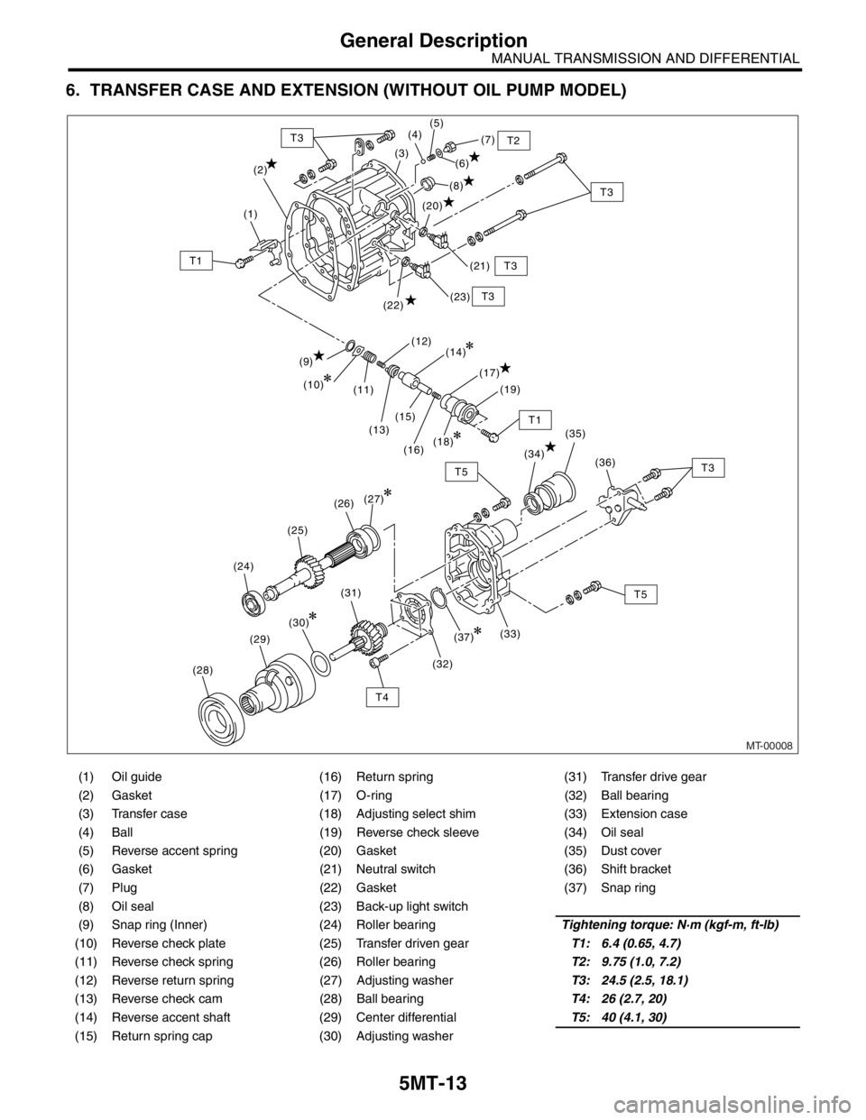
6. TRANSFER CASE AND EXTENSION (WITHOUT OIL PUMP MODEL)
(1) Oil guide (16) Return spring (31) Transfer drive gear
(2) Gasket (17) O-ring (32) Ball bearing
(3) Transfer case (18) Adjusting select shim (33) Extension case
(4) Ball (19) Reverse check sleeve (34) Oil seal
(5) Reverse accent spring (20) Gasket (35) Dust cover
(6) Gasket (21) Neutral switch (36) Shift bracket
(7) Plug (22) Gasket (37) Snap ring
(8) Oil seal (23) Back-up light switch
(9) Snap ring (Inner) (24) Roller bearingTightening torque: N·m (kgf-m, ft-lb)
(10) Reverse check plate (25) Transfer driven gearT1: 6.4 (0.65, 4.7)
(11) Reverse check spring (26) Roller bearingT2: 9.75 (1.0, 7.2)
(12) Reverse return spring (27) Adjusting washerT3: 24.5 (2.5, 18.1)
(13) Reverse check cam (28) Ball bearingT4: 26 (2.7, 20)
(14) Reverse accent shaft (29) Center differentialT5: 40 (4.1, 30)
(15) Return spring cap (30) Adjusting washer
MT-00008
(2)(7)
(6)
(21) (8) (5)
(4)
(3)
(1)
T3 T2
T3
T3
T1
T1
(20)
(9)
(11)
(13)(15) (10)(12)
(17)
(16)(19)
(22)(23)
(14)
(18)
T3
T5
T4(34)
(36) (35)
(33) (27)
(31)(30)
(29)
(28)
(37)
(32)
(24)(25)(26)
T3T5
Page 2726 of 2870
5MT-14
MANUAL TRANSMISSION AND DIFFERENTIAL
General Description
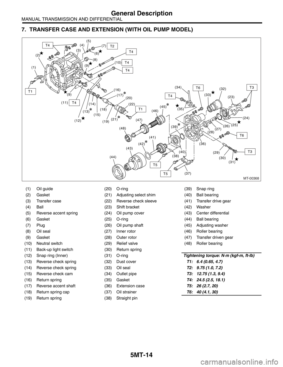
7. TRANSFER CASE AND EXTENSION (WITH OIL PUMP MODEL)
(1) Oil guide (20) O-ring (39) Snap ring
(2) Gasket (21) Adjusting select shim (40) Ball bearing
(3) Transfer case (22) Reverse check sleeve (41) Transfer drive gear
(4) Ball (23) Shift bracket (42) Washer
(5) Reverse accent spring (24) Oil pump cover (43) Center differential
(6) Gasket (25) O-ring (44) Ball bearing
(7) Plug (26) Oil pump shaft (45) Adjusting washer
(8) Oil seal (27) Inner rotor (46) Roller bearing
(9) Gasket (28) Outer rotor (47) Transfer driven gear
(10) Neutral switch (29) Relief valve (48) Roller bearing
(11) Back-up light switch (30) Return spring
(12) Snap ring (Inner) (31) O-ringTightening torque: N·m (kgf-m, ft-lb)
(13) Reverse check spring (32) Dust coverT1: 6.4 (0.65, 4.7)
(14) Reverse check spring (33) Oil sealT2: 9.75 (1.0, 7.2)
(15) Reverse check cam (34) Outlet pipeT3: 12.75 (1.3, 9.4)
(16) Return spring (35) GasketT4: 24.5 (2.5, 18.1)
(17) Reverse accent shaft (36) Extension caseT5: 26 (2.7, 20)
(18) Return spring cap (37) Oil strainerT6: 40 (4.1, 30)
(19) Return spring (38) Straight pin
MT-00368
(2)(7)
(6)
(10) (8) (5)
(4)
(3)
(1)
T4
T4
T2
T4
T4
(11)
T4
T4
T3
T3
T6
T6
T5
T5
T1
T1
(9)
(12)(14)
(15)(18)
(13)(16)
(20)
(19)(22)
(33)
(23)
(24) (32)
(25)
(26)
(27)
(28)
(36)
(31) (30) (29)
(37)
(35)
(9)(17)
(45)
(41)
(42)
(43)
(44)
(39)
(38)(40)
(21)
(48)(47)(46)(34)
Page 2743 of 2870
5MT-31
MANUAL TRANSMISSION AND DIFFERENTIAL
Transmission Gear Oil
2. Transmission Gear Oil
A: INSPECTION
1) Park the vehicle on a level surface.
2) Turn the ignition switch to OFF, and wait until the
engine cools.
3) Remove the oil level gauge and wipe it clean.
4) Reinsert the level gauge all the way. Be sure that
the level gauge is correctly inserted and in the
proper direction.
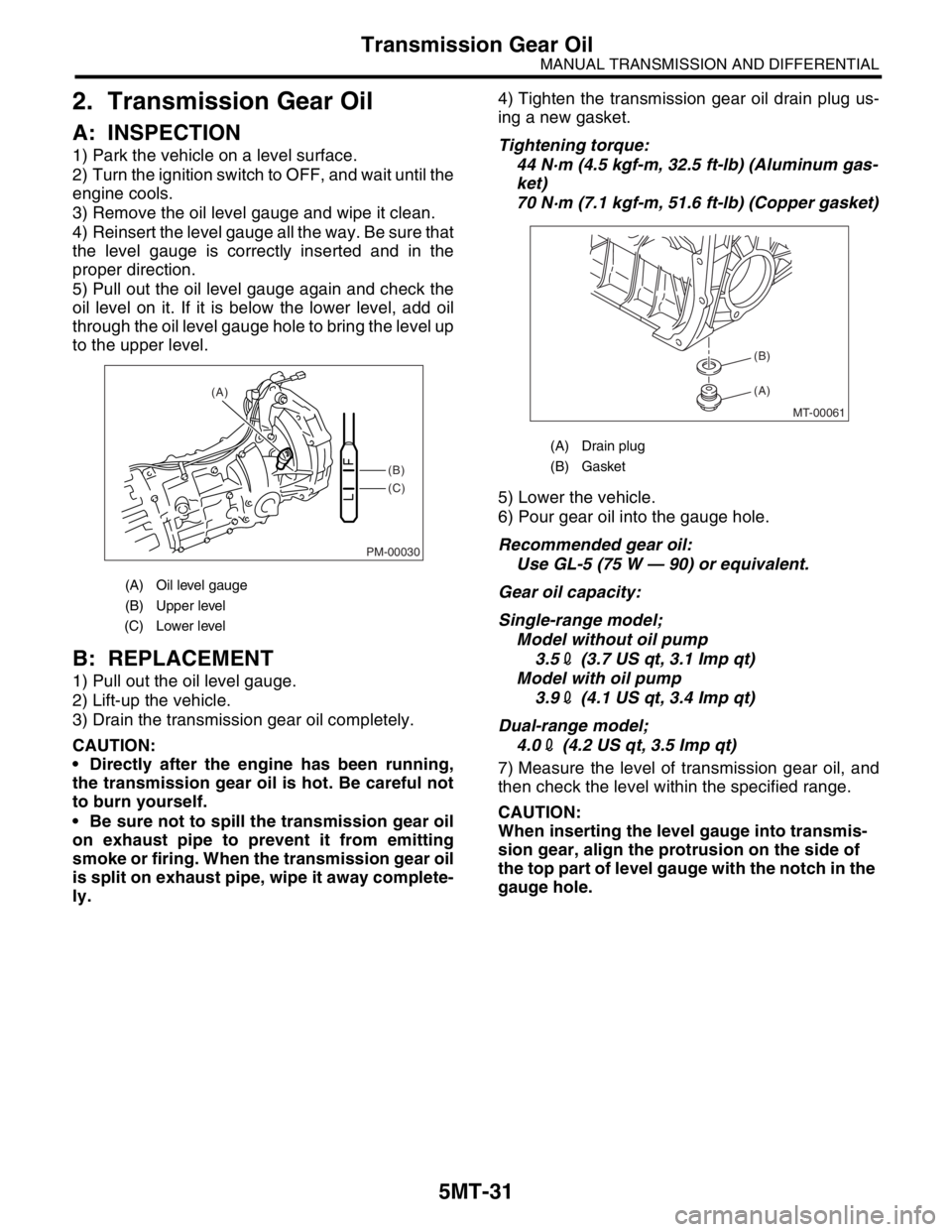
5) Pull out the oil level gauge again and check the
oil level on it. If it is below the lower level, add oil
through the oil level gauge hole to bring the level up
to the upper level.
B: REPLACEMENT
1) Pull out the oil level gauge.
2) Lift-up the vehicle.
3) Drain the transmission gear oil completely.
CAUTION:
Directly after the engine has been running,
the transmission gear oil is hot. Be careful not
to burn yourself.
Be sure not to spill the transmission gear oil
on exhaust pipe to prevent it from emitting
smoke or firing. When the transmission gear oil
is split on exhaust pipe, wipe it away complete-
ly.4) Tighten the transmission gear oil drain plug us-
ing a new gasket.
Tightening torque:
44 N·m (4.5 kgf-m, 32.5 ft-lb) (Aluminum gas-
ket)
70 N·m (7.1 kgf-m, 51.6 ft-lb) (Copper gasket)
5) Lower the vehicle.
6) Pour gear oil into the gauge hole.
Recommended gear oil:
Use GL-5 (75 W — 90) or equivalent.
Gear oil capacity:
Single-range model;
Model without oil pump
3.52 (3.7 US qt, 3.1 Imp qt)
Model with oil pump
3.92 (4.1 US qt, 3.4 Imp qt)
Dual-range model;
4.02 (4.2 US qt, 3.5 Imp qt)
7) Measure the level of transmission gear oil, and
then check the level within the specified range.
CAUTION:
When inserting the level gauge into transmis-
sion gear, align the protrusion on the side of
the top part of level gauge with the notch in the
gauge hole.
(A) Oil level gauge
(B) Upper level
(C) Lower level
PM-00030
(B)
(C) (A)
(A) Drain plug
(B) Gasket
MT-00061
(A) (B)
Page 2753 of 2870
5MT-41
MANUAL TRANSMISSION AND DIFFERENTIAL
Oil Seal
5. Oil Seal
A: INSPECTION
Check the oil seal portion for leakage. If leakage is
found, replace the oil seal with a new one.
B: REPLACEMENT
1) Clean the transmission exterior.
2) Drain the gear oil completely.
3) Replace the gasket with a new one, and then
tighten the drain plug after draining gear oil.
Tightening torque:
44 N·m (4.5 kgf-m, 32.5 ft-lb) (Aluminum gas-
ket)
70 N·m (7.1 kgf-m, 51.6 ft-lb) (Copper gasket)
4) Remove the rear exhaust pipe and muffler.
5) Remove the heat shield cover. (If equipped mod-
el)
6) Remove the propeller shaft.
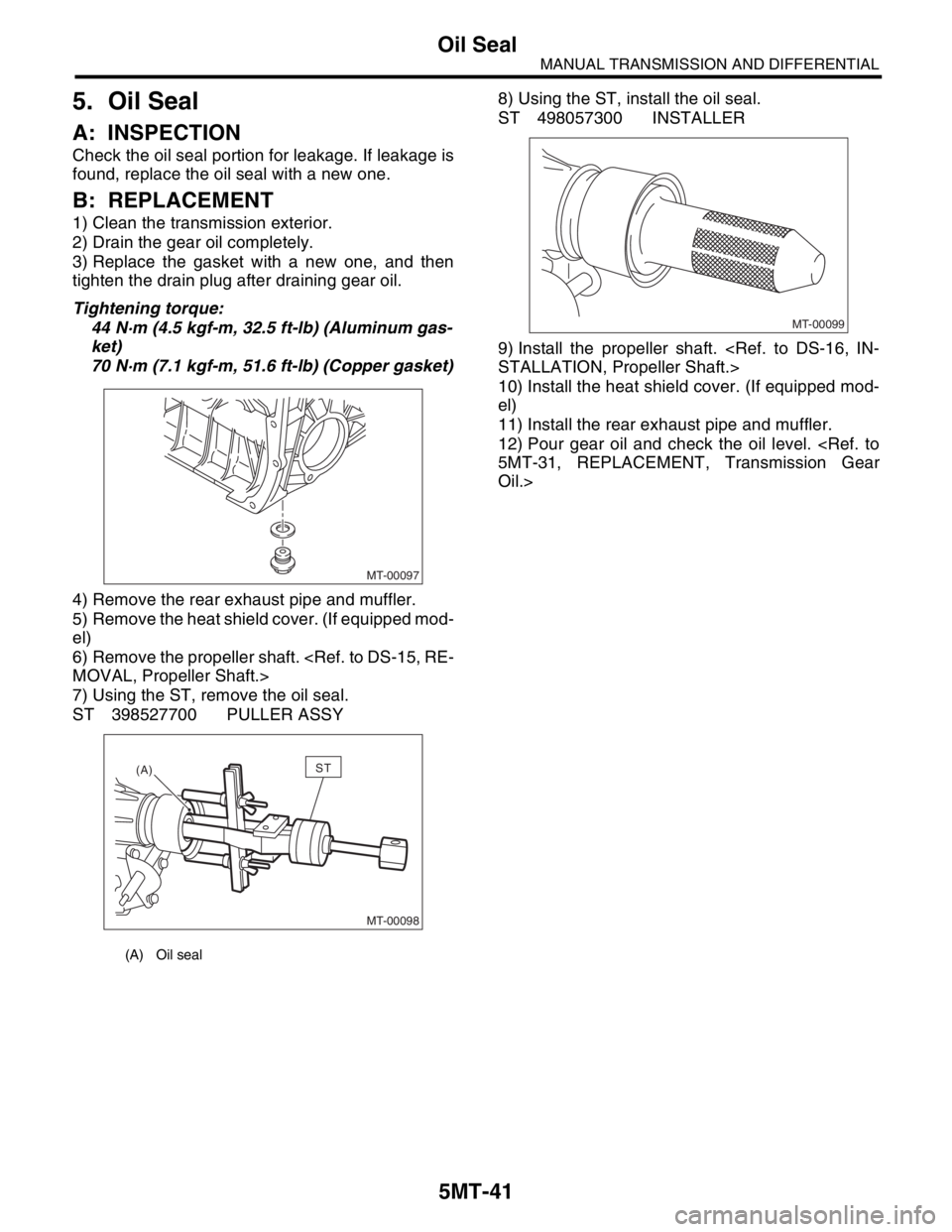
7) Using the ST, remove the oil seal.
ST 398527700 PULLER ASSY8) Using the ST, install the oil seal.
ST 498057300 INSTALLER
9) Install the propeller shaft.
10) Install the heat shield cover. (If equipped mod-
el)
11) Install the rear exhaust pipe and muffler.
12) Pour gear oil and check the oil level.
Oil.>
(A) Oil seal
MT-00097
MT-00098
(A)ST
MT-00099
Page 2754 of 2870
5MT-42
MANUAL TRANSMISSION AND DIFFERENTIAL
Differential Side Retainer Oil Seal
6. Differential Side Retainer Oil
Seal
A: INSPECTION
Check the differential side retainer oil seal for leak-
age of gear oil. If oil leaks, replace the oil seal.
B: REPLACEMENT
1) Lift-up the vehicle.
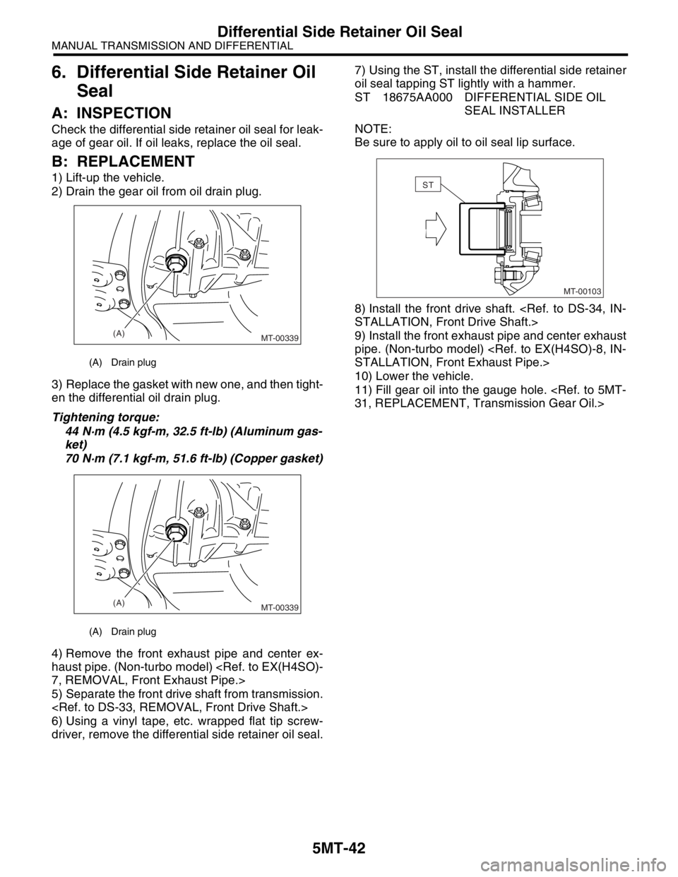
2) Drain the gear oil from oil drain plug.
3) Replace the gasket with new one, and then tight-
en the differential oil drain plug.
Tightening torque:
44 N·m (4.5 kgf-m, 32.5 ft-lb) (Aluminum gas-
ket)
70 N·m (7.1 kgf-m, 51.6 ft-lb) (Copper gasket)
4) Remove the front exhaust pipe and center ex-
haust pipe. (Non-turbo model)
5) Separate the front drive shaft from transmission.
6) Using a vinyl tape, etc. wrapped flat tip screw-
driver, remove the differential side retainer oil seal.7) Using the ST, install the differential side retainer
oil seal tapping ST lightly with a hammer.
ST 18675AA000 DIFFERENTIAL SIDE OIL
SEAL INSTALLER
NOTE:
Be sure to apply oil to oil seal lip surface.
8) Install the front drive shaft.
9) Install the front exhaust pipe and center exhaust
pipe. (Non-turbo model)
10) Lower the vehicle.
11) Fill gear oil into the gauge hole.
(A) Drain plug
(A) Drain plug
(A)
MT-00339
(A)
MT-00339
MT-00103
ST
Page 2764 of 2870
5MT-52
MANUAL TRANSMISSION AND DIFFERENTIAL
Transfer Case and Extension Case Assembly
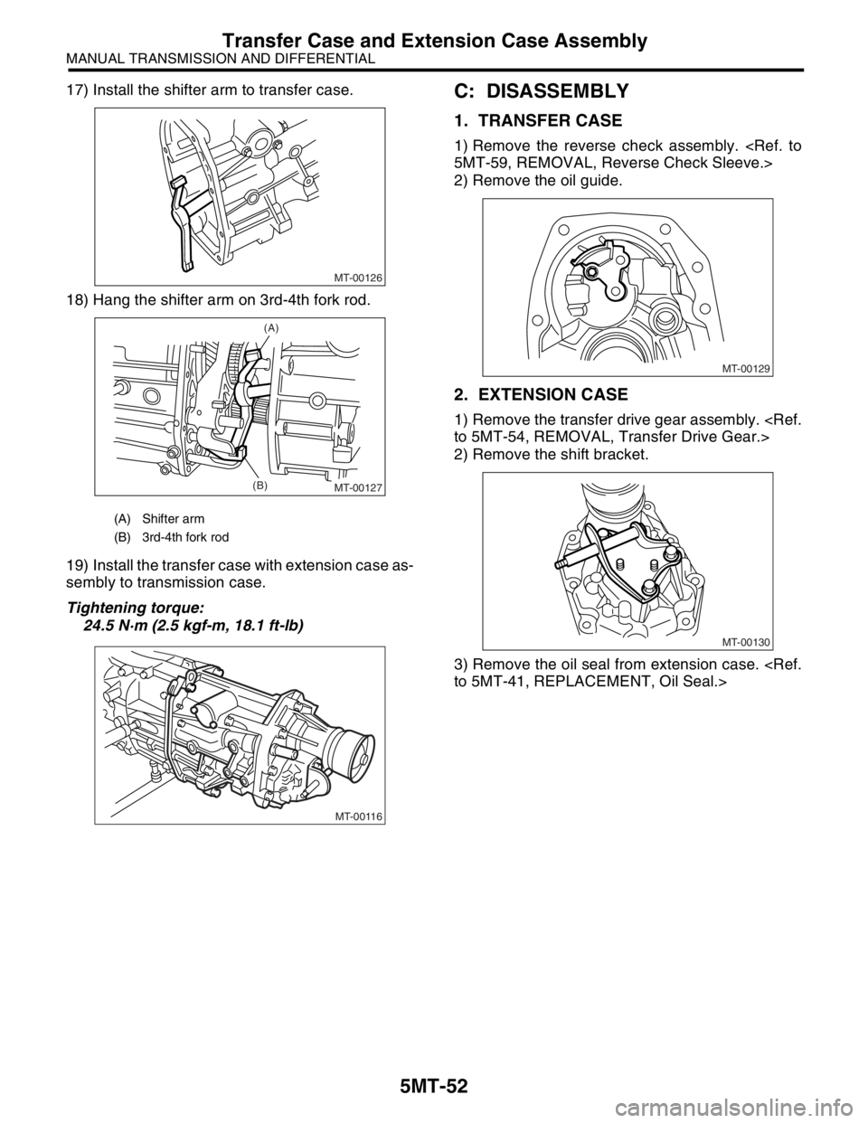
17) Install the shifter arm to transfer case.
18) Hang the shifter arm on 3rd-4th fork rod.
19) Install the transfer case with extension case as-
sembly to transmission case.
Tightening torque:
24.5 N·m (2.5 kgf-m, 18.1 ft-lb)C: DISASSEMBLY
1. TRANSFER CASE
1) Remove the reverse check assembly.
2) Remove the oil guide.
2. EXTENSION CASE
1) Remove the transfer drive gear assembly.
2) Remove the shift bracket.
3) Remove the oil seal from extension case.
(A) Shifter arm
(B) 3rd-4th fork rod
MT-00126
MT-00127
(A)
(B)
MT-00116
MT-00129
MT-00130