Page 2378 of 2870
4AT-65
AUTOMATIC TRANSMISSION
Control Valve Body
6) Fill liquid gasket to holes except for bolt holes
(three) of transmission case.
Liquid gasket:
THREE BOND 1217B (Part No. K0877YA020)
7) Install the oil pan with equally tighten the bolts.
Tightening torque:
5 N
⋅m (0.5 kgf-m, 3.6 ft-lb)
8) Pour ATF from the ATF charge pipe.
Recommended fluid:
DEXRON III type automatic transmission flu-
id
Capacity:
Pour fluid as same amount as drained fluid
from drain plug hole.
9) Bleed the air of control valve.
Air Bleeding of Control Valve.>
10) Check the ATF level.
matic Transmission Fluid.>
11) Execute the learning control promotion.
to 4AT(H4DOTC)-17, FACILITATION OF LEARN-
ING CONTROL, OPERATION, Subaru Select
Monitor.>
C: DISASSEMBLY
Non-turbo model only
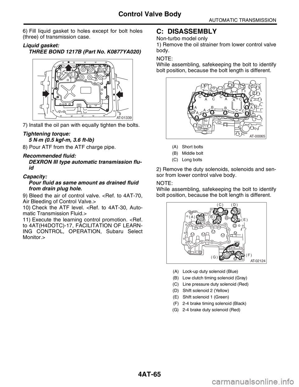
1) Remove the oil strainer from lower control valve
body.
NOTE:
While assembling, safekeeping the bolt to identify
bolt position, because the bolt length is different.
2) Remove the duty solenoids, solenoids and sen-
sor from lower control valve body.
NOTE:
While assembling, safekeeping the bolt to identify
bolt position, because the bolt length is different.
AT-01339
(A) Short bolts
(B) Middle bolt
(C) Long bolts
(A) Lock-up duty solenoid (Blue)
(B) Low clutch timing solenoid (Gray)
(C) Line pressure duty solenoid (Red)
(D) Shift solenoid 2 (Yellow)
(E) Shift solenoid 1 (Green)
(F) 2-4 brake timing solenoid (Black)
(G) 2-4 brake duty solenoid (Red)
AT-00065
A
ABAA
AC
ACC
AB
AC
CC
AT-02124
(E)
(F)(G)
(D)(C)
(B)(A)
Page 2385 of 2870
4AT-72
AUTOMATIC TRANSMISSION
Shift Solenoids, Duty Solenoids and ATF Temperature Sensor
2) Tighten the bolt and nut.
Tightening torque:
8 N
⋅m (0.8 kgf-m, 5.8 ft-lb)
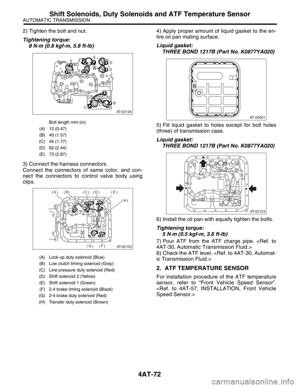
3) Connect the harness connectors.
Connect the connectors of same color, and con-
nect the connectors to control valve body using
clips.4) Apply proper amount of liquid gasket to the en-
tire oil pan mating surface.
Liquid gasket:
THREE BOND 1217B (Part No. K0877YA020)
5) Fill liquid gasket to holes except for bolt holes
(three) of transmission case.
Liquid gasket:
THREE BOND 1217B (Part No. K0877YA020)
6) Install the oil pan with equally tighten the bolts.
Tightening torque:
5 N
⋅m (0.5 kgf-m, 3.6 ft-lb)
7) Pour ATF from the ATF charge pipe.
4AT-30, Automatic Transmission Fluid.>
8) Check the ATF level.
ic Transmission Fluid.>
2. ATF TEMPERATURE SENSOR
For installation procedure of the ATF temperature
sensor, refer to “Front Vehicle Speed Sensor”.
Speed Sensor.>
Bolt length mm (in)
(A) 12 (0.47)
(B) 40 (1.57)
(C) 45 (1.77)
(D) 62 (2.44)
(E) 73 (2.87)
(A) Lock-up duty solenoid (Blue)
(B) Low clutch timing solenoid (Gray)
(C) Line pressure duty solenoid (Red)
(D) Shift solenoid 2 (Yellow)
(E) Shift solenoid 1 (Green)
(F) 2-4 brake timing solenoid (Black)
(G) 2-4 brake duty solenoid (Red)
(H) Transfer duty solenoid (Brown)
AT-02126
E
AD
EE
D
D
B
CC
AT-02122
(A) (B) (C) (D) (E)
(H)
(F)
(G)
AT-00051
AT-02123
Page 2389 of 2870
4AT-76
AUTOMATIC TRANSMISSION
ATF Filter
21.ATF Filter
A: REMOVAL
NOTE:
The ATF filter is maintenance free.
1) Lift-up the vehicle.
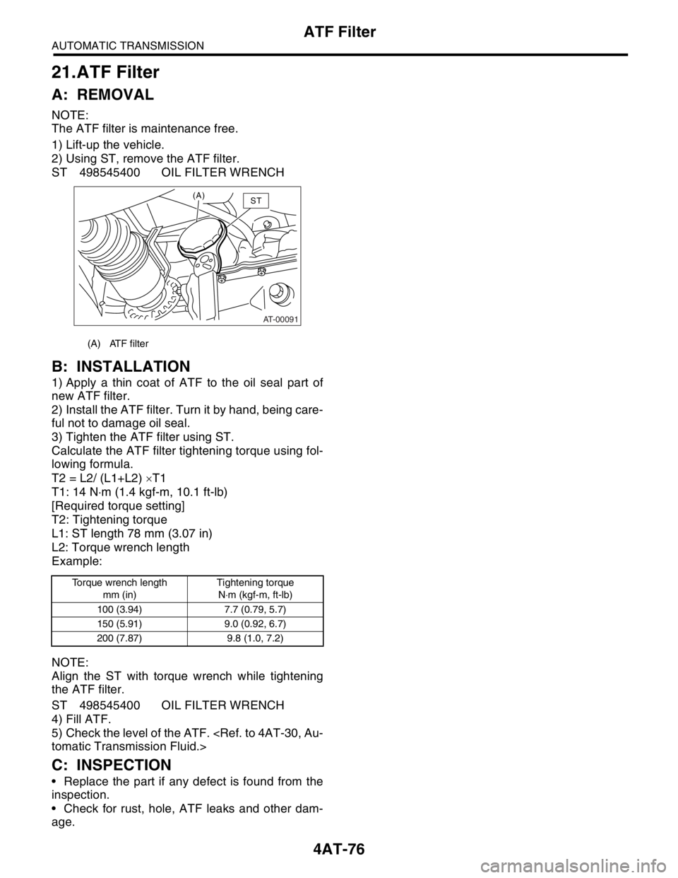
2) Using ST, remove the ATF filter.
ST 498545400 OIL FILTER WRENCH
B: INSTALLATION
1) Apply a thin coat of ATF to the oil seal part of
new ATF filter.
2) Install the ATF filter. Turn it by hand, being care-
ful not to damage oil seal.
3) Tighten the ATF filter using ST.
Calculate the ATF filter tightening torque using fol-
lowing formula.
T2 = L2/ (L1+L2) ×T1
T1: 14 N⋅m (1.4 kgf-m, 10.1 ft-lb)
[Required torque setting]
T2: Tightening torque
L1: ST length 78 mm (3.07 in)
L2: Torque wrench length
Example:
NOTE:
Align the ST with torque wrench while tightening
the ATF filter.
ST 498545400 OIL FILTER WRENCH
4) Fill ATF.
5) Check the level of the ATF.
tomatic Transmission Fluid.>
C: INSPECTION
Replace the part if any defect is found from the
inspection.
Check for rust, hole, ATF leaks and other dam-
age.
(A) ATF filter
Torque wrench length
mm (in)Tightening torque
N⋅m (kgf-m, ft-lb)
100 (3.94) 7.7 (0.79, 5.7)
150 (5.91) 9.0 (0.92, 6.7)
200 (7.87) 9.8 (1.0, 7.2)
AT-00091
(A)ST
Page 2402 of 2870
4AT-89
AUTOMATIC TRANSMISSION
Torque Converter Clutch Assembly
28.Torque Converter Clutch As-
sembly
A: REMOVAL
1) Remove the transmission assembly from vehi-
cle.
mission Assembly.>
2) Pull out the torque converter clutch assembly
and oil pump shaft horizontally.
CAUTION:
Be sure not to scratch the inside of bush in oil
pump shaft.
3) Remove the input shaft.
NOTE:
When the torque converter clutch assembly is re-
moved, the input shaft is also removed.
4) Remove the clips from torque converter clutch
assembly.
B: INSTALLATION
1) Install the clip to torque converter clutch case.
2) Install the oil pump shaft to torque converter
clutch assembly, and then make sure that the clip is
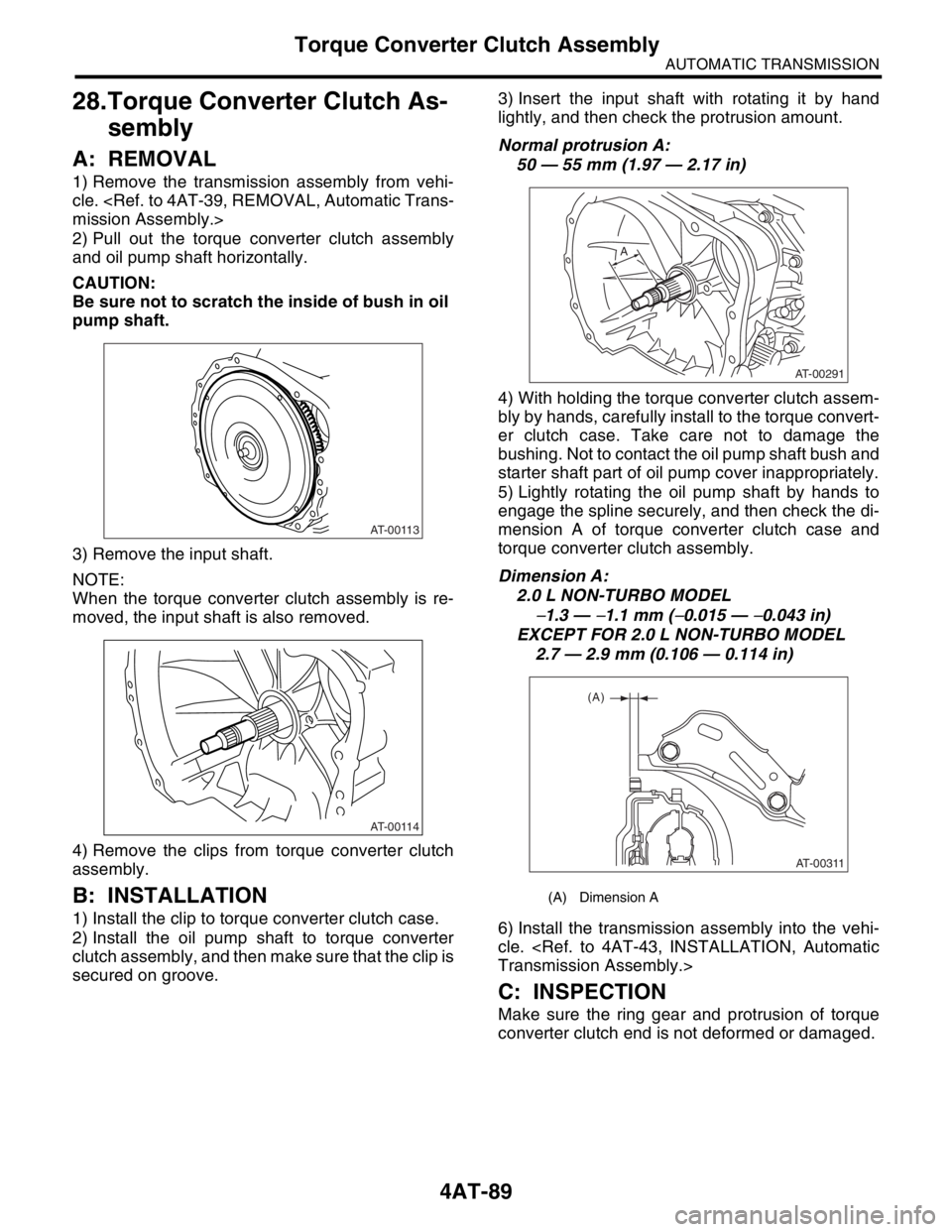
secured on groove.3) Insert the input shaft with rotating it by hand
lightly, and then check the protrusion amount.
Normal protrusion A:
50 — 55 mm (1.97 — 2.17 in)
4) With holding the torque converter clutch assem-
bly by hands, carefully install to the torque convert-
er clutch case. Take care not to damage the
bushing. Not to contact the oil pump shaft bush and
starter shaft part of oil pump cover inappropriately.
5) Lightly rotating the oil pump shaft by hands to
engage the spline securely, and then check the di-
mension A of torque converter clutch case and
torque converter clutch assembly.
Dimension A:
2.0 L NON-TURBO MODEL
−1.3 — −1.1 mm (−0.015 — −0.043 in)
EXCEPT FOR 2.0 L NON-TURBO MODEL
2.7 — 2.9 mm (0.106 — 0.114 in)
6) Install the transmission assembly into the vehi-
cle.
Transmission Assembly.>
C: INSPECTION
Make sure the ring gear and protrusion of torque
converter clutch end is not deformed or damaged.
AT-00113
AT-00114
(A) Dimension A
AT-00291
A
AT-00311
(A)
Page 2417 of 2870
4AT-103
AUTOMATIC TRANSMISSION
Torque Converter Clutch Case
B: INSTALLATION
1) Check the appearance of each component and
clean them.
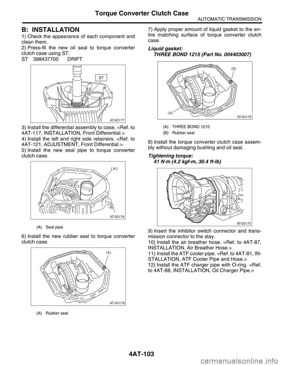
2) Press-fit the new oil seal to torque converter
clutch case using ST.
ST 398437700 DRIFT
3) Install the differential assembly to case.
4AT-117, INSTALLATION, Front Differential.>
4) Install the left and right side retainers.
4AT-121, ADJUSTMENT, Front Differential.>
5) Install the new seal pipe to torque converter
clutch case.
6) Install the new rubber seal to torque converter
clutch case.7) Apply proper amount of liquid gasket to the en-
tire matching surface of torque converter clutch
case.
Liquid gasket:
THREE BOND 1215 (Part No. 004403007)
8) Install the torque converter clutch case assem-
bly without damaging bushing and oil seal.
Tightening torque:
41 N
⋅m (4.2 kgf-m, 30.4 ft-lb)
9) Insert the inhibitor switch connector and trans-
mission connector to the stay.
10) Install the air breather hose.
INSTALLATION, Air Breather Hose.>
11) Install the ATF cooler pipe.
STALLATION, ATF Cooler Pipe and Hose.>
12) Install the ATF charger pipe with O-ring.
to 4AT-88, INSTALLATION, Oil Charger Pipe.>
(A) Seal pipe
(A) Rubber seal
AT-00177
AT-00176
AT-00178
(A)
(A) THREE BOND 1215
(B) Rubber seal
(B)
(A)
AT-00179
AT-00175
Page 2419 of 2870
4AT-105
AUTOMATIC TRANSMISSION
Oil Pump Housing
35.Oil Pump Housing
A: REMOVAL
1) Remove the transmission assembly from vehi-
cle.
mission Assembly.>
2) Pull out the torque converter clutch assembly.
Clutch Assembly.>
3) Remove the input shaft.
4) Lift-up the lever on rear side of transmission har-
ness connector, and then disconnect it from the
stay.
5) Disconnect the inhibitor switch connector from
the stay.
6) Remove the ATF charger pipe.
REMOVAL, Oil Charger Pipe.>
7) Remove the ATF cooler inlet and outlet pipes.
Hose.>
8) Separate the torque converter clutch case and
transmission case part.
MOVAL, Torque Converter Clutch Case.>
9) Separate the transmission case and extension
case part.
Case.>
10) Remove the reduction drive gear.
99, REMOVAL, Reduction Drive Gear.>
11) Remove the reduction driven gear.
4AT-97, REMOVAL, Reduction Driven Gear.>
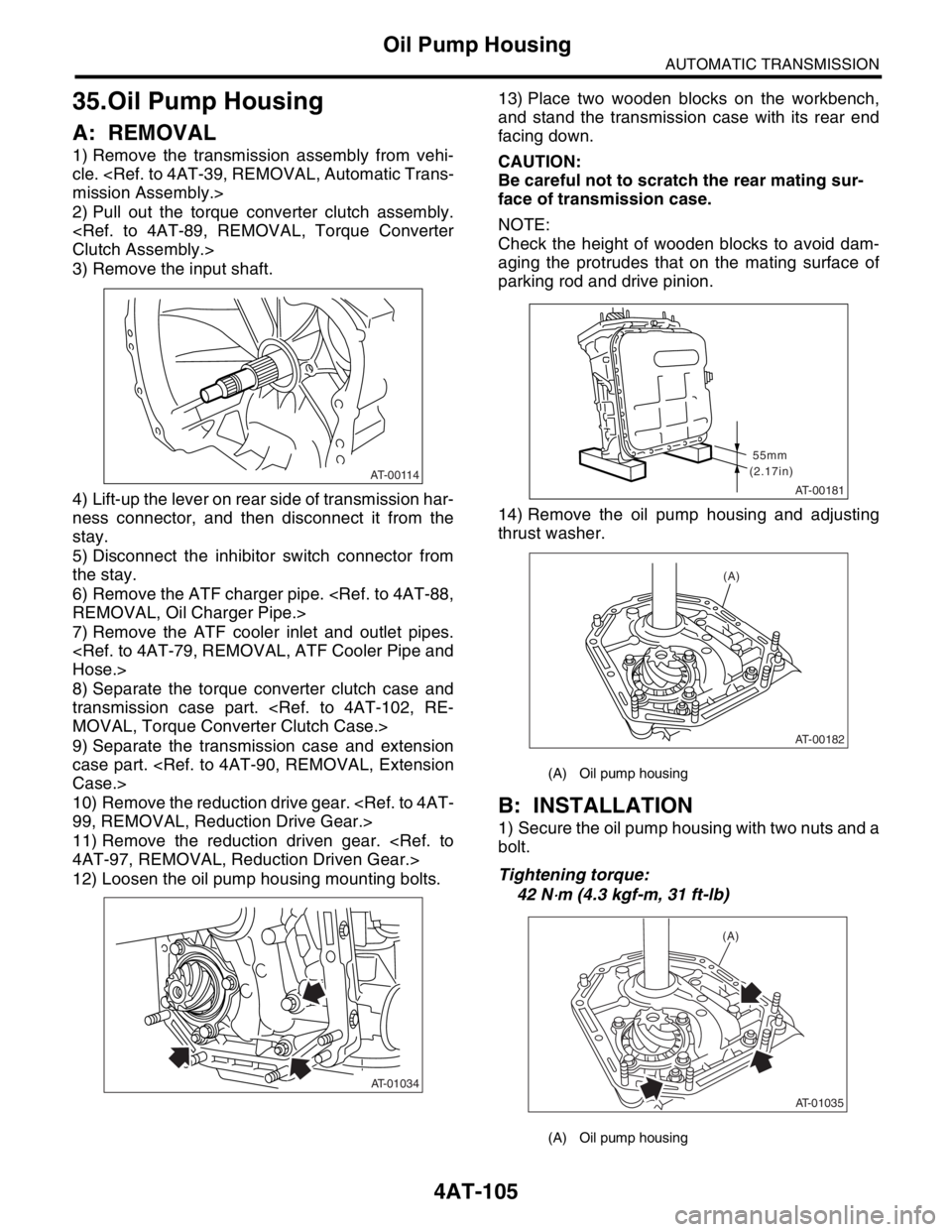
12) Loosen the oil pump housing mounting bolts.13) Place two wooden blocks on the workbench,
and stand the transmission case with its rear end
facing down.
CAUTION:
Be careful not to scratch the rear mating sur-
face of transmission case.
NOTE:
Check the height of wooden blocks to avoid dam-
aging the protrudes that on the mating surface of
parking rod and drive pinion.
14) Remove the oil pump housing and adjusting
thrust washer.
B: INSTALLATION
1) Secure the oil pump housing with two nuts and a
bolt.
Tightening torque:
42 N
⋅m (4.3 kgf-m, 31 ft-lb)
AT-00114
AT-01034
(A) Oil pump housing
(A) Oil pump housing
AT-00181
(2.17in)55mm
AT-00182
(A)
AT-01035
(A)
Page 2420 of 2870
4AT-106
AUTOMATIC TRANSMISSION
Oil Pump Housing
2) Install the torque converter clutch case to trans-
mission case.
Torque Converter Clutch Assembly.>
3) Install the reduction driven gear.
97, INSTALLATION, Reduction Driven Gear.>
4) Install the reduction drive gear.
INSTALLATION, Reduction Drive Gear.>
5) Align the transmission case and extension case.
Case.>
6) Insert the inhibitor switch and transmission con-
nector to the stay.
7) Install the ATF cooler pipe.
STALLATION, ATF Cooler Pipe and Hose.>
8) Install the ATF charger pipe with O-ring.
4AT-88, INSTALLATION, Oil Charger Pipe.>
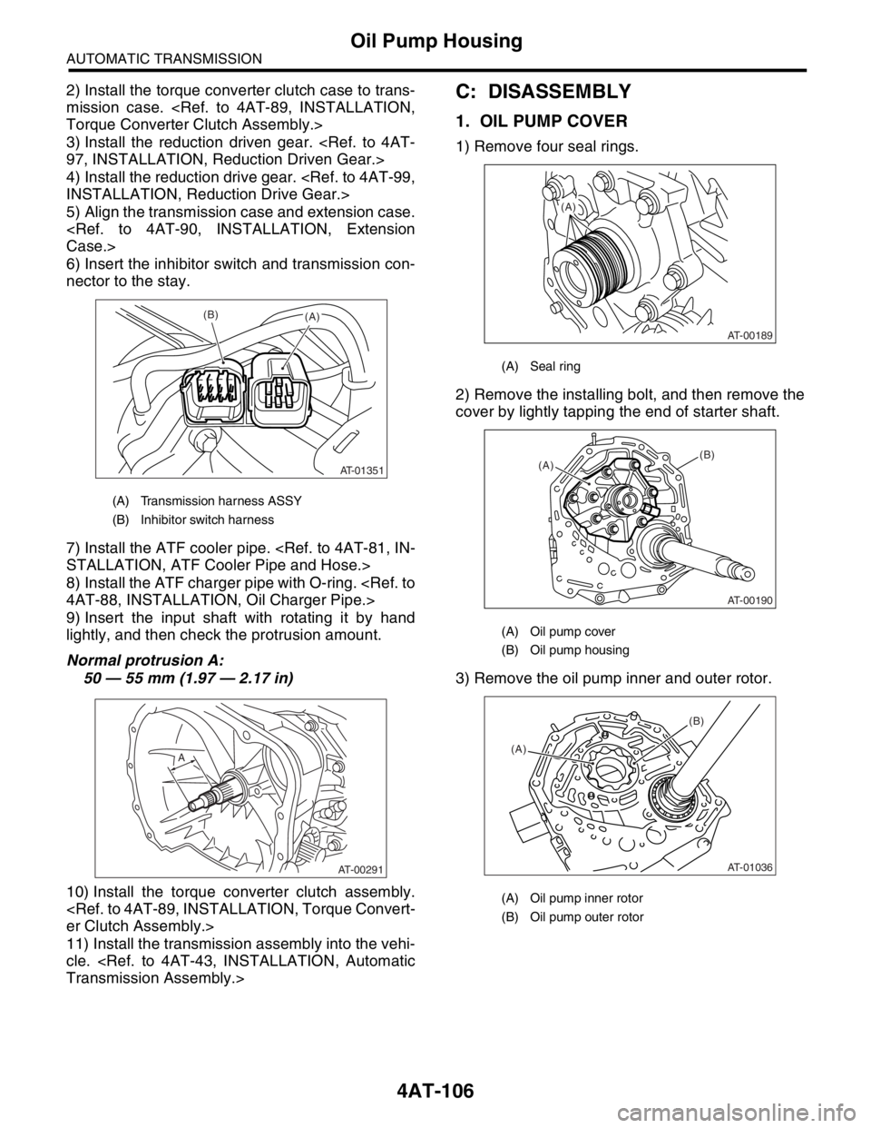
9) Insert the input shaft with rotating it by hand
lightly, and then check the protrusion amount.
Normal protrusion A:
50 — 55 mm (1.97 — 2.17 in)
10) Install the torque converter clutch assembly.
er Clutch Assembly.>
11) Install the transmission assembly into the vehi-
cle.
Transmission Assembly.>C: DISASSEMBLY
1. OIL PUMP COVER
1) Remove four seal rings.
2) Remove the installing bolt, and then remove the
cover by lightly tapping the end of starter shaft.
3) Remove the oil pump inner and outer rotor.
(A) Transmission harness ASSY
(B) Inhibitor switch harness
AT-01351
(B)(A)
AT-00291
A
(A) Seal ring
(A) Oil pump cover
(B) Oil pump housing
(A) Oil pump inner rotor
(B) Oil pump outer rotor
AT-00189
(A)
AT-00190
(A)(B)
AT-01036
(A)(B)
Page 2421 of 2870
4AT-107
AUTOMATIC TRANSMISSION
Oil Pump Housing
2. OIL SEAL RETAINER
1) Remove the oil seal retainer.
2) Remove the O-ring.
3) Remove the oil seal from oil seal retainer.
D: ASSEMBLY
1. OIL PUMP COVER
1) Install the oil pump rotor assembly to oil pump
housing.
2) Align both pivots with the pivot holes of cover,
and then install the oil pump cover being careful not
to apply excessive force to the pivots.
Tightening torque:
25 N
⋅m (2.5 kgf-m, 18.1 ft-lb)
3) After assembling, turn the oil pump shaft to
check the smooth rotation of rotor.
(A) Oil seal retainer
(B) Drive pinion shaft
(A) O-ring
(A) Oil seal
(B) Oil seal retainer
AT-00183
(A)(B)
AT-00186
(A)
AT-00185
(A)
(B)
(A) Oil pump inner rotor
(B) Oil pump outer rotor
(A) Oil pump cover
(B) Oil pump housing
AT-01036
(A)(B)
AT-00190
(A)(B)